Introduction
The fast kinetics of the oxygen reduction reaction (ORR) in alkaline fuel cells (AFCs) allows the use of non-noble metal electro catalysts. Therefore, it is useful to evaluate the electrochemical operations of the AFCs in specific areas of the relationship between cell potential and current density. The endeavor to develop non-noble catalysts for the ORR in combination with ion conductive polymer electrolyte for mobile and autonomous uses has been recognized as the future for alternative power generation technique.[ Reference Jacobson, Colella and Golden 1 , Reference Steele and Heinzel 2 ] Various types have been developed,[ Reference Jacobson, Colella and Golden 1 , Reference Steele and Heinzel 2 ] such as AFC, phosphoric acid fuel cell (PAFC), molten carbonate fuel cell (MCFC), solid oxide fuel cell (SOFC), and polymer electrolyte fuel cell (PEFC). According to that PEFC has been the most developed one in the past two decades,[ Reference Borup, Meyers, Pivovar, Kim, Mukundan, Garland, Myers, Wilson, Garzon, Wood, Zelenay, More, Stroh, Zawodzinski, Boncella, McGrath, Inaba, Miyatake, Hori, Ota, Ogumi, Miyata, Nishikata, Siroma, Uchimoto, Yasuda, Kimijima and Iwashita 3 ] featuring rapid start-up and high-power density particularly suitable for vehicle applications.[ Reference Jacobson, Colella and Golden 1 – Reference Borup, Meyers, Pivovar, Kim, Mukundan, Garland, Myers, Wilson, Garzon, Wood, Zelenay, More, Stroh, Zawodzinski, Boncella, McGrath, Inaba, Miyatake, Hori, Ota, Ogumi, Miyata, Nishikata, Siroma, Uchimoto, Yasuda, Kimijima and Iwashita 3 ] The strong acidic nature of the proton conductive membranes such as Nafion requires the employment of expensive noble metals such as Pt in order to ensure stable behavior against corrosion. Although a lot of effort was expended[ Reference Bashyam and Zelenay 4 , Reference Suo, Zhuang and Lu 5 ] on finding non-noble metal catalysts there is still no material of choice which ensures a Pt-like performance. Thus, to get rid of noble metal catalyst, alkaline electrolyte has to be taken into account.
The working principle of an alkaline polymer electrolyte membrane fuel cell (AEMFC) differs from that of Nafion based a PEFC.[ Reference Sahu, Pitchumani, Sridhar and Shukla 6 – Reference Fan 9 ] The ORR takes place at the cathode where O2 is being reduced in the presence of water to OH− which then passes through the OH− conductive polymer to the anode and reacts with H2 to produce water.
By using polymer electrolytes the leakage of the electrolyte can be overcome by retaining the separation of the anode and the cathode with a thin film of a few tens of microns in thickness. Another important issue which can be overcome is the suffering from the carbonation when the air is used as an oxidant and the waterproof character of the gas-diffusion electrode cannot be managed due to clogging the pores by the formation of K2CO3. A solution for this issue is to use an alkaline polymer electrolyte (APE) where the cation, predominantly a quaternary ammonium is attached at the polymer side chains without any dissolution process of the cation which suppresses the formations of K2CO3. Unlike devices relying on a proton exchange membrane (PEM), it is possible to use an fuel cell with an alkaline anion exchange membrane (AAEM) to separate the anode from the cathode. The high pH allows the usage of a precious-metal-free ORR catalyst. There are three major challenges in the development of a catalyst for the non-noble electrode. First of all the catalyst has to show good catalytic activity. Additionally, it has to be stable against oxidation, dissolution or other degradation. Finally, the structure of the catalyst is of paramount importance as it has to provide a high amount of triple phase boundary (TPB) at a high electrical conductivity. This can be achieved by using a chromium–nickel (Cr–Ni) catalyst supported by carbon fibers fabricated by electrospinning which is done in this work. We show that according to the density functional theory (DFT) calculations the impact of different chromium fractions on the ORR is largely different. The catalytic activity, as estimated by the calculated critical electrode potential, is increased for all considered Cr modified structures compared with the Cr-free structures at the same coverage.
In the past, a lot of effort has been spent on the evaluation of a AEMFC[ Reference Asazawa, Yamada, Tanaka, Oka, Taniguchi and Kobayashi 10 – Reference Varcoe and Slade 12 ] but the progress has been hampered by operational issues like leakage and stability problems. A suitable APE should be Nafion like with a high conductivity; mechanically stable and soluble in alcohol without any cross-networking in order to impregnate the desired counter ion easily with the polymer electrolyte. Here the membrane was wetted in aqueous solutions of KOH (pH = 14) to ensure a good OH conductivity.[ Reference Agel, Bouet and Fauvarque 13 – Reference Matsuoka, Iriyama, Abe, Matsuoka and Ogumi 15 ] Here we focus on an approach[ Reference Yang, Bhattacharjya, Inamdar, Park and Yu 16 – Reference Yang, Fellinger and Antonietti 18 ] to overcome the dependency on noble metals for the ORR at the cathode side as well as the employment of an AEMFC. With the DFT calculations, we discover a tendency of suitable catalyst material for good ORR. Combining the modeling and the experimental approaches enabled the developments in the present work.
Experimental
Computational methods
The method to calculate the free energy taking into account the electrode potential has been used previously in a number of studies.[ Reference Keith, Jerkiewicz and Jacob 19 , Reference Nørskov, Rossmeisl, Logadottir, Lindqvist, Kitchin, Bligaard and Jónsson 20 ] Here we assume the dissociative ORR pathway with the following reaction steps:
 $$\displaystyle{{\rm 1} \over 2}O_2 + \ast \to {\rm O}^{\ast}$$
 $${\rm O}^{\ast} +H^{+} + e^{-} \to {\rm OH}^{\ast}$$
 $${\rm OH}^{\ast} + H^{+} + e^{-} \to H_2O + \ast$$
The asterisk (*) denotes an active side or an adsorbed specie. The simulation workflow and all relevant parameters are described in detail in a previous work and have been used in this work without changes.[ Reference Kondov, Faubert and Müller 21 ] From the thus obtained energies (ΔE), vibrational entropies (ΔS), and zero-point energies (ΔZPE) the free energies of the species in the reactions (1), (2) and (3) were calculated whereby the proton-electron pair (H + + e −) is substituted by 1/2 H2 gas:
 $$\Delta G = \Delta G_0 - neU_{\rm RHE} = \Delta E + \Delta {\rm ZPE} - T\Delta S - neU_{\rm RHE}$$
The effective reversible potential was calculated using the formula[ Reference Anderson, Jinnouchi and Uddin 22 ]
 $$U_{\rm eff} = U_0 + \displaystyle{1 \over n}\Delta G_0^{(1)}$$
where U
0 = 1.229 V is the standard reversible potential for the ORR reaction and
 $\Delta G_0^{(1)} $
is the standard Gibbs free energy of the dissociative adsorption of O2. The critical potential U
max was found as the highest possible potential at which all ORR steps (1), (2), and (3) are spontaneous, i.e. with non-positive free energies.
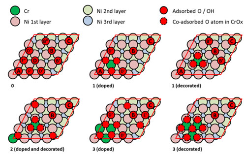
All electronic structure calculations were carried out using DFT as implemented in the Vienna ab initio simulation program, VASP[ Reference Kresse and Hafner 23 , Reference Blöchl 24 ] with the Perdew–Burke–Ernzerhof (PBE) density functional.[ Reference Perdew, Burke and Ernzerhof 25 ] Again, all methods and parameters from Ref. Reference Kondov, Faubert and Müller21 were used here without modification. The DFT calculations of different surface structures have been performed based on a 4 × 4 periodic slab describing the (111) surface of fcc Ni including five atomic layers. All adsorbate species and the atoms in the three top layers in the slab were relaxed and the two bottom layers were kept fixed. To investigate the influence of Cr, two types of modifications of the surface were considered: (1) nickel atoms in the top surface layer were replaced with Cr atoms which will be referred to as Cr doping, and (2) chromium atoms were placed on vacant fcc surface sites which will be referred to as Cr decoration. We have varied the adsorbate coverage on the surface from 4/16 up to 9/16 ML (monolayer) and considered the ORR taking place at one vacancy, i.e. the surface concentration of the active sites was considered 1/16. The structures considered are outlined in the supporting information (see Supporting Informations Fig. S3).
Catalyst synthesis
The solution contains 4.5 g of NiCl2·6H2O and 1.1 g of CrCl3, 6H2O which was dissolved in 200 mL distillated pure water. After that Carbon black and Cr–Ni was added. Here the amount of Carbon black was four times higher than Cr–Ni. Then 114 mL of 5 wt% NaBH4 solution was added drop-wise into the suspension at 10 °C followed by stirring for 30 min. By using distillated pure water and a vacuum pump the received catalyst power was washed until no Cl-could be detected anymore. In the next step, the powder was dried in vacuum for 4 h at 100 °C, and cooled down to room temperature. The resulting powder was added in a glazed ceramic boat and heated under an N2 atmosphere at 120 °C for 0.5 h and then at 350 °C for 0.5 h to drive the boron completely away from the catalyst. The resulting electrode reveals a thickness of 180 µm (SEM, Fig. S1) and a particle size of ca.185 nm (SEM/BSE, Fig. S1) with homogenous distribution of the Cr–Ni particles.
Cathode fabrication by electrospinning and carbonization
The fabrication of the cathode material contains two steps. The first step was an electrospinning process and the second step was a carbonization process. Here the catalyst particles were added into a carbon precursor polymer (Polyacrylonitrile, MW 150,000, Sigma-Aldrich, Germany) solution in N,N-dimethylacetamide (Carl Roth, Germany) and stirred at 70 °C overnight and subsequent sonication for 10 min in order to get a suspension. The ratio of the ingredients was 0.6 wt% catalyst particles, 8.1 wt% polyacrylonitrile, and 91.3 wt% N, N-dimethylacetamide. By using a modified Kato Tech Nanofiber Electrospinning Unit (see Supporting Informations Fig. S2) the suspension was eletrospun. The needle collector distance was 22.9 cm, needle collector voltage 19 kV, feed rate 0.864 mL/h and the collector rotation 9 m/min. The fibers were deposited on a non-stick fabric to ensure a complete, distortion-free peel-off. In a second step the polymer fiber mats containing the catalyst were carbonized (stabilization in the air at 230 °C, carbonization in N2 at 1100 °C) using a tube Furnace (Gero-Carbolite, Germany). The obtained carbon fiber fleece (V) are electrically conductive and are crafted with 15 up to 16 wt% catalyst particles.
Linear sweep voltammetry (LSV) [rotating disc electrode (RDE) assembly]
The electrochemical measurements were controlled by the potentiostat Autolab PGSTAT126N and the software GPES (general purpose electrochemical system). The electrochemical characterization of the materials was carried out by cyclic voltammetry (CV), LSV. Here a three-electrode setup with a platinum sheet as a counter electrode and Ag/AgCl/3 M KCl as a reference electrode (double junction; Metrohm 6.0733.100) was used.
Then the Cr–Ni electrode was grinded and wetted in isopropanol in order to cover the glassy carbon electrode of 3 mm in diameter and bedded in a cylindrical Teflon mold which was used as working electrode. The preparing process of the working electrode contains a pre-polishing step with aluminum oxide powder (grain size 0.3 µm) followed by a washing step with ethanol. Thus 5 mg of the catalyst powder was dispersed in 5 ml isopropanol and sonicated for 30 min in order to compose a homogeneous ink. Afterwards, 20 µL of the suspension ink were placed onto the glassy carbon electrode and dried in air for at least 24 h. The electrochemical measurements were carried out in alkaline 1 M aqueous potassium hydroxide (KOH) solution. RDE measurements were performed by EDI 101 from Radiometer at different rotation speeds from 400 rpm to 2025 rpm in air-saturated 1 M KOH solution. The Koutecky–Levich equation was applied to determine the number of the transferred electrons[ Reference Bard and Faulkner 26 ]
 $$\displaystyle{1 \over i} = \displaystyle{1 \over {i_k}} + \displaystyle{1 \over {i_l}}$$
 $$i_l = 0.2 \times n \times F \times D_0^{2/3} \times \nu ^{-1/6} \times C_0 \times w^{1/2}$$
Thereby i, the measured current density, is composed of i k , the kinetic-limiting current density and i l , the diffusion-limiting current density. Thus, a clear linear relationship between the diffusion-limiting current density and the inverse of the square root of w, the rotation speed, is derived from the Koutecky–Levich equation enabling the determination of n, the number of transferred electrons. Further parameters needed for the analysis are F, the Faraday constant (96,485 C/mol); D 0, the diffusion coefficient of oxygen (1.9 × 10⁻⁵ cm2/s); C 0, the bulk concentration of oxygen (2.5 × 10⁻⁷ mol/cm3, air-saturated solution); and ν, the kinetic viscosity (0.01 cm2/s).
Membrane preparation
The used ionomer was provided in different forms from which the most suitable one was built into the fuel cell. We choose as a polymer foil with Br- counter ion and the other one was provided as a foil-like precursor which was soluble in alcohol and N-methyl-2-pyrrolidone (NMP). The foil with the Br-counter ion was inserted in 1 M KOH solution with pH = 14 for 3 days by changing the KOH several times to ensure a good OH-conductive by replacing the Br-counter ion with a OH-ion. The polyaromate-based FAA-3 ionomer with quaternary ammonium functional groups has an ion exchange capacity (IEC)/chloride form of 1.6–2.0 mmol/g, a moisture content <10%, and inherent viscosity of 1.0–1.3 dL/g. Thermal gravimetric analysis measurements reveal that the ionomer is thermally stable up to 120 °C and, therefore, can be used safely at <100 °C. This membrane reveal also Nafion-like hydrophilic backbone penetrated by nanosized hydrophobic side-chain domains and provides therefore high ionic conductivity (about 40 mS/cm), good mechanically strength [1000–1800 MPa in Young's modulus at 23 °C/50% relative humidity (RH)] and an inherent viscosity of 1.0–1.3 dL/g which meets the requirements for AFC applications.
Fuel cell assembly
In this prototype a 5 cm2 fuel cell was constructed with Cr–Ni particles on carbon fiber supported as cathode catalyst at a loading of 5 mg/cm2, and 1.7 mg/cm2 Pt-C (20% Pt/C Platinum on carbon Elyst Pt 20, Umicore from Gaskatel) as anode catalyst layer combined with a OH-conductive APE from Fumatech. The fuel cell was operated with H2/O2 as reaction gases with flow rates of 0.5 L/min, 30 °C cell temperature, 100% RH and 300 kPa absolute pressure. Polarization data were recorded at 1 min/point. CV was recorded at a scan speed of 25 mV/s.
Results and discussions
Cr–Ni electrode supported by carbon fibers
Based on the theoretical investigations we fabricate a non-noble catalyst in combination with a polymer electrolyte a suitable membrane electrode unit for the employment in a fuel cell.
Calculated activity descriptors
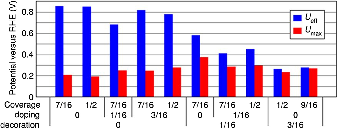
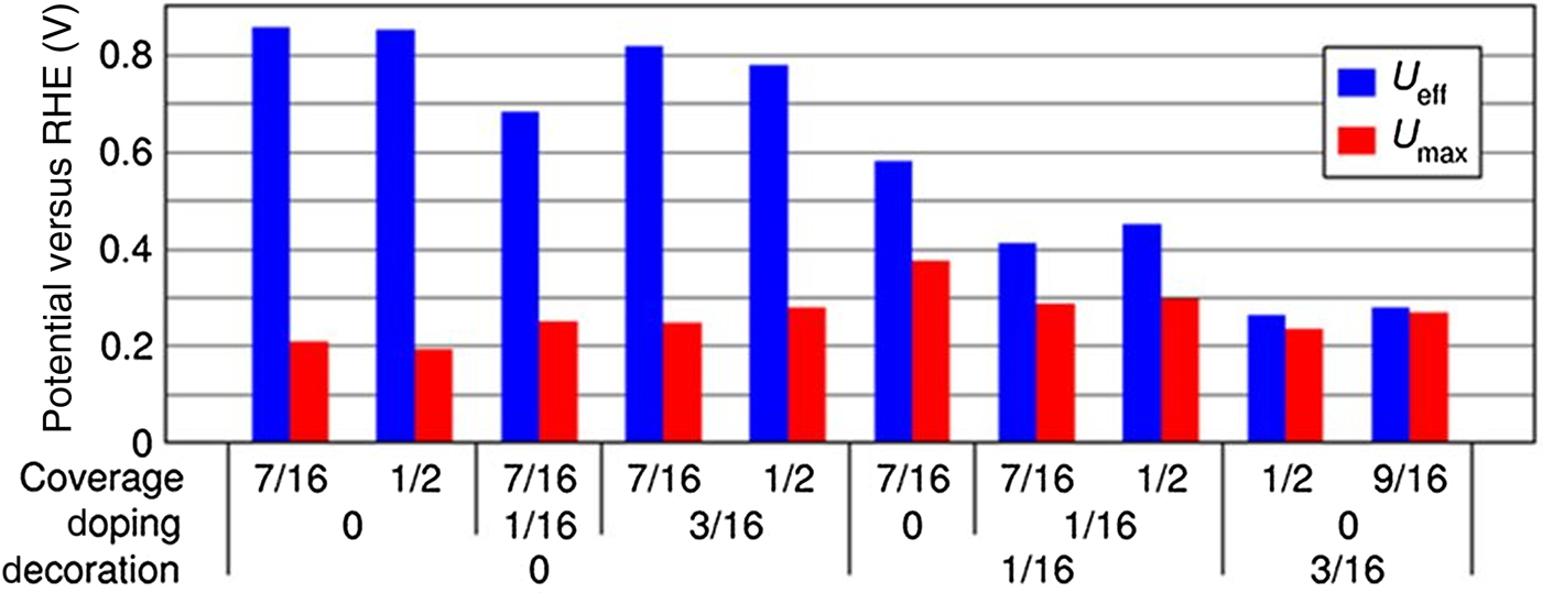
In order to better understand the increased activity of the Cr-modified catalyst and to suggest further catalyst design steps a simple model based on the electronic structure calculations was used to compute the so-called effective reversible potentials and the critical potentials for the various surface structures (see the “methods” section). The effective reversible potential U eff is a thermodynamic upper bound of the measured onset potential accounting for the loss due to free energy dissipation of ORR steps with no charge transfer. The critical potential U max is defined as the maximum potential for which all ORR steps are spontaneous and is always lower than U eff. These calculated potentials are depicted in Fig. 1 for the different surface structures. In Table I we provide statistics based on all calculations including those not displayed in Fig. 1. We have chosen relatively high surface coverages of adsorbates, 7/16, 8/16, and 9/16 ML. The computed effective reversible potentials for the Cr-free surface are above 0.8 V, while the U eff for the Cr-modified surfaces are all lower. The highest U eff found is 0.8 V for 3/16 Cr-doped surface at 7/16 ML coverage. The effective reversible potential U eff accounts for the free energy loss in all reactions at the electrode without electron transfer, reducing the power efficiency of the cell. In the case of ORR this is the dissociative O2 adsorption, reaction (1). Therefore, high U eff values are due to a weakening of the O–Ni bond and destabilization of adsorbed atomic oxygen. It is obvious that increasing the coverage on the pure Ni surface leads to sufficiently high U eff. Nevertheless, the ORR steps with electron transfer, i.e. reactions (2) and (3), cause additional lowering of the onset potentials.[ Reference Anderson, Jinnouchi and Uddin 22 ] In practice, the ORR will proceed only below the critical potential U max for which all three reactions (1), (2), and (3) are spontaneous. The highest calculated U max is 0.4 V on the 1/16 Cr-decorated surface at 7/16 ML coverage. The highest U max calculated on the Cr-free surface is 0.2 V at the same total adsorbate coverage. For the high-coverage and high U eff cases shown in Fig. 1, the Cr-modified structures exhibit higher U max than the Cr-free structures. The U max potential is closer to U eff for the Cr decorated structures than for the Cr-free and Cr-doped structures. This is related to relative stabilization of the hydroxyl which results in higher U max although U eff is lower. This can be illustrated with the case at 7/16 ML coverage in Fig. 1 where U eff and U max are 0.6 and 0.2 V for 1/16 doping and 0.6 and 0.4 V with 1/16 Cr decoration, respectively. The corresponding values for the Cr-free surface are 0.8 and 0.2 V, respectively. In the case of mixed doping and decoration a superposition of these two effects on U eff and U max is found. Apart from the activity enhancement discussed here, there is another effect due to Cr modification. In another work, we have shown that both Cr modifications, but particularly Cr decoration, significantly improves the stability against electrochemical dissolution and enables the employment of the Ni-based catalyst at high surface coverages and electrode potentials. Other factors not considered in this model are the occurrence probability of the different structures and their relative importance for the ORR, as well as the concentration of the ORR active sites. To tackle these aspects a kinetic Monte Carlo simulation can be performed including all relevant structures and corresponding rates.
Effective reversible potentials and critical potentials simulated for different fractions of doping and decorating Cr and for variate coverages. The potentials are calculated at T = 298.15 K and partial pressure of the H2 and O2 gases of 105 Pa (1 bar).
Minimum, maximum, and average values for U eff and U max versus RHE (V) for all 36 structures considered in the simulation.

U eff, effective reversible potential; U max , critical potential.
Cathode characterization
Motivated by the results of the DFT calculations we fabricated a fiber supported Cr–Ni catalyst electrode. We characterized the catalyst by SEM (see Supporting Informations Fig. S1) and XPS[ Reference Kondov, Faubert and Müller 21 ] in order to analyze the Cr 2p and Ni 2p spectra of the synthesized Cr–Ni particles and to determine the morphology of the developed material. Hereby the carbon fibers and the Cr–Ni particles can be observed very well. The active surface area found in the BET measurements is 288 m2/g. CV was performed to determine the electrochemical ORR activity of the plain catalyst material. To characterize the catalytic activity of the carbon-supported Cr–Ni electrode, the RDE technique was used to determine the onset potential and to elucidate the charge transfer processes of the ORR.
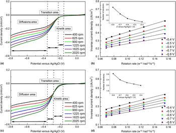
The CV curves are recorded in air-saturated 1 M KOH solution at a scan rate of 1 mV/s and displayed in a previous work. The onset potential represents a significant factor for the evaluation of the electrocatalytic activity of a catalyst.[ Reference Bard and Faulkner 26 ] Hence, to achieve better electrocatalytic ORR activity, a more positive onset potential is desired. Compared with the Ni electrode (−196 mV versus Ag/AgCl), the Cr-modified Ni electrode possesses positively shifted onset potential of −174 mV versus Ag/AgCl reference electrode indicating the improved electrocatalytic ORR activity as apparent in the inset. The electron transfer mechanism was further investigated in air-saturated alkaline media. Thus RDE measurements were performed at varying rotation speeds from 400 rpm up to 2025 rpm. The Koutecky–Levich equation was used to examine the number of the transferred electrons. The LSV curves of the Ni and Cr–Ni electrodes, shown in Figs. 2(a) and 2(c), demonstrate increasing current density with higher rotation speeds. The Koutecky–Levich (K–L) plots, applied to evaluate the electron transfer mechanism, are displayed in Figs. 2(b) and 2(d). The relationship between j−1 and w−1/2 is clearly linear from −0.4 to −0.8 V. The number of the transferred electrons (n) at certain potentials was determined from the slope of the K–L plots. For the Ni electrode, n was calculated to be 1.6 at −0.4 V, and 2.6 at −0.8 V.
(a) LSV curves for Ni-electrode (a) and Ni-Cr-electrode (c) recorded in alkaline KOH solution (1 M) at various rotation velocities with a scan rate of 5 mV/s. (b) Koutecky–Levich (K–L) plots for Ni-electrode (b) and Ni–Cr-electrode (d) at different cathodic potentials. The number of transferred electrons at the corresponding potentials is shown in the insets in (b) and (d). (c) LSV curves for Ni-electrode (a) and Ni–Cr-electrode (c) recorded in alkaline KOH solution (1 M) at various rotation velocities with a scan rate of 5 mV/s. (d) K-L plots for Ni-electrode (b) and Ni–Cr-electrode (d) at different cathodic potentials. The number of transferred electrons at the corresponding potentials is shown in the insets in (b) and (d).

In comparison, higher n was calculated for the Cr–Ni electrode, i.e. 2 at −0.4 V and 2.8 at −0.8 V. Although the ORR in both samples is mainly dominated by the two-electron pathway, the results demonstrate an improved electron transfer for the electrode with Cr. Besides, with regard to well-distributed oxygen in electrolyte and diffusion matters based on the high porosity of the assembly, the higher current densities of Cr–Ni electrode confirm the enhanced electrocatalytic activity of the material towards ORR.
Cell polarization curve and power density
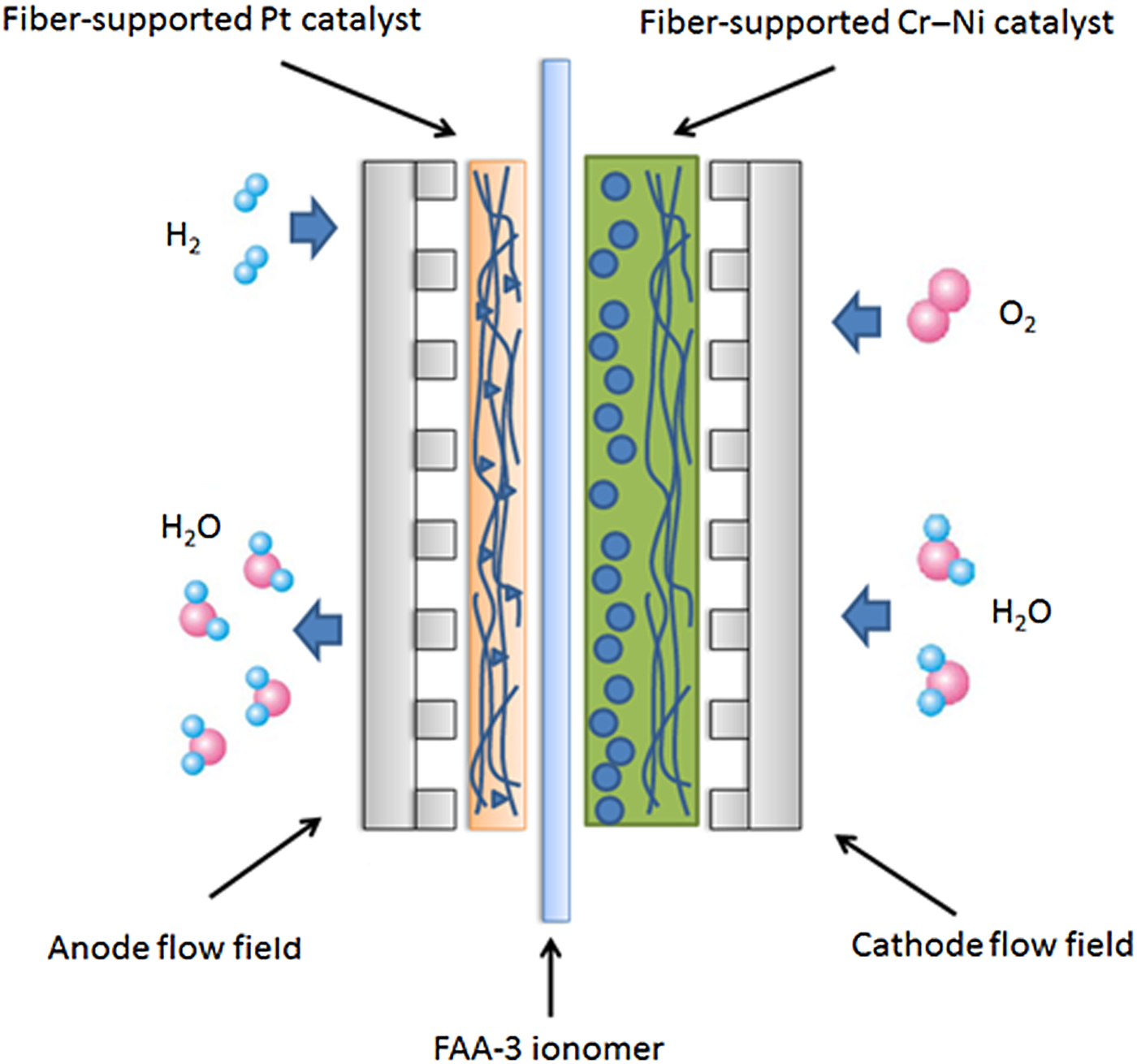
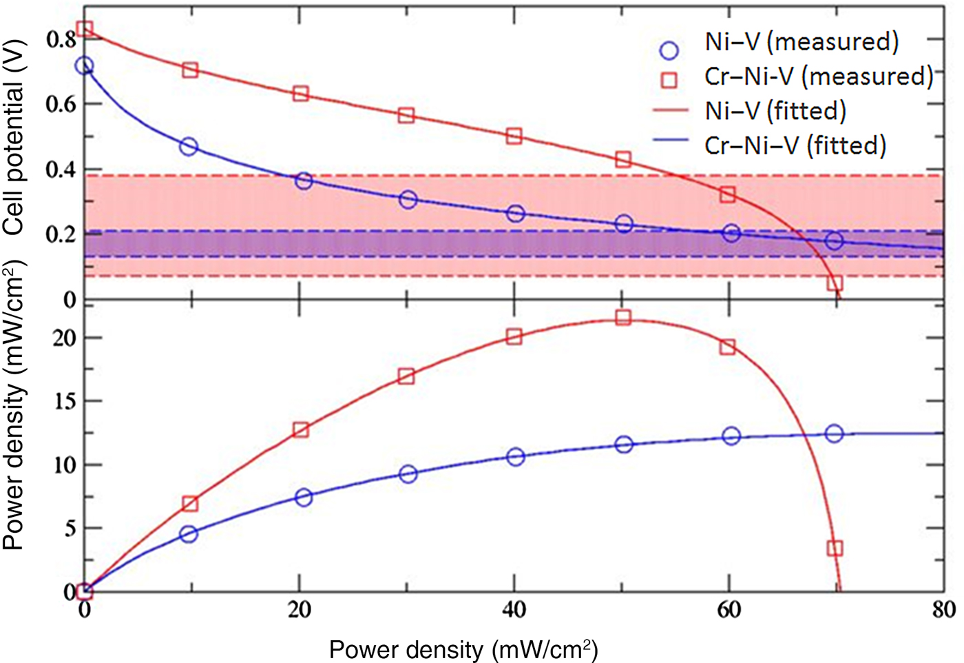
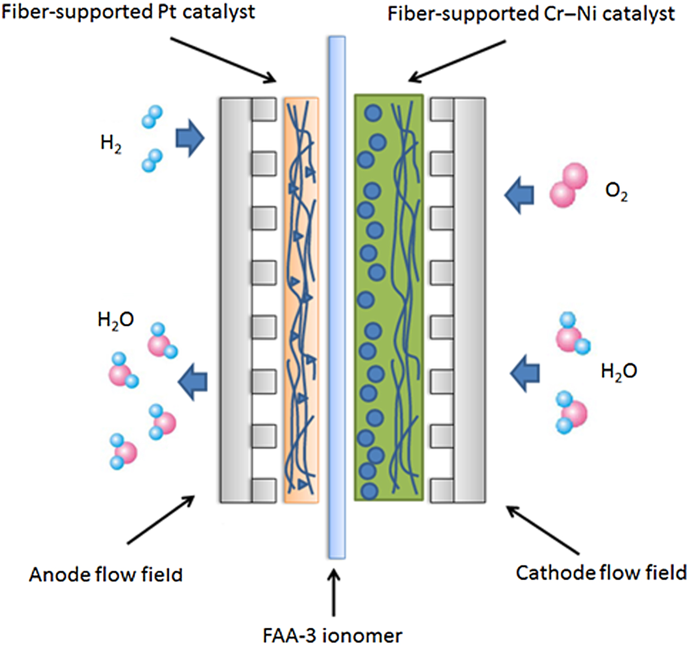
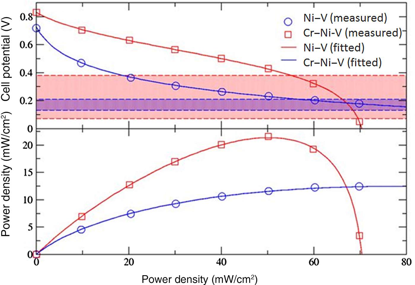
The constructed prototype fuel cell is sketched in Fig. 3. The thicknesses of the ionomer and the Cr–Ni electrode in our setup are 20 and 200 µm, respectively. We carried out polarization curve and power density measurements which are shown in Fig. 4. The measured open-circuit potential is 0.7 V for the cell with the Cr-free cathode. With increasing the current density the cell potential drops logarithmically down to 0.2 V at 70 mA/cm2 reaching a maximum power density of 12.2 mW/cm2. The cell potential with the Cr-Ni cathode starts at 0.8 V (open circuit) and only slightly decays logarithmically in the region up to 20 mA/cm2. Past this current density, the potential decays faster linearly up to 50 mA/cm2. At this point, the cell reaches the maximum power density of 22 mW/cm2 which is an increase of 80% compared with the maximum power density of the Cr-free cell. After this point, both the potential and the power density drop quickly and break down beyond 70 mA/cm2.
Schematic depiction of an APEFC, consisting of a hydroxide ion conductive polymer membrane, a Cr–Ni–V catalyzed cathode, and a Pt-catalyzed anode. O2 is reduced at the cathode in the presence of H2O to produce OH− which is transferred to the anode and reacts with H2 to produce H2O.
Measured and fitted polarization curves and power density of fuel cells with the Ni–V and the Cr–Ni–V electrodes shown in blue and red color, respectively. The dashed lines denote the ranges of the simulated critical potentials U max.
In order to understand the qualitatively different behavior of the two cells, the various contributions to the cell potential loss have to be investigated separately. Therefore we have analyzed the experimentally measured polarization curve using a simple model similar to the cell potential model which has been used recently[ Reference Haji 27 , Reference Motapon, Tremblay and Dessaint 28 ] to decompose the measured polarization curves of a hydrogen/air fuel cell and thus determine the different loss contributions. The model takes into account the activation, the ohmic, and the concentration (mass transport) overpotentials. In this model, the activation and mass transport losses due to the anode processes are neglected. The cell potential is approximated by
 $$\eqalign{U = & U_T - \displaystyle{{kT} \over {e\alpha}} \left[ {\ln (i + i_{\rm loss}) - \ln i_0 + (\alpha + 1) \times \ln \displaystyle{{i_L} \over {i_L - (i + i_{\rm loss})}}} \right] \cr & - {\rm R} \cdot {\rm I}} $$
The thermodynamic potential (the reversible potential) U T is calculated from the standard reversible potential U 0 = 1, 2 V of the ORR at T 0 = 300 K using a modified Nernst equation
 $$U_T = U_0 + \displaystyle{{\Delta S} \over {ne}}(T - T_0) + \displaystyle{{kT} \over {ne}}\ln \displaystyle{{a_{O_2}^{1/2} a_{H_2}} \over {a_{H_2O}}}$$
where n = 2, T = 300 K, ΔS = −163 J/mol/K,
 $a_{H_2O} = 1$
is the activity of liquid water, and
 $a_{H_2}$
and
 $a_{O_2}$
are the partial pressures (in bars) of the two gases, supplied to the anode and the cathode (see specifications in the experimental section), respectively and k is the Boltzmann constant. The number α is the kinetic transfer coefficient, i
0 is the exchange current density, i
L
is the limiting current density due to mass transport limitation, and R is the specific ohmic resistance of the cell. The parameter i
loss takes into account current losses due to leakages and gas diffusion to the counter-electrode through the electrolyte and current due to side reactions. This parameter is effective in the limits of low and high current densities.[
Reference Haji
27
] We performed a non-linear curve fitting shown in Fig. 4 and the fit parameters are summarized in Table II. The model cell potential fits the measured data very well. The relative error in the sum of squares is smaller than 1 × 10⁻⁶ and the correlation coefficient for both curves is larger than 0.999. The transfer coefficient for the Cr-modified electrode is 50% larger than that for the Cr-free electrode. Moreover, the exchange current density with the Cr-modified electrode is with 0.059 mA/cm2 larger. These findings indicate accelerated ORR with the Cr-modified catalyst. At current densities larger than 50 mA/cm2 the ORR is sufficiently fast in the Cr-modified electrode to reach the mass transport limit with limiting current of 78.2 mA/cm2.
Fitted parameters using the experimental polarization curve data and Eq. (1). For the case of the Cr-free electrode the term containing the limiting current density was omitted.

α, kinetic transfer coefficient; i loss, takes into account current losses due to leakages and gas diffusion to the counter-electrode through the electrolyte and current due to side reactions; i 0, exchange current density; i L , limiting current density; R, specific ohmic resistance.
No such limit is found for the cell with the Cr-free catalyst presumably due to the slower ORR kinetics. The specific ohmic resistance of the cell R is very small compared with values found in the literature.[ Reference Haji 27 ] We note that the slope of the linear section recognized visually in the measured data with the Cr-modified catalyst, is a crossover between the kinetic loss and mass transport loss terms rather than a linear potential drop due to ohmic resistance.
Additionally, in Fig. 4 we depicted the ranges of the computed critical potentials U max for the two catalyst types. Neglecting the overpotentials due to the anode and due to non-standard conditions, we find that these ranges are in a good qualitative agreement with the kinetic components of the measured polarization curves.
Conclusions
Following the promising results of theoretical investigations we successfully fabricated a non-precious chromium–nickel–fleece (Cr–Ni–V) electrode with a high-performance APE which is thermally stable up to 120 °C which provides a safe employment in the developed fuel cell prototype. In contrast to some other investigations about radiation-grafted membranes[ Reference Varcoe 29 – Reference Danks, Slade and Varcoe 32 ] this APE can be dissolved in certain solvents, like NMP or alcohol so that it allows an easy casting to membranes of required thickness and additionally ensures a good impregnation into the catalyst layer by getting some catalyst ink. The first test with an ionomer thickness of 20 µm and a 200 µm thick Cr–Ni electrode reveals a very promising power density of 22 mW/cm2. Here we increased the power density of about 80% in contrast to the electrode without Cr (12.2 mW/cm2). Competing with the state-of-the-art PEFC technique, which has been extensively developed for decades, is obviously not the purpose of the present work, but we do see the dawn of AEMFC from this promising result.
Consequently, we can summarize that we tuned the catalytic activity by modifying the carbon supported Ni layer with Cr particles by using an innovative electro spinning fabrication method. Additionally, we combined this flat, non-noble and flexible electrode with an APE in order to create an APE fuel cell with a non-noble catalyst for the ORR. Herby the RDE experiments with the carbon-supported Cr–Ni electrode were carried out with grinding the electrode because the measuring set up was not suited for other methods. Therefore the morphology has to be taken into account for further experiments by designing a setup to ensure a good conductivity without grinding the electrode. Nevertheless, we expect that this work will open up a new avenue to fabricating non-noble catalyst electrodes for the ORR.
Supplementary material
The supplementary material for this article can be found at https://doi.org/10.1557/mrc.2018.13.
Acknowledgments
This work was supported by the Berthold Leibinger Stiftung as a carrier of the Fritz-Hüttinger scholarship and by the Steinbuch Center for Computing. Also Simon Thiele and Carolin Klose from the porous media group of the Department of Microsystems Engineering—IMTEK had made huge efforts on this work. The simulations in this work were performed on the computational resource for HLR I funded by the Ministry of Science, Research and the Arts Baden-Württemberg and Deutsche Forschungsgemeinschaft. J. Erben, Department of Microsystems Engineering IMTEK, Laboratory for MEMS Applications, University of Freiburg, D-79110 Freiburg, Germany.