I. INTRODUCTION
Because of the excellent combination of mechanical property and biocompatibility, titanium alloys are widely used as implant materials for orthopedic applications.Reference Geetha, Singh, Asokamani and Gogia1–Reference Matej, Mark and Waqar3 Among these orthopedic titanium alloys, Ti–6Al–4V (TAV) with α + β microstructure is one of the widely used implant materials to date. However, TAV has several disadvantages such as the toxicity of Al and V, low strength, high elastic modulus relative to human bone, and poor wear resistance.Reference Marc and Rack4 Recently, some near-β type titanium alloys including Nb, Zr, and Ta elements, for example Ti–13Nb–13Zr (TNZ), have been prepared by melt solidification.Reference He and Hagiwara5 These near-β type alloys possess excellent combination of high strength, low elastic modulus, enhanced corrosion resistance, and superior biocompatibility compared with conventional α + β type alloys. Nevertheless, it was found that due to low resistance to plastic shearing and low work hardening of Ti alloys, these near-β type alloys also suffer from the shortcoming of poor tribological property.Reference Rodriguez, Gil and Planell6,Reference Sathish, Geetha, Pandey, Richard and Asokamani7
It is well known that low wear resistance of implant materials results in implant failure because wear debris can be released into the surrounding tissue. This can restrict bone resorption and lead to loosening of implants,Reference Geetha, Singh, Asokamani and Gogia1,Reference Choubey, Basu and Balasubramaniam8 and consequently cause an adverse cellular response leading to inflammation and pain in the body. To avoid this phenomenon, many methods including surface modification and heat treatmentReference Li, Yang, Li, Hao, Cui, Niinomi and Guo9 were used to increase wear resistance of titanium alloy implants. More recently, a biomedical ultrafine-grained (UFGed) Ti65.5Nb22.3Zr4.6Ta1.6Fe6 (TNZTF) composite was developed in our research group by sintering of metallic glass powder.Reference Li, Zou, Yang, Li and Li10 The developed UFGed TNZTF composite has a dual bcc β-type structure, bcc FeTi phase surrounded by bcc β-Ti matrix, exhibiting a high fracture strength of 2650 MPa along with a low Young's modulus of 52 GPa, respectively. Because of increasing osteoblast adhesion of UFGed structure,Reference Webster and Ejiofor11 it is expected that the UFGed TNZTF composite has a better biomechanical compatibility compared to its coarse-grained counterpart. However, its tribological behavior should be further addressed to exploit its application as implant materials.
In the present work, unusual tribological behavior of biomedical UFGed TNZTF composites developed was investigated under different sliding speeds and applied loads. The results obtained show that the UFGed composites have far better wear resistance compared with two kinds of conventional biomedical titanium alloys, the TAV and TNZ alloys. The excellent tribological property provides a possibility that the TNZTF alloys can be used as implant materials for orthopedic applications in the future.
II. EXPERIMENTAL
A. Materials
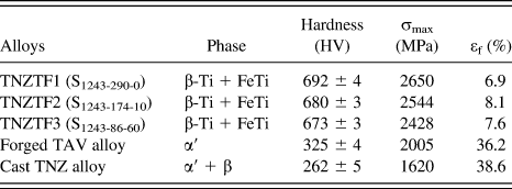
The UFGed TNZTF alloy was fabricated by powder consolidation and crystallization of amorphous phase using spark plasma sintering (SPS). First, glassy TNZTF alloy powder was synthesized from respective element powders by mechanical alloying. The subsequent sintering experiment for the synthesized glassy powder was accomplished under a protective atmosphere of argon by a SPS-825 system (Sumitomo Coal Mining Co. Ltd, Tokyo, Japan). The detailed procedure of synthesis of glassy powder and consolidation by SPS can be seen in elsewhere.Reference Zou, Yang, Long, Xiao and Li12–Reference Li, Yang, Chen, Li and Zhu15 To investigate the effect of grain size on wear resistance, the sintering parameters were selected as heating to 1243 K with different heating rates and holding times (Table I). According to previous results, the three kinds of TNZTF alloys have different grain sizes fabricated at different sintering parameters.Reference Li, Zou, Yang, Li and Li10 All sintered bulk alloys have a cylindrical shape with a dimension of φ20 mm × 8 mm. Two kinds of biomedical reference alloys, the forged TAV and cast TNZ alloys in the form of cylindrical bars with a diameter of 40 mm, were supplied by Northwest Institute for Nonferrous Metal Research, China.
The phase constitution of the three kinds of samples was confirmed by x-ray diffraction (XRD) (D/MAX-2500/PC; Rigaku Corp., Tokyo, Japan) with Cu Kα radiation. Vickers hardness, by calculating the average value of eight tests, was measured using a HVS-1000 microhardness tester (Wolpert Wilson Instruments, Norwood, MA) with a load of 49 N and a dwell time of 20 s. Microstructures of the three kinds of samples were observed by a scanning electron microscope (SEM) (NOVA NANOSEM430, FEI, Hillsboro, OR) and a Tecnai G2 F30 field emission gun transmission electron microscope (TEM) (FEI). The mechanical properties of the alloys were tested by uniaxial compression using an MTSTestStar 810 testing system according to the ASTM standards. The detailed phase constitution and mechanical properties of the three kinds of titanium alloys were listed in Table I.
Phase constitution and mechanical properties of the three kinds of titanium alloys. The subscripts x, y, and z in the TNZTF alloy ‘S x-y-z’ denote sintering temperature, heating rates, and holding time, respectively.

B. Wear tests
The dry wear tests were used to evaluate friction performance. The wear tests were performed on a block-on-disc wear testing machine according to ASTM standard G77-83. The test specimens with a dimension of 10 × 10 × 3 mm cut from the three kinds of samples were used as static blocks. Before tests, the blocks were mechanically ground and then polished to a roughness (R a) of 0.2 µm. The rotating friction pair was made of case-hardened GCr15 steel disc with 47 mm in diameter and 10 mm in thickness (surface hardness = 720 HV). The roughness of the ground contact surface was R a = 0.49 µm. The blocks and disc were cleaned ultrasonically using acetone. The applied normal load (F n) was selected as 70, 130, and 200 N, respectively. During the tests, the rotating speed of the disc was 0.5 and 1.0 m/s, respectively.
Based on the wear tests performed by Cvijović-Alagić,Reference Cvijović-Alagić, Cvijović, Mitrović, Rakin, Veljović and Babic16 the wear characteristics were evaluated by the volume loss of the blocks after sliding of 60 min when a steady-state condition has been attained. The worn surface morphology of tested blocks was observed using SEM (Quanta 2000, FEI). Worn surface chemical composition was analyzed by x-ray photoelectron spectroscopy (XPS, Axis Ultra DLD, Kratos, England) in a vacuum chamber at a base pressure of 6.7 × 10⁻⁷ Pa. A standard Al Kα excitation source (hv = 1486.6 eV) was used. Prior to testing, an unavoidable 5-nm-thick surface contamination layer was removed by sputtering with a cold cathode Ar+ ion gun (2.5 kV, 4 μA) at an angle of 50°. The binding energy (BE) scale was calibrated by measuring the reference peak of C 1s (BE = 284.6 eV) from the surface contamination.
III. RESULTS AND DISCUSSION
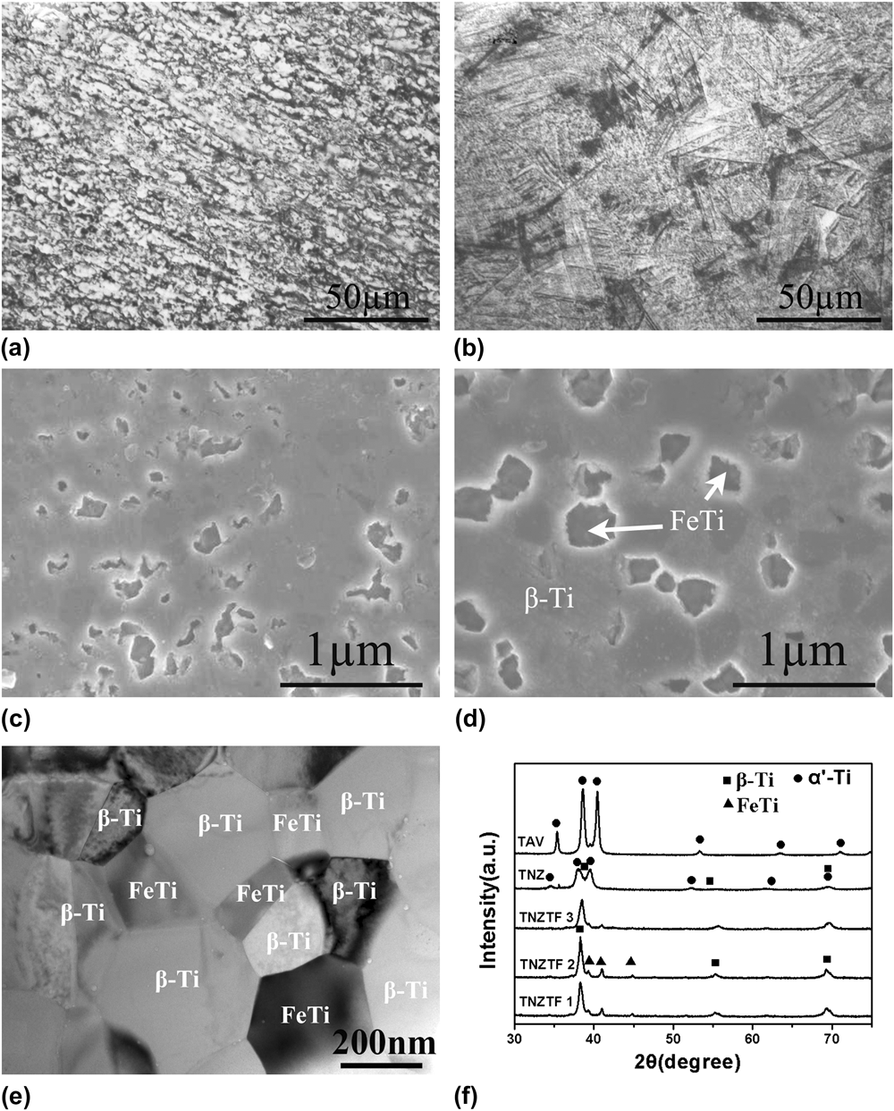
Figure 1 shows SEM microstructure and XRD patterns of the three kinds of titanium alloys. The microstructure of the TNZTF alloys contains a bcc FeTi region surrounded by bcc β-Ti matrix [Figs. 1(c)–1(e)]. Meanwhile, the grain size, or the scale of the two-phase region increases with the increase in holding time. Further TEM examination proves that the grain size in the TNZTF alloys is less than 1 µm [Fig. 1(e)]. Because of the increased grain size resulting from the decreased heating rate and increased holding time,Reference Li, Zou, Yang, Li and Li10,Reference Li, Yang, Qu, Li and Chen17 the grain size in the TNZTF1, TNZTF2, and TNZTF3 samples increases correspondingly. In contrast, the forged TAV alloy consists of a microstructure of α′ lamellae [Figs. 1(a) and 1(f)]; the cast TNZ alloy is composed of acicular α′ phase and β phase [Figs. 1(b) and 1(f)].Reference Cvijović-Alagić, Cvijović, Mitrović, Panić and Rakin18
SEM microstructures of alloys: (a) the forged TAV alloy, (b) the cast TNZ alloy, (c) the TNZTF1 alloy, and (d) the TNZTF2 alloy, respectively. (e) TEM microstructure of the TNZTF3 alloy. (f) XRD patterns of the three kinds of titanium alloys.

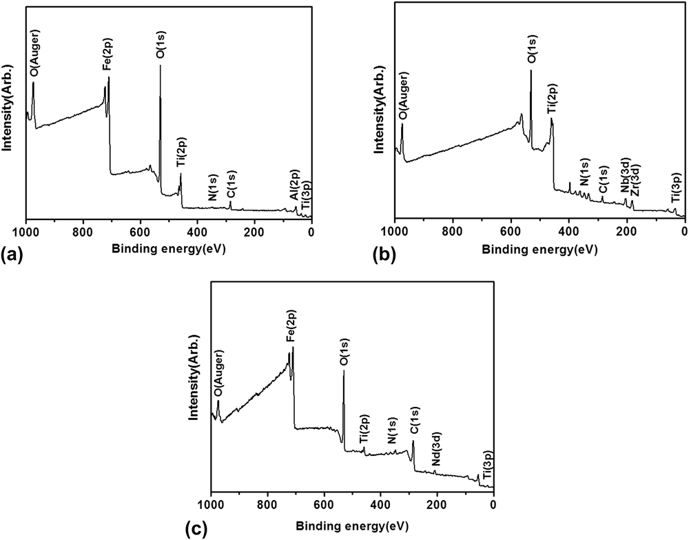
Figure 2 presents XPS spectra of the worn surfaces of the three kinds of titanium alloys. Obviously, all samples exhibit a wide scanning spectrum for qualitative analysis. It is found that all worn surfaces include formed TiO2. Besides, the worn surface of the TNZTF1 alloy covers Nb2O5 and Fe2O3. The amount of the Zr and Ta-containing oxides is very small, so they cannot be detected. For the TAV alloy, the worn surface contains Al2O3 and Fe2O3. As for the TNZ alloy, the worn surface includes Nb2O5 and ZrO2. It should be noted that the Fe2O3 resulted from the GCr15 steel disc. In addition, a small amount of N detected comes from impurity for the three kinds of the worn samples.
XPS spectra of the worn surfaces of the three kinds of titanium alloys: (a) the TAV alloy, (b) the TNZ alloy, and (c) the TNZTF1 alloy, respectively.

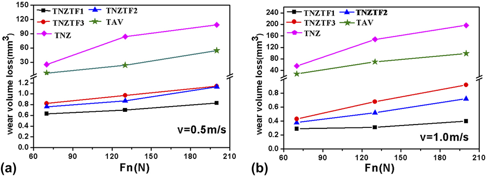
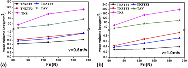
Figure 3 displays wear loss of the three kinds of titanium alloys under different applied loads and sliding speeds. Apparently, the wear loss increases with the increase in applied load. For the three kinds of titanium alloys, wear resistance increases from the TNZ and TAV alloys to the TNZTF alloy. The variation in the wear loss is TNZTF3 > TNZTF2 > TNZTF1, in agreement with the change in grain size for the three TNZTF samples. This means that the higher hardness caused by the smaller grain size gives rise to the stronger wear resistance in the TNZTF alloys (Table I). The results obtained here are consistent with the Archard's law. In other words, the wear resistance of materials is proportional to their hardness values.Reference Archard19 It should be noted that the wear loss of the TNZTF samples is only 3.5% and 1% of that of the TAV and TNZ samples, respectively. The outstanding tribological property proves that the TNZTF alloy is an excellent candidate material used for biomedical application.
Wear loss of the three kinds of titanium alloys under different applied loads at the sliding speeds of (a) 0.5 m/s and (b) 1.0 m/s, respectively.

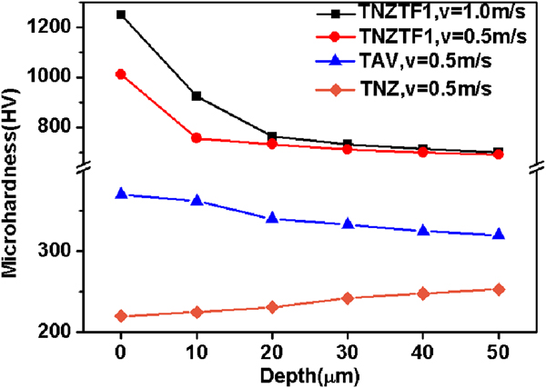
Surprisingly, the wear loss of the TNZTF alloy decreases with the increase in sliding speed at the same load (Fig. 3). This has never been reported so far in titanium alloys. To explain this unusual tribological behavior, the microhardness of the three kinds of titanium alloys along the cross-section perpendicular to the worn surfaces under sliding speeds of 0.5 m/s and 1.0 m/s at an applied load of 130 N was measured and presented in Fig. 4. It is well accepted that the temperature rise generated by friction on the worn surfaces is higher under higher sliding speed at the same load. This can also be proved by the bluing of the worn surfaces of the TNZTF1 samples at a sliding speed of 1.0 m/s. Under this circumstance, hard oxide particles with larger amount, such as TiO2 and Nb2O5 [Fig. 2(c)], are easy to form on the worn surfaces for the TNZTF1 sample. This is very helpful for increasing the hardness of the worn surfaces.Reference Li and Xiao20 It can be seen from Fig. 4 that the hardness of the worn surface in the TNZTF1 sample at a sliding speed of 1.0 m/s is 250 HV higher than that at 0.5 m/s. Also, these hardness values are higher than that of the GCr15 friction pair (HV = 720). Therefore, the higher worn surface hardness at 1.0 m/s can lead to the stronger wear resistance and consequently cause less wear loss (Fig. 3). On the other hand, the thickness of plastically strained subsurface layer increases with the increase in sliding speed.Reference Molinari, Straffelini, Tesi and Bacci21 The deformation in the subsurface layer results in strain hardening. Namely, sliding wear in ductile materials may produce large amounts of plastic deformation in the material layers adjacent to contact surfaces. This also can cause an increase in the hardness of the sliding worn surfaces.Reference Cvijović-Alagić, Cvijović, Mitrović, Panić and Rakin18 In short, the hardness increase resulting from these two aspects, larger amounts in formed hard Nb2O5 particles and more severe plastic deformation in the subsurface layer, causes the decrease in the wear loss of the TNZTF alloy with the increase in sliding speed at the same load of 130 N (Fig. 3). For the TAV alloy, the temperature rise generated by friction on the worn surfaces is far lower than that of the TNZTF alloy under the same sliding speed and applied load because of its relative low hardness. Hence, its hardness value of the worn surface added by formed hard oxide particles, 50 HV, is far less than that of the TNZTF alloy. Meanwhile, it has been proved that compared with TiO2, Nb2O5 is a very good lubricating and hard oxide.Reference Li, Yang, Li, Hao, Cui, Niinomi and Guo9 This indicates that the presence of formed hard Nb2O5 particles on the worn surface of the TNZTF alloy (Figs. 2 and 3) is another reason contributing to the higher hardness in the TNZTF alloy (Fig. 4). As for the TNZ alloy, the hardness value of the worn surface drops to 220 HV from the matrix hardness of 262 HV. This drop in the hardness is attributed to the occurrence of a thermal softening effect.Reference Straffelini and Molinari22
Variation of microhardness with the depth away from the worn surfaces for the three kinds of titanium alloys under different sliding speeds at an applied load of 130 N.

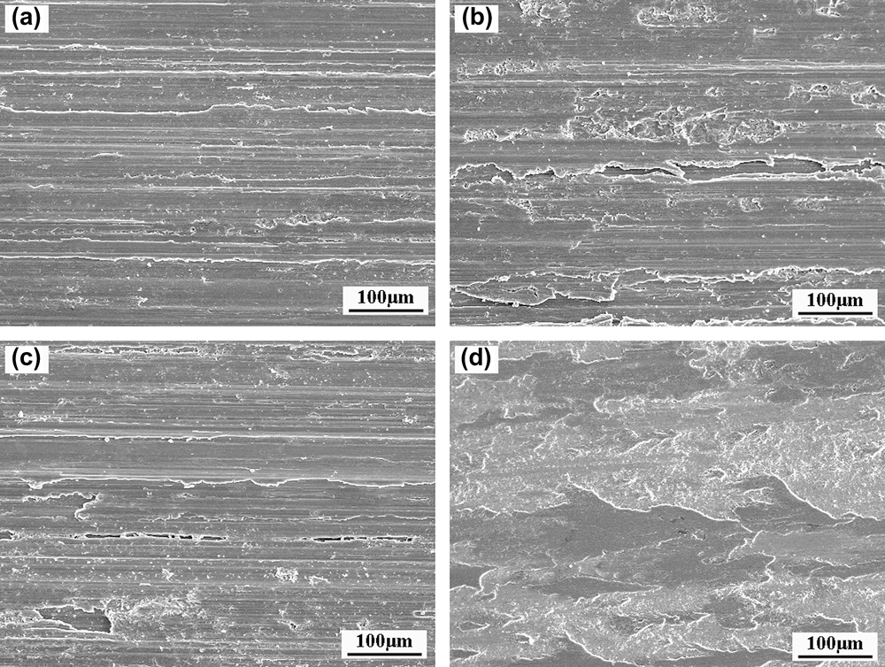
Figure 5 shows SEM micrographs of the worn surfaces of the TNZTF1 alloys under different sliding speeds and applied loads. Under a sliding speed of 0.5 m/s and applied load of 70 N [Fig. 5(a)], the worn surface morphology indicates that noticeable plastic deformation and plow aligned the direction of sliding forms. This means that the corresponding wear mechanism is abrasive wear.Reference John and Burwell23 With the increase in sliding speed and applied load [Figs. 5(b) and 5(c)], the groove on the worn surfaces becomes deeper. Moreover, the existence of material delamination strongly suggests the occurrence of adhesive wear. The long tongue shaped structure caused by plastic flow is visible in the plow position. With further increase in the sliding speed and applied load [Fig. 5(d)], the adhesion phenomenon is more serious and large area of peeling layer appears. No cracks are observed in our case, revealing heavy smearing of the worn surface and removal of the formed transfer layer.Reference John and Burwell23
SEM micrographs of the worn surfaces of the TNZTF1 alloys under different sliding speeds and applied loads: (a) v = 0.5 m/s and F = 70 N, (b) v = 1.0 m/s and F = 70 N, (c) v = 0.5 m/s and F = 200 N, and (d) v = 1.0 m/s and F = 200 N, respectively.

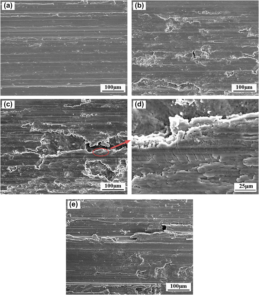
Figure 6 shows SEM micrographs of the worn surfaces of the TAV alloys under different sliding speeds and applied loads. Similar to the TNZTF1 alloy, wear grooves along the sliding direction and signs of plastic deformation emerge under a sliding speed of 0.5 m/s and applied load of 70 N [Fig. 6(a)]. This implies a wear mechanism with a predominant characteristic of abrasion wear. With the increase in sliding speed and load, the wear mechanism changes into adhesive wear [Figs. 6(b)–6(e)]. Compared with the TNZTF1 alloy, the delamination and smearing phenomenon becomes more severe (Figs. 5 and 6) because of its lower hardness. This is consistent with the far bigger wear loss of the TAV alloy under the same sliding speed and applied load (Fig. 3). Moreover, when the applied load is increased to 200 N, microcracks appear because accumulated plastic strain exceeds a critical value [Fig. 6(d)]. This means that a fatigue wear mechanism overlapped with adhesive wear under this condition.Reference John and Burwell23 Under higher sliding speed [Fig. 6(e)], the occurrence of adhesion wear is more prominent. However, a large number of brittle flakes enhance the delamination phenomenon under rolling of friction contact. This has also been reported that adhesive wear is a principal mechanism for the TAV alloy under dry wear condition.Reference Long and Rack24
SEM micrographs of the worn surfaces of the TAV alloys under different sliding speeds and applied loads: (a) v = 0.5 m/s and F = 70 N, (b) v = 1.0 m/s and F = 70 N, (c) and (d) v = 0.5 m/s and F = 200 N, (e) v = 1.0 m/s and F = 200 N, respectively. (d) The magnified area in (c) is marked by the oval.

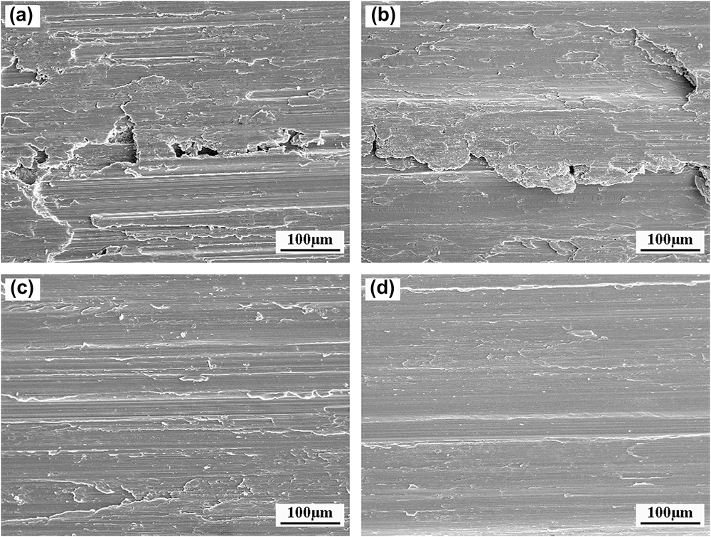
Figure 7 presents SEM micrographs of the worn surfaces of the TNZ alloys under different sliding speeds and applied loads. Differently from the TNZTF and TAV alloys, it is found that severe adhesion wear damage appears even at the lowest sliding speed and applied load because of its relative low hardness [Fig. 7(a)]. With the increased sliding speed to 1.0 m/s at an applied load of 70 N, the delamination area enlarges with peeling of bulk materials and removing of large flakes from the worn surfaces [Fig. 7(b)]. The wide range removing of materials by adhesion wear is related to large wear loss of the TNZ alloy (Fig. 3). With the increased applied load to 200 N [Figs. 7(c) and 7(d)], the worn surfaces are heavily compacted by the GCr15 steel disc roller and hence severe plastic deformation takes place. This gives rise to that the transfer layers in the form of bulk materials are detached from the worn surfaces by adhesion to the GCr15 steel disc counterpart. Consequently, no microcracks or delamination can be observed on the worn surfaces. Obviously, the tribological behavior of the TNZ alloy strongly depends on its relative low hardness.
SEM micrographs of the worn surfaces of the TNZ alloys under different sliding speeds and applied loads: (a) v = 0.5 m/s and F = 70 N, (b) v = 1.0 m/s and F = 70 N, (c) v = 0.5 m/s and F = 200 N, (d) v = 1.0 m/s and F = 200 N, respectively.

IV. CONCLUSIONS
Unusual tribological behavior of biomedical UFGed TNZTF alloys fabricated by powder metallurgy was investigated under dry wear condition. A far better wear resistance for the TNZTF alloys is found compared with the TAV and TNZ alloys. Unusually, the wear loss of the TNZTF samples decreases with the increase in sliding speed at the same load. This is attributed to larger amounts in formed hard Nb2O5 particles and more severe plastic deformation in the subsurface layer. Meanwhile, due to UFGed structure and high hardness, the wear mechanism of the TNZTF alloys transforms from abrasive wear to adhesive wear with the increase in sliding speed and applied load. The outstanding wear resistance provides a possibility that the UFGed TNZTF alloys can be used as candidate materials for biomedical application.
ACKNOWLEDGMENTS
This work was supported by the Guangdong Natural Science Foundation (No. S2013010012147), the Science and Technology Innovation Project of Higher School of Guangdong Province (No. 2012KJCX0010), the Fundamental Research Funds for the Central Universities (No. 2013ZZ0008), the Program for New Century Excellent Talents in University (No. NCET-11-0163), and open fund from National Engineering Research Center of Near-net-shape Forming for Metallic Materials (No. 2013007).