1. Introduction
The subglacial deforming-till/sliding-till model has been used to explain many sedimentological features (Reference BoultonBoulton, 1996), but has not yet been extensively used in physically based models to determine whether it can predict typical subglacial landforms. The idea that drumlin seeding and shaping is a consequence of the viscous-like flow of subglacial till dates back at least to the mid-1980s (Reference Boulton, Menzies and RoseBoulton, 1987; Reference MenziesMenzies, 1989; Reference HartHart, 1997). Recently, this idea has been formulated in some physically based models and two significant theoretical aspects have emerged. Firstly, the subglacial flow of till is prone to so-called “shock” formation, which means that jumps in the till thickness emerge spontaneously if relief is already present. Reference HindmarshHindmarsh (1996, Reference Hindmarsh1998a) argues that these “shocks” manifest themselves as the blunt faces of drumlins. Secondly, the coupled flow of ice and till is conditionally unstable (Reference HindmarshHindmarsh, 1998b, Reference Hindmarshc; Reference FowlerFowler, in press). This means that under certain conditions small undulations in till thickness grow, causing relief to appear spontaneously. This is known to occur at short wavelength (till length less than ice thickness) and at long wavelength (till length much greater than the ice thickness). Here, wavelength refers to the horizontal scale of a disturbance in the till thickness or, later on, the bedrock profile. This conditional stability shows a complex dependence on parameters describing the subglacial physical environment and geometry, and the till rheology. The hydrodynamic hypothesis subscribed to in this paper is that drumlins are seeded through this instability mechanism and shaped into drumlinoid forms through the shock-formation mechanism.
This idea needs to be validated by non-linear computation of coupled ice and till flow, but many issues are raised by the studies already discussed, essentially relating to the robustness of the hydrodynamic hypothesis. This paper seeks to explore the robustness and explicative power of the hydrodynamic hypothesis by using and extending the mathematical analyses of Reference HindmarshHindmarsh (1998b, Reference Hindmarshc). There are four themes: (1) We consider some of the large-scale observational consequences of predictions that coupled ice—till flow is unstable (Reference HindmarshHindmarsh, 1998b, Reference Hindmarshc) and can generate relief. Such instabilities tend to create relief at a particular wavelength and presumably produce fields of similar drumlins, a feature that is commonly observed. Variations (Reference Hättestrand, Goodwillie and KlemanHättestrand and others, 1999) comprise two populations superimposed upon one another (these authors suggest that the particular drumlins are “erosional” but do not present evidence which excludes erosion by deformation). We discuss whether the hydrodynamic hypothesis can explain drumlin-field phenomena, paying particular attention to rates of drumlin growth; (2) We examine the robustness of the hydrodynamic hypothesis to a further physical process, ice—till slip. Reference Iverson, Jansson and HookeIverson and others (1994) and Reference Engelhardt and KambEngelhardt and Kamb (1998) have emphasized that ice—till slip may be more significant than hitherto realized. Sliding at the till—bed interface is discussed and introduced into the models. Stability analyses are carried out with extra sliding physics incorporated, with basal motion apportioned between TBS (till—bed sliding) (Reference Cuffey and AlleyCuffey and Alley, 1996; Reference HindmarshHindmarsh, 1996), TID (till internal deformation) and ITS (ice—till sliding) (Reference Iverson, Hanson, Hooke and JanssonIverson and others, 1995). The present paper attempts to answer the question of how much slip affects the stability properties of the coupled ice—till— water system at these interfaces; (3) We examine in detail how the flow patterns around till bumps can act to cause till relief to grow; (4) Deforming till acts as an abrasive agent and can thus modify bedrock shape. We examine whether the hydrodynamic hypothesis is consistent with observations of subglacial bedrock erosion.
Amplification of relief in eroding bedrock (through slip at the till—bed interface) seems to be necessary to explain whale- backs (sometimes called rock drumlins), which are smooth forms sometimes tens of metres high and hundreds of metres long which have been shaped by glacial erosion (Reference EvansEvans, 1996). When they have shattered lee sides, they are known as roches moutonnées. The problem of ice abrading bedrock bumps has been examined previously by Reference Boulton and CoatesBoulton (1974) who, possibly somewhat inconsistently, used the Nye—Kamb (NK) solution for perfect slip (Reference NyeNye, 1969, Reference Nye1970; Reference KambKamb, 1970).We consider cases where there is frictional retardation at the bed.
Valley steps have been “created” in models by Reference OerlemansOerlemans (1985) and Reference MazoMazo (1989), but equivalent features (long wavelength undulations) are not reported from regions of areal scour. Oerlemans’ model is non-linear, and creates valley steps through preferred long-term occupation of hollows (a stable margin position when ablation varies with elevation) by erosive glacier margins. Mazo’s model is an infinite plane model, as in this paper, but uses a different basal physics.
Modelling is carried out at two horizontal-length scales; (1) where the wavelengths are much less than the ice thickness and (2) where the wavelengths are much greater than the ice thickness. The mathematical details are very similar to those presented in previous papers; some extensions relating to ice—till slip and the presence of bedrock undulations are outlined briefly in the appendices. The opportunity is also taken to examine whether variation of shear stress with depth within the till significantly affects the coupled dynamics, as it adds a diffusive and presumably stabilizing term to the model.
2. Formulation of Coupled Ice-Till Flow Models: Physical Description
The physical situation we are considering is of viscous ice lying on top of a layer of viscous till, which in turn overlies some bedrock (Fig. 1). The bedrock cannot deform, but TBS can cause abrasion of the bedrock. Bumps can exist in either the till surface or bedrock surface and in both. The ice is in motion and the ice exerts a tangential force on the till. Two cases are considered. (1) A generalization of Reference HindmarshHindmarsh’s (1998b) NK solution, which is appropriate for cases where the wavelength of the bump is very much less than the ice thickness. A perturbed form of the Stokes equations is solved by approximating ice as a Newtonian fluid. (2) When the shallow ice approximation (Reference HutterHutter, 1983; Reference MorlandMorland, 1984; Reference FowlerFowler, 1992) is appropriate, where the wavelength is greater than the bump thickness. Both cases utilize solutions where the flow domain is infinite in the longitudinal extent, and consists of a sinusoidal bed with wavelength L.
Illustrating the configuration used in the computations. The section, one wavelength 2π/k long, is repeated up-and downstream, and shear (short wavelength) or body forces (long wavelength) cause coupled motion of the ice and till. Variation in the stress fields causes variation in the till flux, which can cause till relief to grow. These can also cause variation in the abrasion rate and bedrock forms to grow. At short wavelength the ice surface is not included, as it is too distant to affect the situation.

It is reasonable to raise the objection that soil-mechanical ideas, which date back to Terzaghi in the 1920s, view till as a plastic material and that viscous models are not justified by the evidence. In the 1980s, glaciologists began to think that plastic models were not an adequate description of the coupled deformation of glaciers overriding till and suggested viscous relations, some of which included dependence on the effective pressure (Reference Alley, Blankenship, Rooney and BentleyAlley and others, 1987; Reference Boulton, Menzies and RoseBoulton and Hindmarsh, 1987; Reference ClarkeClarke, 1987). More recently, detailed observations in areas away from glacier margins suggest the picture is more complicated and there have been renewed suggestions that till behaves plastically (Reference Engelhardt, Humphrey, Kamb and FahnestockEngelhardt and others, 1990; Reference KambKamb, 1991), or at least in a manner more complex than viscous (Reference Iverson, Jansson and HookeIverson and others, 1994; Reference Murray and ClarkeMurray and Clarke, 1995). These observations were on the small-scale and there have been arguments proposed (Reference Bahr and RundleBahr and Rundle, 1996; Reference HindmarshHindmarsh, 1997) that the two views are reconcilable; on the small scale, till behaves plastically, while on the large scale, till behaves viscously. The argument is that if on the large scale, modelling of till as a viscous fluid produces the correct glacial geomorphology, it is a possible description at least on the large scale. Thus, the modelling in this paper can be regarded as a test of the viscous theory.
Since we are dealing with a linearization, a base case (or unperturbed solution) must be specified. This is a till layer of uniform thickness, D 0, shearing under the effect of the glacially applied shear with a velocity distribution that is independent of horizontal position. The ice is in the half-space z > 0, where z denotes vertical position. Computation of the velocity distribution within the till then simply involves an integration over the vertical direction. The bedrock elevation is —D0.
We then consider the case where the till surface is slightly perturbed, that is its surface is no longer exactly flat but contains small variations with horizontal position. The ice is now in the half-space z > D + f 1 — D 0, where D is the till-sheet thickness, and f 1 (x, t) — D 0 is the bedrock elevation. The slight perturbation is an assumption of the mathematical technique (the linearization) used. By assessing the stability of the solutions, one determines whether a small variation superimposed on a uniform till sheet grows or shrinks. If, for example, an increased thickness causes the effective pressure to increase, then the zone where the sediment is thicker will move more slowly and sediment will accrete here. If it continues to accrete locally, the thickness deviation will eventually become so large the linear approximation is no longer valid. At this point, non-linear behaviour determines what happens next. One near certainty is shock formation, which in general causes the maximum relief of the till sheet to decrease (Reference HindmarshHindmarsh, 1998a). Mathematically, this is a jump in the till thickness with the implication that, in the field, one would observe steep faces (e.g. the blunt end of a drumlin). What else happens can only be determined by (almost certainly numerical) solution of the non-linear equations. However, one can say that in this unstable case, the final outcome cannot be a flat till sheet, because if the relief decayed, at a certain point the variations would become sufficiently small that their behaviour would be adequately described by the linear approximation, and the linear instability would reassert itself. Thus, where there is instability, we expect there to be some observable manifestation of the fact that the till-sheet flow is unstable.
In fact, we can be a bit more specific about the minimum size of the features that arise as a result of the non-linear instability. Let us suppose that the till sheet has a thickness of D 0, and let us consider a perturbation of size D 1. Then, standard theory (specifically the Taylor expansion) shows us that the relative error in the solution for the perturbation is D 1/D 0. While this number remains small, say less than 20%, the dominant behaviour will be that predicted by linear theory. We can thus say that if the till-sheet flow is unstable, then the resultant variation in thickness will be, at the very least, around 20% of the till-sheet thickness.
We also consider the abrasive effect of till sliding over bedrock and consider the abrasive effect of debris-bearing ice sliding over bedrock with friction. In these studies, we determine whether bumps in the bedrock will grow or shrink. The interest here lies in establishing whether the present model can also produce successful predictions of bedrock relief growth; the Mazo and Oerlemans models do not consider till deformation and thus do not address the issue of drumlin formation.
The mathematical formulation of the models is discussed in detail by Reference HindmarshHindmarsh (1998b, Reference Hindmarshc). The velocities and fluxes are computed following Reference AlleyAlley (1989) and Reference HindmarshHindmarsh (1998a). Till flux can arise either from internal deformation within the till or from till sliding over the base. When considering internal deformation, the strain rate in the till is given by a double power-law rheology (Reference Boulton, Menzies and RoseBoulton and Hindmarsh, 1987) where the shear strain-rate δ zu depends upon the applied shear stress τ and the effective pressure p e (x, z)

where A d is a rate factor and a and b are parameters. The velocity u is a function of x and z. By integrating with respect to z over the interval f i — D 0 ≤ z ≤ f i + D — D 0, we can obtain relations for the till velocity u(x, z) and the till flux q(x). The formulae are given by Reference HindmarshHindmarsh (1998b; Equations (15) and (16)). These integrals depend upon g, the acceleration due to gravity, ρ i, ρ w and ρs are the densities of ice, water and sediment grains, and ϕ is the porosity of the sediment. We use the values 9.81 ms2, 1.0 × 10³ kg m—3, 0.917 × 10³ kg m—3, 2.7 × 10³ kg m—3 and 0.2 respectively in this paper.
We now turn our attention to till—bed sliding. We use the viscous-type sliding law proposed by Reference HindmarshHindmarsh (1996)

Finally we consider ice—till sliding. Again, a typical viscous type sliding law (e.g. Reference BindschadlerBindschadler, 1983) is used

which obviously does not affect the till flux. Here, A r, s are rate factors and c r, s, d r, s are indices.
The linearized model (see Reference HindmarshHindmarsh, 1998b, Reference Hindmarshc) is defined by writing

where q is the till flux and μ is a small parameter, and we construct similar expansions for the shear stress τ and the effective pressure ρe0. The latter refers to an effective pressure determined by a hydraulic theory and is discussed by Reference HindmarshHindmarsh (1998a). The model is constructed in terms of the quantities


Formulae for some of these derivatives are given by Hind- marsh (1998b, Equation (19)). Perturbed velocities are given by

and perturbed fluxes by

where  are the tangential and normal tractions and f
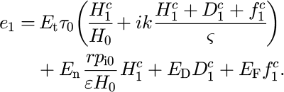
1 is the bedrock elevation. Finally, in order to model the evolution of bedrock relief, we need an abrasion relationship and we follow numerous authors (e.g. Reference RabinowiczRabinowicz, 1965) in suggesting that the rate of erosion be proportional to the product of sliding velocity and normal stress

where g is a phenomenological constant. Values of this are not known, but this does not matter in the present analysis as we are interested in spatial variations oferosion rates and not absolute values. The erosion perturbation e i is given by


Here, δ =(ρw—ρi)g, r ={(1—ø)ρs + øρw — ρi}g. We shall use these relationships to determine whether abrasion can cause relief to become amplified. We also have the derivatives with respect to the bedrock profile (R f, Q f) = (ρw — ρi) g (R n, Q n).
2.1. Nye—Kamb solution for short wavelengths
The Nye—Kamb solution (Reference NyeNye, 1969, Reference Nye1970; Reference KambKamb, 1970) considers the case of infinitely deep ice overlying a bump with an infinity of clones upstream and downstream, and is a good approximation when the wavelength of the bump is much less than the ice thickness. The NK solution assumes a frictionless bed, but has been extended by Reference HindmarshHindmarsh (1998b) to consider a shearing flow of ice with friction at the bed and the flow of ice over a deforming bed, under a shear stress of r 0 and a ice basal-velocity of u 0. Let us suppose that the till-thickness profile perturbation is given by a sinusoidal profile (Fig. 1)

where k is a wavenumber and  is a complex function of time t. Other quantities with superscript c play corresponding roles as Fourier coefficients
 By adopting a complex variable formulation, we may follow Reference HindmarshHindmarsh (1998b) and show that the ice and till velocity fields can be written in terms of complex coefficients C
c, P
c which are solutions of the linear equation

where η is the Newtonian viscosity of ice and compute the growth rate of till relief from the formulae

and  tells us whether the sheet flow is unstable or not. Let us denote the basal (i.e. bedrock) topography by z = fc exp(-ikx). It is shown in the Appendix A how to compute the solution fields in the presence of basal topography, and thence the steady till thickness and the corresponding abrasion rate (Appendix B). We shall consider in more detail the effect of introducing sliding at (1) the base of the till, i.e. at the till—bedrock interface; and (2) at the base of the ice, at the ice—till interface.
Shallow ice approximation for long wavelengths
This case is appropriate for length scales L greater than the ice thickness H 0. In these experiments, we have an infinite plane of slope ε down which ice is flowing, slipping over the till, causing the till to deform internally and causing slip to occur between till and bed. The configuration is described in more detail in Reference HindmarshHindmarsh (1998c); in particular, the basal shear stress is given by the usual formula |τ0| = ρigH 0 ε. A series of related perturbations of the flow of ice down the infinite plane are discussed by Reference PatersonPaterson (1994). In these experiments, we consider the effect of slip of ice over till on the proportion of unstable modes and examine the question of relief amplification of bedrock being abraded by sliding till. (A mode is a concept from linear theory and refers to behaviour at a given spatial scale which possesses a growth rate λ, which determines the exponential rate of growth of the phenomena, e.g. the dynamics of a quantity θ are defined by θ = λθ). In these experiments, the interfacial effective pressure is set constant even when bed perturbations are introduced, which is appropriate for long length scales (Reference HindmarshHindmarsh, 1998c). This model can be recast in terms of complex exponentials in a similar way as Equation (9)

where k is a wavenumber D 1, H 1 and f 1 are the till-thickness, ice-thickness and bedrock-surface perturbations. The mode evolution equation for ice thickness is

and till thickness is

Where

Apart from the introduction of ice—till slip and bedrock abrasion (Appendix B), Reference HindmarshHindmarsh’s (1998c) model is improved by including the variation of shear stress with depth in the till. This could have been significant because the stability of the system is marginal in a number of cases. The mathematical details will be given in a future paper. In the numerical computations carried out here, it was found that the difference between these results and those discussed by Reference HindmarshHindmarsh (1998c) were relatively small, because while the variation of shear stress with depth introduced by the weight of the till is diffusive (and therefore stabilizing), there is also a variation induced by the force gradient within the ice which can either be stabilizing or non-stabilizing. Reference FowlerFowler (in press) appears to reach the conclusion that this essentially diffusive process stabilizes the system uniformly.
3. Physical Mechanisms for Generating Instabilitie
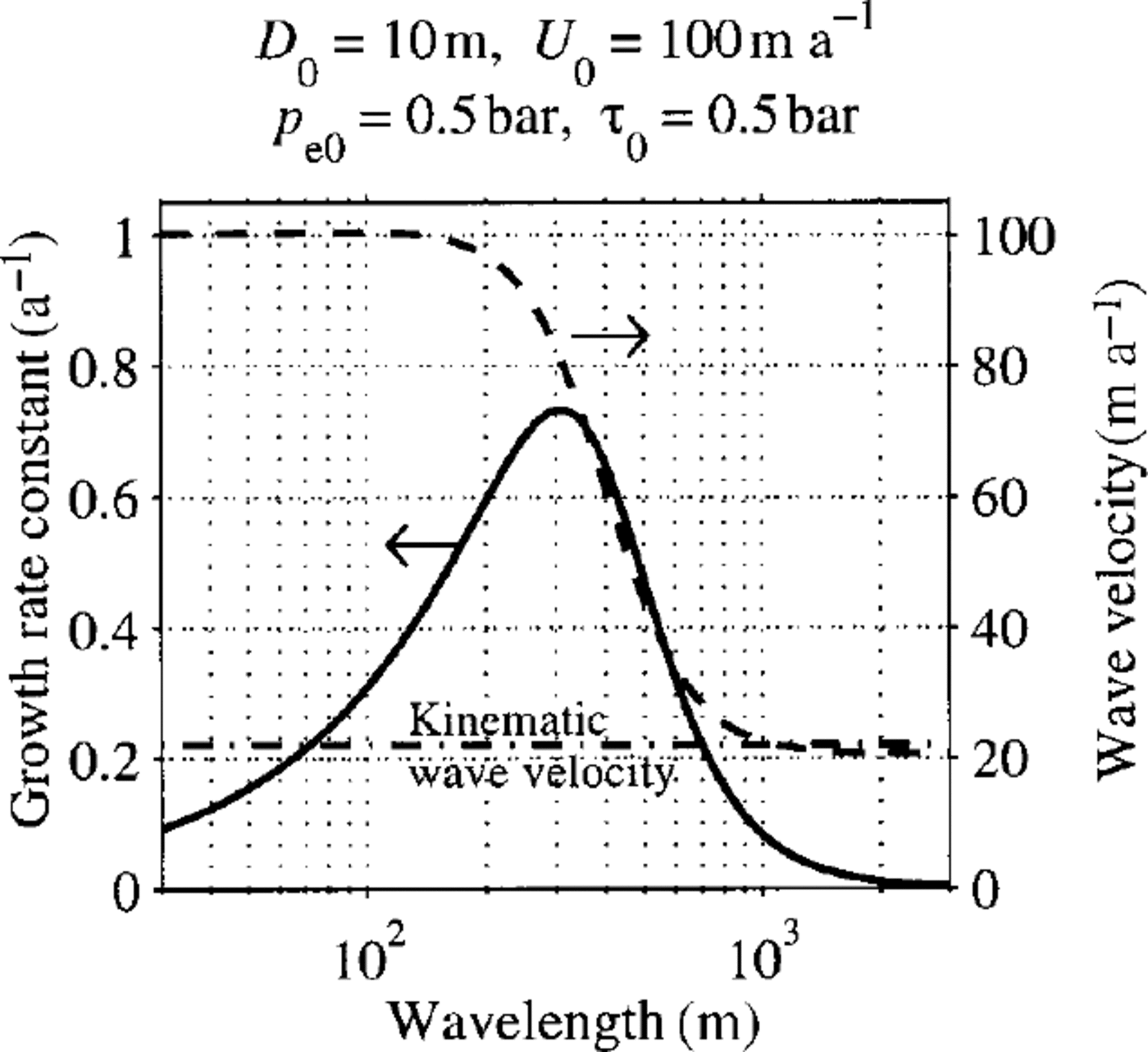
Here we look in detail at how variations in the field variables (tractions, velocities, etc.) give rise to the conditionally stable evolution of variations in till forms. A till bump alters its physical environment. At short wavelength, its presence sets up new stresses within the ice, in particular longitudinal stresses, which cause the tangential and normal traction (forces per unit area) exerted by the flowing ice on the till to change. Increased normal traction increases the effective pressure, which increases intergranular friction within the sediment and makes it stiffer. Increased shear stress causes increased flow. An increased till thickness causes an increased interfacial effective pressure owing to the density difference between ice and water (Reference HindmarshHindmarsh, 1996; Reference Hindmarsh1998a), affecting the normal force on the till. All these effects combine to alter the till-flux distribution and thus the till-profile evolution, which is reflected in the till-amplitude growth rate and wave velocity of the till (Fig. 2). This shows that, for the prescribed model constants, there is a maximum growth rate at about 300 m; it is suspected that drumlins become dragged out to create the lineations with long axes much greater than 300 m. This maximum can be readily altered by modifying the parameters. At shorter wavelengths, growth rates become smaller with till waves moving at the ice velocity; while at long wavelengths, till waves move at the kinematic wave velocity. One can distinguish between: flow which is coupled, where the presence of the ice significantly modu-lates the flow of the till; and uncoupled cases, where the presence of the ice does not affect the flow of the till and its evolution is restricted to the translation of a neutrally stable kinematic wave.
Illustrating the dependence of growth-rate constant (solid) and wave velocity (dashed) on wavelength.
Two cases are illustrated in Figure 3, an unstable one, L = 300 m and a marginally stable one with L = 3000 m. The most significant feature is manifested in the three graphs comprising the right-hand column of the figures. They show the contribution to the velocity and the flux arising from variations in the tangential traction, the normal traction and hydrostatic effects (stemming from till-thickness changes) on the interfacial effective pressure. For the unstable case, the contributions from the viscous tractions are larger than the contributions from the hydrostatic variations in the interfacial effective pressure. These are of opposite sign, and the total flux is therefore somewhat less in magnitude than the contributing parts. For the stable (long-wavelength) case, the viscous tractions are weak. The main contribution comes from hydrostatic variations in the effective pressure; the ice and till flows are almost uncoupled. Comparison of the stable and unstable cases shows markedly different traction phasings. Classical NK theory explains why the viscous tractions decrease with wavelength between 300 m and 3000 m; as wavelength decreases, the ice is “seen” as more viscous by the till and the coupling becomes tighter. Note that drumlin growth-rate constants are very high, often around 1a1, which means that they form very fast indeed (Fig. 2).
Illustrating the role of viscous forces in shaping drumlins at a wavelength of 300 m (upper diagrams) and 3000 m (lower diagrams). The left-hand figures show thickness (D
1), thickness evolution (δD
1/δt), viscous tangential
 and normal
 tractions, while the right-hand figured show normalized flux contributions from variations in the tangential traction
 normal traction
 and till thickness
 , as well as the total contribution (q
1). Units are arbitrary, but consistent for dimensionally equivalent variables.

At long wavelength, the presence of the bump affects the stress distribution within the ice, but in rather different ways from the processes occurring at short wavelength. Under the hydraulic assumptions used here (see Reference HindmarshHindmarsh, 1998c for a detailed discussion), interfacial effective pressure is taken to be constant. Additional stresses arise from the fact that the presence of the bump disturbs the ice-surface geometry, which in turns affects the basal shear stress and thus the flow of the till. We anticipate from the marginal stability that static effects are stronger than shear-stress effects and a detailed examination of the stress distributions (not shown in this paper) shows this to be true. In other words, at these long wavelengths coupling is weak and the till waves behave very much as the uncoupled, neutrally stable, kinematic waves described above.
4. Searches Over Parameter Space
Previous studies and the present study show that whether stability occurs or not depends on many parameters, some of which are unknown but likely to remain fixed during the evolution of an ice stream (e.g. the rheological indices a, b) and others which are likely to be highly dynamic. Hence, it is important to explore the question of stability over all the parameters, sampling at a sufficiently high density to obtain the broad patterns. In this section, we report the results of searches over parameter space for the short- and long-wave- length cases. Parameter space is a multi-dimensional space whose axes are the parameters under consideration. In both cases of the wavelength, the parameter space is described and the proportion of cases where modes are unstable (i.e. relief is growing) are discussed.“Mode” is a concept from linear theory, which finds that an evolving field, when considered at a particular wavelength, has a growth/decay time constant and a wave velocity. The short-wavelength solution has one mode for a given wavelength which corresponds to the till growth rate and travelling-wave velocity, while the long-wavelength solution has two modes which are each combinations of ice and till relief, corresponding to different growth rates and wave velocities. It is known (Reference HindmarshHindmarsh, 1998c) that one of these two modes is very strongly diffusive and corresponds very closely to the ice-surface diffusion mode discussed by Reference NyeNye (1959). The other mode is the one that is potentially unstable (Reference HindmarshHindmarsh, 1998c; Reference FowlerFowler, in press); this mode has expressions in both ice and till surface relief.
We also consider bed-erosion modes. It is assumed in this paper that changes in bedrock shape resulting from abrasion occur much slower than do changes in the till or ice thickness. In order to compute abrasion, we first compute steady ice/till configuration and check its stability. I fit is stable, the till distribution can persist, meaning that the abrasion distribution can also persist and thus we can address the issue of whether bedrock relief grows. If the till distribution is unstable, we cannot predict the ultimate till-thickness distribution with the present model, so the sample point is discarded.
Previous studies have shown that whether instability occurs or not depends in a complex way on the location of the sample point in a parameter space defined by subglacial physical quantities such as the stress, the effective pressure, etc. Since we do not understand ice-sheet glaciology well enough to predict these quantities, and, moreover, we suspect that the physical environment is highly variable, we need to explore the parameter space in order to determine whether a reasonable proportion of sample points is unstable. If it were not, we would have to conclude that our mechanism was unlikely to be the sole cause, or that the system operated so as to restrict itself to areas in parameter space which were unstable. It turns out that substantial areas of parameter space are unstable, a desirable result.
For the short-wavelength case (Nye—Kamb solution), the parameter-space sample points are the direct product of the sets comprising the direct product of the following seven
dimensional parameter space:

Thus, at each of these points, stability was assessed and the growth rate computed. These computations were carried out for various distributions of the velocity between till—bed sliding, till internal deformation, and ice—till sliding. Four cases were considered with the velocity apportioned respectively as follows (a) (0, I, 0), (b) (0, 0.5, 0.5), (c) (I, 0, 0) and (d) (0.333, 0.333, 0.333). In addition, a case with no till present was computed to determine the abrasion characteristics under these conditions. Note how the wavelength is a parameter; this means that we are considering sinusoidal beds of the corresponding wavelength.
Results are presented in Figure 4 (proportion of sample points with unstable till-sheet flow) and in Figure 5 (proportion of sample points with glacial abrasion causing accentuation of relief). For each parameter, results are binned across all the remaining parameters. For example, for Ub — 100 m a-1, the results for

are considered as a set, and the proportion with unstable till- sheet flow or growing bedrock relief is computed. This is plotted in Figures 4 and 5. Where motion was by till—bed slip alone, all cases were stable. Figure 4 shows that ice—till slip affects the proportion of unstable modes but still leaves a substantial number of unstable modes. These diagrams show that the dependence of the stability system on its position in parameter space is very complicated; one reason for this must be the interplay between viscous and static forces discussed in the last section. Also plotted in Equation (4) are proportions greater than growth rates of 1 a-1 and 10 a-1, indicating that a good proportion of drumlins can grow very fast indeed.
Nye—Kamb configuration (short wavelength): Proportion of positive (unstable) growth rates of till-sheet modes binned against each parameter. Horizontal axis is the parameter, vertical axis is the proportion. Cases are: (a) all till internal deformation; (b) ice basal-velocity, due half to internal deformation and half to ice—till slip; and (c) ice basal-velocity due equally to till—bed slip, till internal deformation and ice—till slip. Also shown are proportions of cases with growth rates greater than 1a—1 (dash—dot) and 10a—1 (dotted). The parameters are: T 0, shear stress; p e0, effective pressure; D 0, till thickness; L, till—bedrock perturbation wavelength; U b, ice basal-velocity; a, shear-stress index in flow/sliding laws; and b, negative of effective pressure index in flow/sliding laws.

Nye-Kamb configuration (short wavelength): Proportion of bedrock modes growing under abrasion binned against each parameter. Horizontal axis is the parameter, vertical axis is the proportion. Cases are: (a) all till-bed slip; and (b) ice basal-velocity due equally to till-bed slip, till internal deformation and ice-till slip. Also shown are proportions with growth rate of 1 (dash-dot). See caption for Figure 4 for meaning of symbols.
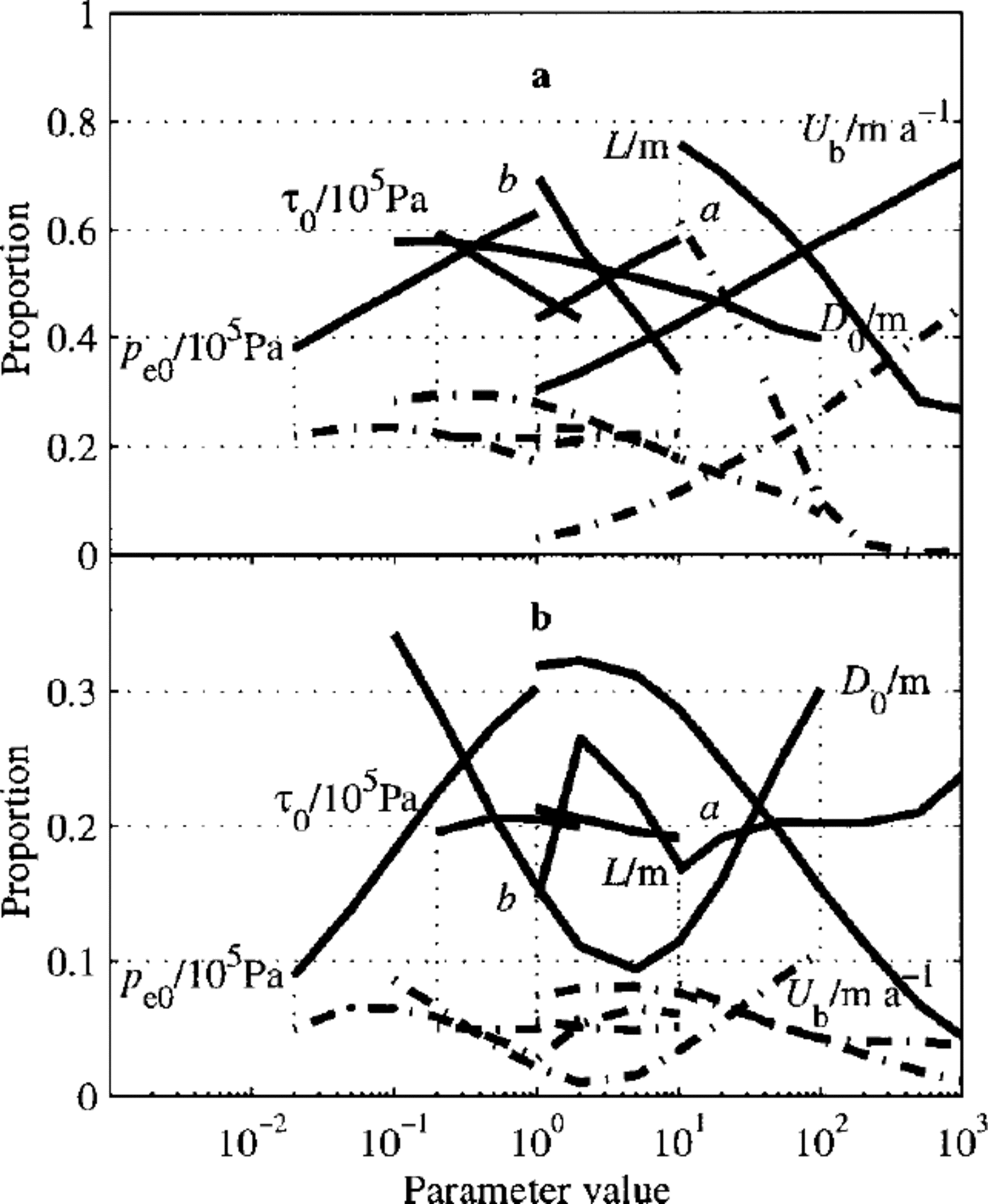
Figure 5 shows the proportion of bedrock modes that leads, by abrasion, to amplification of these modes. (How erosion is incorporated is discussed in the Appendix). A sine-wave perturbation is introduced into the bedrock and the steady till profile computed. If this steady till profile is stable, the profiles are used to compute the abrasion rate of the sine wave in the bedrock, and in particular, whether it is shrinking or growing. (If the till profile is unstable, then the till cover will evolve and we cannot, with the linear theory, compute the abrasion rate) The surprising result of this is that the proportion of bedrock modes that become amplified is greater when there is contribution to the ice basal motion from internal deformation and ice—till slip. However, since velocities at the till—bed interface are lower when there is a contribution from other basal mechanisms, we do not expect the rate of erosion rate to be as great. Also plotted in Equation 4 are proportions greater than growth rates of 1m m 1; in other words those forms that for a metre bump grow at the rate of > 1m m 1, eroded by the background (zeroth-order) process. This is clearly not a physically conceivable situation (as it implies negative abrasion) and has in fact violated the linearity condition, but it does indicate that whalebacks can induce the severe variations in abrasion needed to shape whalebacks. A smaller bump would reduce the growth rate and the linearity condition would not be violated.
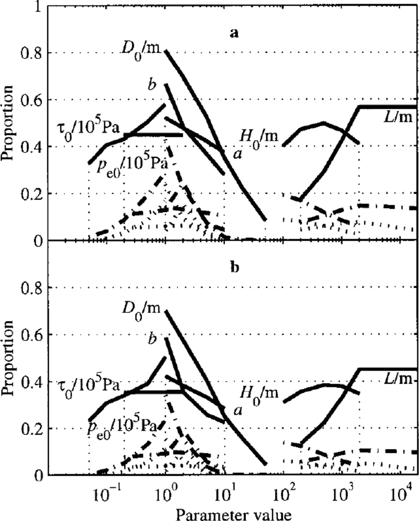
We now consider long wavelength perturbations, where mechanics are described by the shallow ice approximation. Parameter space for the coupled ice—till system has been explored by sampling at approximately 60 000 points. The set of sample points comprised the direct product of the sets

where L = 2π/k. Excluded are the points in parameter space where L ≤ H 0, as the shallow ice approximation is not valid here. The basal velocity was set at 100 m a-1, by adjusting the rate factor: in this case it can be deduced from the equations that the basal velocity does not affect the proportion of modes that are unstable (Reference HindmarshHindmarsh, 1998c). This study was carried out for the same combinations of TBS, TID and ITS as for the NK configuration. Where there is TBS, only a very small proportion (<1%) of unstable cases was found. For the cases where there was no TBS, Figure 6 shows the proportion of cases with positive growth rate of till-sheet modes, binning along each parameter in turn. These cases show very strong dependencies on the thickness and the effective pressure index b. The system is most unstable for rather thin tills, which are least likely to develop into a surface of large till relief. Also shown is the proportion with growth rates higher than 0.01 a—1 and 0.1 a—1. There are a few cases with growth rates large enough to be of practical significance, so some long-wavelength drumlins may form through long-wavelength coupling. Including ice—till slip reduces the proportion of unstable modes by a relatively small amount. The proportion of bedrock relief modes that is unstable under abrasion is nearly zero (not shown). This lends support to Reference OerlemansOerlemans’ (1985) non-linear long-wavelength mechanism, rather than Reference MazoMazo’s (1989) infinite-plane model.
Flow down an infinite plane, long-wavelength features, proportion of positive (unstable) growth rates of till-sheet modes binned against each parameter. Horizontal axis is the parameter, vertical axis is the proportion. Cases are: (a) all till internal deformation; and (b) ice basal-velocity, due half to internal deformation and half to ice-till slip. Also shown are proportions with growth rates > 0.01 a— 1 (dash-dot) and proportion with growth rates >0.1 a— 1 (dotted lines). See caption for Figure 4 for meaning of symbols.
5. Drumlin and Whaleback Seeding as a Fluid-Dynamical Instability
The idea that drumlin seeding might be a fluid-dynamical instability dates back in its modern form to Reference Smalley and UnwinSmalley and Unwin (1968), who introduced the idea of a stability parameter which varied in space, represented by a in Figure 7a. This stability parameter would be a descriptor of the subglacial physical environment, for example the effective pressure. Where it exceeded a critical value, drumlins might, for example, form; where the stability parameter was less than the critical parameter, drumlins would not form. This is quite a fundamental dynamical concept, and any analysis that yields conditional stability of drumlins will likely yield a Smalley—Unwin bifurcation pattern, i.e. one where stability varies in space. However, models of till as a viscous fluid where till mass-conservation plays a fundamental role (Reference Boulton, Menzies and RoseBoulton, 1987) are, from a point of view of physical mechanisms, somewhat different from the mechanisms proposed by Smalley and Unwin.
Illustrating generalization of the Smalley—Unwin bifurcation. In the upper figure, the bifurcation parameter is a, and drumlins form where this exceeds a critical value. In the lower figure, the drumlin formation condition is for both parameters to exceed a critical value; drumlin size is affected by the second parameter varying in space. The two axes thus represent horizontal and vertical co-ordinates.

Smalley and Unwin did not explicitly address the question of the size or the spacing of the drumlins. The theory outlined in this paper has only one horizontal dimension, and the horizontal length scale in this linearized theory has to represent both the drumlin size and the spacing. A true non-linear calculation will address these related, but nonetheless distinct, issues. Moreover, numerical experiments with pre-existent relief show that the action of ice—till coupling is to extend drumlins in the direction of flow, which is widely believed to happen (Reference ClarkClark, 1993). It is thus not clear whether the longitudinal dimension of a drumlin represents the initiation length-scale. Nor is it clear whether the plan—aspect ratio of the drumlin, when it originally formed, was around unity or not.
Nevertheless, we can generalize the Smalley—Unwin ideas by using the concept that drumlin size/spacing will be initiated at the fastest-growing wavelength. The results presented in this study show that the fastest-growing wavelength is a function of the physical environment at the base of the glacier, so our first generalization is in Figure 7b, which shows a slow variation in drumlin size across the drumlin fields. This is ascribed to a slow change in a second parameter, which causes the dominant wavelength to change and drumlin size to change. There is nothing in the theory to suggest that, as the separatrix between stable and unstable is reached, drumlin wavelength becomes infinitely small (and thus invisible) or infinitely large (and thus no longer a drumlin); what actually happens is that as the stability parameter is passed, the range of wavelengths for which instability occurs increases, and the growth rate of relief also increases.
Similar ideas relate to the formation of whalebacks, which are convex forms in bedrock of glaciogenic origin (Reference EvansEvans, 1996). In this work, they are assumed to be caused by an instability; the coupling between the bedrock form and the ice flow modifies the abrasion pattern so as to cause the relief to grow. Again, areas where this instability operates depend on the subglacial physical environment and, again, we can expect there to be preferred wavelengths. However, the rate of growth depends upon the rate of erosion by the glacier; typical erosion rates of 1 mm a 1 mean that several thousand years would be needed to abrade even a small whaleback form.
6. Concluding Remarks
These studies show that the physically based model of till flow developed in the 1980s by Reference AlleyAlley (1989), Reference Boulton, Menzies and RoseBoulton and Hindmarsh (1987) and Reference ClarkeClarke (1987) has the potential to explain drumlin formation under more general conditions than those considered by Reference HindmarshHindmarsh (1998b, Reference Hindmarshc), as well as, in common with some other models, the ability to explain the development of bedrock relief. This paper has extended the studies of Reference HindmarshHindmarsh (1998b, Reference Hindmarshc) by considering the effect of interfacial slip on the dynamics of coupled flows of ice and till. In most of the cases, the proportion of unstable modes is not so high as to suggest that drumlins should be ubiquitous (which they are not); any model should be able to explain their absence as well. The model may over predict whaleback formation, but they require a substantial amount of erosion to form and may thus only be created where significant erosion has occurred.
We thus postulate the following model of drumlin-field development. Since growth rates are high when velocities are high, drumlins can form in very short time periods, centuries or even decades, reflecting flow directions over short time periods. Changes in physical conditions will alter the most unstable wavelength and this will result in the phenomenon of two different superimposed drumlin populations, which is a transient phase.
Acknowledgements
I had significant conversations with G. S. Boulton, M. DuBois, C. D. Clark, I. S. Evans and A. C. Fowler. F. .S. L. Ng’s review was much appreciated.
Appendix A. Nye—Kamb Solution And Bedrock Perturbation
In this appendix we show how Hindmarsh’s (1998b) extended Nye—Kamb solution can be expanded to include bedrock topography. The linearized ice basal-velocity relationship (cf. Equation (5)) is now

while the kinematic condition incorporates the fact that bedrock topography adds to the ice—till interface topography. This is the main difference between this case and the case with flat bedrock. Thus,

We get the same lefthand side as in Equation (4), but with the righthand side given by

The interfacial tractions are now given by

(cf. Equation (11)) and the till thickness evolution equation is now

A steady-state is obtained when the till thickness, represented by D c, solves
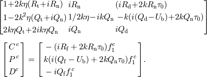
This has been obtained by combining Equations (4), (12) and (14) and applying the condition 
Appendix B. Abrasion
The postulated abrasion law is of the form

where e is the erosion rate (positive for a lowering of the surface) and a is a phenomenological constant. The erosion perturbation is given by

In the Nye—Kamb solution, the basal-boundary conditions require computation of the interfacial tractions. Substitution of Equation (13) into the Fourier transform of Equation (15) yields an equation for e
c, the Fourier coefficient of e
1 . Here a positive value indicates erosion (damping) of the mode, i.e. 
We now consider abrasion under the shallow-ice approximation. The fields are given by

whence from Equation (7)