


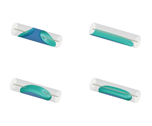

1. Introduction
Capillary occlusion occurring mainly due to the effect of surface tension is a common phenomenon in small tubes (de Gennes, Brochard-Wyart & Quéré Reference De Gennes, Brochard-Wyart and Quéré2004; Zhang, Yang & Wang Reference Zhang, Yang and Wang2006; Mirski et al Reference Mirski, Lele, Fitzsimmons and Toung2007; Cheah, Kevrekidis & Benziger Reference Cheah, Kevrekidis and Benziger2013; Kim et al Reference Kim, Baskota, Kang and Jung2023). A small but sufficient amount of liquid may occlude a capillary or adhere to part of the wall of a capillary. On some occasions, capillary occlusion should be avoided or removed to ensure or enhance the flow performance in containers/tubes. It is necessary to investigate the non-existence and existence conditions, and the stable states of capillary occlusion.
For a droplet in a capillary, there are multiple equilibrium configurations under different conditions and the change between two of the multiple equilibrium configurations can occur by changing the conditions. Slobozhanin, Alexander & Fedoseyev (Reference Slobozhanin, Alexander and Fedoseyev1999) theoretically studied the shape and stability of equilibrium configurations with both contact lines on the lateral wall of a cylinder under zero gravity, and found three equilibrium configurations, i.e. a droplet, a liquid ring and a liquid bridge, dependent on the droplet volume and contact angle. Lubarda (Reference Lubarda2015) theoretically investigated the stability of a cylindrical liquid bridge in different types of unduloidal equilibrium configurations and found that for a given volume of the liquid and specified height of the bridge, the lateral surface of a uniform cylindrical bridge is smaller than the surface area of any unduloidal equilibrium shape. Hallaby & Kizito (Reference Hallaby and Kizito2016) carried out experimental and simulation research on the dynamics of plug formation in a circular cylinder under low-Bond-number conditions. They found that with the volume of the injected liquid increasing to a large enough value, a transition of the droplet shape from a liquid annulus to a liquid bridge occurs. Vogel (Reference Vogel2019) theoretically observed two types of surfaces with these properties in circular cylinders are Delaunay surfaces (toroidal drops are bounded by them) and cylinders (i.e. the free surface of the liquid is another circular cylinder) in the absence of gravity. Hu, Romanò & Grotberg (Reference Hu, Romanò and Grotberg2023) developed the entropic lattice Boltzmann model to investigate the surface tension effects on liquid plug rupture in two- and three-dimensional channels.
Different from the equilibrium configurations occurring under different conditions, bistability of a droplet in a capillary tube under the same conditions at zero-gravity has been reported by several studies in the situation of zero gravity. Lv & Hardt (Reference Lv and Hardt2021) theoretically studied the wetting of a liquid ring with a small volume in a capillary tube without considering the effect of gravity and found stable droplet configurations including a liquid ring, a droplet attached at a side and a liquid plug. The tristability (in any one of the three configurations) can occur. Pour & Thiessen (Reference Pour and Thiessen2019) theoretically observed that the bistability in either the occluding configuration or the non-occluding bridging configuration (defined as the gas–liquid interface in the middle cross-section of a droplet meeting both the outer wall and the inner wall) appears for a sufficiently large amount of liquid in an eccentric annular capillary tube under zero gravity. The occurring condition of the bistability changes with the contact angle, the inner-to-outer radius ratio and eccentricity. The occurrence of the multistability under zero gravity can be attributed to a small volume of droplet (Lv & Hardt Reference Lv and Hardt2021) or the combination of the annulus shape and the eccentricity of the annulus (Pour & Thiessen Reference Pour and Thiessen2019) (the combination leads to the possibility of non-occluding bridging configuration while under zero gravity, either a concentric annulus shape or an eccentric non-annular cross-section does not result in the existence of the bridging configuration).
A transverse body force can lead to rich physical phenomena of the gas–liquid interface in a capillary (e.g. Manning, Collicott & Finn Reference Manning, Collicott and Finn2011). For a very large amount of liquid in a capillary, the critical Bond number (measuring the gravitational force relative to the surface tension force) of liquid non-occlusion was first determined for a circular capillary tube (Manning et al Reference Manning, Collicott and Finn2011). Subsequently, the critical Bond numbers of liquid non-occlusion in capillary tubes of other cross-sections under transverse body forces were studied (e.g. Parry et al Reference Parry, Rascón, Jamie and Aarts2012; Rascón, Parry & Aarts Reference Rascón, Parry and Aarts2016; Zhu, Zhou & Zhang Reference Zhu, Zhou and Zhang2020). Tan et al (Reference Tan, Zhou, Zhang, Zhu and Fu2022) observed an interesting re-entrant transition between capillary non-occlusion and plug in an eccentric annular capillary tube in a transverse body force field in a two-parameter space (γ, Bo), with γ and Bo being the contact angle and Bond number, when Bo gradually changes between zero and a large enough value at a contact angle. The occurrence of the re-entrant liquid state transition is attributed to the shape of eccentric annulus and the transverse body force both of which can cause liquid non-occlusion.
In addition to a common small circular tube, a small annular tube is an interesting tube with rich physical phenomena due to the presence of inner and outer walls. The gas–liquid interface in an annular tube has been widely studied. Elcrat, Kim & Treinen (Reference Elcrat, Kim and Treinen2004) theoretically studied the meniscus in a symmetric concentric annular capillary tube with axial gravitational acceleration, where the contact angles on the inner and outer walls can be different. Gordon & Siegel (Reference Gordon and Siegel2010a,Reference Gordon and Siegelb) theoretically approximated the concentric annular capillary surfaces with equal contact angles in a gravity field along a radius. Based on the theoretical research on the critical liquid non-occlusion condition in a transverse gravity field, Zhou et al (Reference Zhou, Zhang, Zhu, Tan and Fu2021) found that a concentric annular capillary is preferable to a circular capillary in view of liquid non-occlusion. It was theoretically observed that eccentricity can be employed to avoid liquid occlusion in an annular capillary at zero Bond number (Smedley Reference Smedley1990; Pour & Thiessen Reference Pour and Thiessen2019) or under transverse body forces (Tan et al Reference Tan, Zhou, Zhang, Zhu and Fu2022). The majority of the above studies are based on an infinite or very large volume of liquid. Whether the multistability of a sufficient amount of liquid can occur in a circular or annular capillary tube in a transverse body force field is interesting and worthy of investigation, but remains unknown to date.
In the above situation, we theoretically investigate the stable equilibria of a droplet, which has a finite but sufficient volume to form a liquid column in a circular or annular tube. In addition, we also use Surface Evolver (Brakke Reference Brakke1992) to numerically compute the shape of a droplet in equilibrium state. Interestingly, bistability in a circular capillary and tristability in a concentric annular capillary (the concentric annulus can lead to the existence of bridging configuration, similar to Pour & Thiessen Reference Pour and Thiessen2019) are observed in a transverse body force field. Furthermore, the combination of the annulus effect and the transverse body force effect can increase considerably the complexity of the liquid states.
In this paper, the multistability of a droplet with a finite but sufficient volume in a circular or annular concentric capillary is theoretically investigated. The eccentricity effect of the annulus is not thus considered here to clearly illustrate the combination of the two effects on the multistability of liquid. This paper is organized as follows. In § 2, a mathematical model is developed to calculate the non-occluding interface, and the condition for existence of the occluding interface is also given. Different stable states can be predicted and the critical occurring conditions of theirs can then be determined. In § 3, the multistability of a droplet in a circular or annular capillary is studied, the effects of Bond number, contact angle and radius ratio are examined, and the critical occurring conditions of multistability are analysed. In § 4, the conclusions drawn are presented.
2. Mathematical model
In a right capillary filled with two immiscible fluids (a liquid and a gas), different liquid states can be observed including liquid non-occlusion and liquid occlusion. We consider the volume of liquid large enough to form a liquid column (i.e. a sufficiently long and continuous droplet) and investigate the liquid states. In § 2.1, a mathematical model under an invariant cross-section assumption is proposed to determine the shape of the stable non-occluding interface. Furthermore, in § 2.2, the limitation of the invariant cross-section assumption is discussed and the compensation for the mathematical model is provided. Additionally, in § 2.3, the condition for the existence of an occluding interface is given.
2.1. Calculation of 2-D non-occluding interface
For a liquid column with a non-occluding configuration, the cross-sectional shape can be assumed to be invariant along the axis direction of the tube, except for the segments near the two ends. Then the total free energy is approximately obtained as the product of the length of the liquid column and the energy of a general cross-section. By determining the liquid cross-section which minimizes the total free energy, we can obtain the non-occluding liquid column reaching stable equilibrium. Therefore, the three-dimensional (3-D) problem about the stable equilibrium of a non-occluding droplet is reduced to a two-dimensional (2-D) problem. This approach was applied to obtain the equilibrium capillary bridge between the parallel cylinders (Princen Reference Princen1970) and that in the eccentric annular tube (Pour & Thiessen Reference Pour and Thiessen2019); however, the transverse body force was neglected in the two studies.
Figure 1 shows the schematic of a gas–liquid interface in a general cross-section of a long open circular capillary tube of radius R, or a long concentric annular capillary tube of inner radius Ri and outer radius R in the presence of a transverse gravity field in Cartesian coordinates (x, y, z). The case of a circular capillary can be seen as a special case of a concentric annular capillary with the inner radius of 0. The inner-to-outer radius ratio of the concentric annular tube is defined as χ = Ri/R. The origin of the Cartesian coordinates lies at the centre of the circle(s).
Schematic of general cross-section of a liquid column partially filling (a) an open circular capillary tube of radius R or (b) a concentric annular capillary tube of outer radius R and inner radius Ri in a transverse gravity field. The gas–liquid interface  $\varGamma$ intersects the circle(s) at contact points with the contact angles γ. Here,
 $\varOmega$ is the total area of the gap between the total inner and outer perimeters
 $\varSigma_i $ and
 $\varSigma_o $. Additionally,
 $\varOmega$* is the area of the liquid wetting the inner and outer perimeters
 $\varSigma_i^\ast $ and
 $\varSigma_o^\ast $. When Ri = 0, the concentric annulus is changed to the circle. Due to the symmetry of the cross-section, only the interface in the negative-x half-plane is calculated, and the numerics 1 and 2 denote left and right boundary points of the calculated half-interface, respectively. Additionally, α and β are the orientation angles of contact points on the outer and inner wall, measured counterclockwise, starting from the positive y axis, and α, β ∈ [0, π].

The forces of the liquid in a capillary tube are the capillary force due to the surface tension and the transverse gravity. The Bond number, which is used to characterize the relative strength of gravity to the capillary force, is defined for a circular tube or a concentric annular tube as
 \begin{equation}Bo = {R^2}/l_{ca}^2,\end{equation}
where the capillary length lca is given by  ${l_{ca}} = \sqrt {\sigma /\rho g} $, where σ is the surface tension between liquid and gas, ρ the density difference (positive) between liquid and gas, and g the gravitational acceleration.
The non-occluding droplet with an invariant cross-section along the tube axis has the relationship
 \begin{equation}L = V/|{{\varOmega ^\ast }} |,\end{equation}
where L, V and  ${\varOmega ^\ast }$ are the length, the volume and the cross-section area of the liquid, respectively. The total free energy of a 3-D non-occluding droplet in a capillary tube, which contains the free surface energy, the wetting energy and the gravitational energy, is expressed as
 \begin{align}E &= \sigma L|\varGamma |-
\sigma L|{{\varSigma ^\ast }} |\,\textrm{cos}\,\gamma + \sigma
Ll_{ca}^{ - 2}\int_{{\varOmega ^\ast }}
{y\,\textrm{d}\kern0.07em x\,\textrm{d}y}\nonumber\\
&= \left( {\frac{{|\varGamma |-
|{{\varSigma ^\ast }} |\,\textrm{cos}\,\gamma + l_{ca}^{ -
2}\int_{{\varOmega ^\ast }} {y\,\textrm{d}\kern0.07em x\,\textrm{d}y}
}}{{|{{\varOmega ^\ast }} |}}} \right)\sigma
V,\end{align}
where  $\varGamma$ is the gas–liquid interface,
 ${\varSigma ^\ast }$ is the wetting perimeter and γ is the contact angle. For the case of concentric annular capillary tube, the total length of wetting perimeter is given by
 \begin{equation}|{{\varSigma ^\ast }} |= |{\varSigma _i^\ast } |+ |{\varSigma _o^\ast } |,\end{equation}
where  $\varSigma _i^\ast $ and
 $\varSigma _o^\ast $ are the wetting inner and outer perimeters, respectively (see figure 1b). Regarding the minimizing problem on the total free energy (2.3), for a specific liquid with a sufficiently large and fixed volume (i.e. the values of σ and V in (2.3) are constant), we only need to consider
 \begin{equation}\varPhi = \frac{{|\varGamma |- |{{\varSigma ^\ast }} |\,\textrm{cos}\,\gamma + l_{ca}^{ - 2}\int_{{\varOmega ^\ast }} {y\,\textrm{d}\kern0.07em x\,\textrm{d}y} }}{{|{{\varOmega ^\ast }} |}}.\end{equation}
Note that (2.5) represents the total energy of a non-occluding droplet but only relates to the 2-D arguments in the cross-section, so that the minimization on the total energy of a droplet is reduced to a 2-D problem.
The 2-D gas–liquid interface in the cross-section is described by the boundary value problem (BVP) consisting of the Young–Laplace equation and the boundary conditions. Due to the symmetry of the cross-section about the vertical line of symmetry, as shown in figure 1, only the interface in the negative-x half-plane is calculated to save computational time. Here, we use the Young–Laplace equation in two dimensions in the parametrization form by the arclength s (Finn Reference Finn1986; Bhatnagar & Finn Reference Bhatnagar and Finn2016):
 \begin{equation}\frac{{\textrm{d}\kern0.07em x}}{{\textrm{d}s}} = \textrm{cos}\,\psi ,\quad \frac{{\textrm{d}y}}{{\textrm{d}s}} = \textrm{sin}\,\psi ,\quad \frac{{\textrm{d}\psi }}{{\textrm{d}s}} = l_{ca}^{ - 2}y + \lambda ,\end{equation}
where ψ is the angle between the interface and the horizontal direction, and λ is a Lagrange multiplier arising from the volume constraint of the liquid. Considering the free contact point, the conditions for the left and right boundary points of the interface curve in the negative-x half-plane can be respectively given by
 \begin{gather}{\psi _1} = \alpha + \gamma + {\rm \pi}+ 2N{\rm \pi} ,\end{gather}
 \begin{gather}{\psi _2} = \frac{{\rm \pi} }{2} + 2M{\rm \pi} \quad \textrm{or}\quad {\psi _2} = \beta - \gamma + 2M{\rm \pi} ,\end{gather}
where the subscripts 1 and 2 denote the left and right boundary points of the interface, and N and M are arbitrary integers. According to the different non-occluding configurations, (2.8a) or (2.8b) is applied to the right boundary point. In the case of circular capillary, the only 2-D non-occluding configuration is the liquid located on the bottom of the cross-section (see figure 1a). In the case of concentric annular capillary, there may exist two types of 2-D non-occluding configurations, i.e. non-bridging configuration (the interface stays above or under the inner circle) and bridging configuration (see figure 1b). For the configuration in the circular tube or the non-bridging configuration in the concentric tube, the right boundary point of the interface is on the symmetrical line and corresponds to condition (2.8a). However, for the bridging configuration in the concentric tube, the right boundary point is a gas–liquid–solid contact point on the inner perimeter and corresponds to condition (2.8b). In all cases, the left boundary point is a contact point on the outer perimeter, and thus condition (2.7) is applied.
To obtain the 2-D gas–liquid interface with a specific configuration, a shooting method is applied to solve the BVP from (2.6) to (2.8). We take a given point on the outer perimeter of the tube as the initial point for the calculation on the interface. According to the contact angle γ and (2.7), we can get a set of initial value (x 1, y 1, ψ 1). Since the Lagrange multiplier λ is unknown, we first guess a value for λ. Then, the interface given by the Young–Laplace equation (2.6) is calculated from the initial point through a forward Euler method, and the calculation ends when the interface reaches the right boundary. It is checked whether the right boundary condition (2.8) is satisfied. If not, the value of λ is changed and the calculation on (2.6) is repeated. The bisection method is used for searching the correct value of λ that satisfies (2.8). Once the correct λ is determined, the interface can be obtained. Notably, the Lagrange multiplier λ here is a pending parameter depending on the shape of the non-occluding interface and the boundary conditions. This is very different from the occluding case, in which the corresponding Lagrange multiplier λP is constant for a given tube cross-section and contact angle (see (A4) in Appendix A).
The corresponding energy (2.5) can be calculated after obtaining the 2-D gas–liquid interface in the cross-section. For a specific liquid configuration, we aim at searching the interface which reaches a local minimum energy. The energy minimizing procedure is performed as follows: (1) treat the position of the contact point on the outer perimeter (i.e. the value of α) as the independent variable; (2) calculate the 2-D gas–liquid interface by solving the BVP from (2.6) to (2.8) for a specific 2-D non-occluding configuration; (3) calculate the value of  $\varPhi$ corresponding to the interface by (2.5); (4) vary the position of the left contact point along the left half of the outer perimeter (from α = 0° to α = 180°) to find the local minimum
 $\varPhi$min for a specific 2-D liquid configuration. For simplicity, both the radius of the open circular capillary tube and the outer radius of the concentric annular capillary tubes are set as 1 in computations. In the case of concentric annular capillary, this procedure will be performed separately for the non-bridging configuration and the bridging configuration.
Through the above procedure, the shape of the 2-D liquid configuration can be determined, allowing the energy to reach the local minimum  $\varPhi$min. As a result, the non-occluding liquid column with the corresponding invariant cross-section is expected to be stable to the planar perturbations which are the most dangerous to the liquid column with an infinite liquid volume in a tube (Myshkis et al Reference Myshkis, Babskii, Kopachevskii, Slobozhanin, Tyuptsov and Wadhwa1987). The stability can also be determined by solving the associated eigenvalue problem for the second variation of the energy functional (see Appendix B). The smallest eigenvalue is found to be positive for any non-occluding interface determined by the above energy minimizing procedure, which validates the stability.
The theoretical model proposed in this section essentially requires the droplet to be infinitely long to precisely fulfil an invariant cross-section of liquid. We compare the theoretical results with the results of droplets of finite but sufficiently large length calculated using the Surface Evolver (SE) for various cases, as depicted in figure 2. In addition to examining the cross-sectional shape of the liquid, the Lagrange multiplier λ in the Young–Laplace equation (2.6) is taken as another validating parameter, because it is crucial in calculating the interface during our numerical process and is easily accessible in the SE program (Brakke Reference Brakke2013). The SE settings can be seen in Appendix C. The theoretical results show good agreement with the SE results in terms of the cross-sectional shape and the value of λ, as shown in figure 2. In SE modelling, we set a very large liquid volume (the volume is 20 and the radius of the outer wall is unit length), which ensures the formation of sufficiently long droplets in all configurations. If the volume is set to a small value (empirically, such as a value less than 8 for the cases γ = 165° shown in figure 2), the SE results will deviate significantly from the theoretical results. Furthermore, setting a larger volume in SE will still maintain the good agreement between the SE results and the theoretical results. This indicates that the theoretical model of infinite-length non-occluding droplet can be applicable when the liquid volume is finite yet sufficiently large. However, when the liquid volume is small, the curvature of the interface in the axial direction along the tube becomes significant and thus the assumption of an invariant cross-section is invalid, rendering the theoretical results inapplicable. In this research, we consider a sufficiently large liquid volume (large enough to make the theoretical model applicable) as a prerequisite condition.
Comparisons of theoretical results and SE results for the non-occluding interfaces for (a,b) non-bridging configuration and (c) bridging configuration. The cases in panel (a) refer to an open circular capillary tube, while those in panels (b) and (c) refer to a concentric annular capillary tube. The points on the curves are the theoretical values of λ when the interfaces reach the local minimum energies. The asterisks denote the SE results of λ. For each inset, the left half is the 2-D interface theoretically obtained, and the right half is the axial view of the 3-D equilibrium droplet computed by SE. The dotted lines in panels (b) and (c) denote the situations where the local minimum energies exist theoretically, but the SE results cannot attain equilibria, as discussed in § 2.2.

For some cases (denoted by the dotted lines in figure 2), the 3-D interface of the droplet cannot attain equilibrium due to the non-uniform cross-section near the ends, even though there exists the theoretical local minimum energy  $\varPhi$min. This will be discussed in the following section.
2.2. Supplementary condition of equilibrium for 3-D non-occluding interface
The energy minimizing procedure discussed in the previous section assumes an invariant cross-section for the non-occluding liquid column. The non-occluding liquid column with a uniform configuration attains stable equilibrium when the total free energy reaches a local minimum. However, in reality, for a long droplet with a finite volume bounded in a capillary tube, the cross-sectional shape can keep invariant in the mid-part segment of the droplet, but naturally varies when approaching the ends. In a concentric annular capillary, there is possibly a non-occluding liquid column having two 2-D configurations (i.e. bridging and non-bridging 2-D configurations), as the non-occluding 2-D configuration near the ends of the long droplet can differ from that in the mid-part segment (e.g. see figure 3a,b). In this case, the liquid column can attain the equilibrium only under the condition that the 2-D configuration in the mid-part segment corresponds to a lower energy (serves as a supplementary condition for the existence of the 3-D non-occluding interface). Therefore, a comparison should be made between the minimum energies of the 2-D bridging configuration (represented by  $\varPhi$min,Br) and the 2-D non-bridging configuration (represented by
 $\varPhi$min,N). We illustrate this effect through the SE modelling results of the 3-D interfaces in a specific set of cases (see figure 3), in which the tube geometry and the contact angle are fixed while the Bond number varies.
Three-dimensional non-occluding capillary surfaces in a concentric annular tube computed by the SE code for the bridging 3-D configuration at (a) Bo = 1 and (b) Bo = 1.5, and for the non-bridging 3-D configuration at (c) Bo = 1.58. The radius of the tube R = 1, the radius of the rod Ri = 0.1 and the contact angle γ = 15°. Only the right half-segment of the interface (which is symmetric to the left half-segment) is displayed in each case. The values of  $\varPhi$min,Br and
 $\varPhi$min,N are obtained according to the numerical procedure in § 2.1 concerning the bridging 2-D configuration and non-bridging 2-D configuration, respectively.

Consider the 3-D interface with bridging configuration (the corresponding SE initial geometry is shown in figure 10c in Appendix C). As shown in figure 3(a,b), the 3-D interface bridges the rod in the mid-part of the liquid column while there exist non-bridging segments near the ends. The axial surface tension force along with gravity can affect the length of the non-bridging segment, and further makes sense in terms of the equilibrium of the 3-D interface. The value of  $\varPhi$min,N −
 $\varPhi$min,Br decreases with an increase in Bond number (i.e. an increase in the gravity relative to the surface tension force), leading to the non-bridging segment longer and the bridging segment shorter. The 3-D bridging interface can attain the equilibrium (the converged SE result) as long as
 $\varPhi$min,N >
 $\varPhi$min,Br. However, when the Bond number increases to a value leading to
 $\varPhi$min,N <
 $\varPhi$min,Br, the bridging segment cannot hold and is pulled down by the gravity, and thus, the 3-D bridging interface cannot attain the equilibrium (the corresponding SE result is non-converged) so that only the non-bridging solution exists, corresponding to the non-bridging 3-D configuration with the interface under the rod, as seen in figure 3(c). Regarding this situation, if the bridging interface starts in equilibrium at a Bond number satisfying
 $\varPhi$min,N >
 $\varPhi$min,Br, we expect that the bridging interface will change into the non-bridging interface under the rod when the Bond number exceeds a critical value and results in
 $\varPhi$min,N <
 $\varPhi$min,Br.
In addition to the 3-D bridging interface mentioned above, a 3-D non-bridging droplet covering the rod also refers to different types of 2-D configurations (see the SE result for the point Q 1 in figure 7c in § 3.2.2 or the SE result in figure 10d in Appendix C). In this case, the interface is non-bridging with covering the rod in the mid-part of the liquid column, and the interface is non-bridging with staying under the rod near the ends. Furthermore, there exist two bridging segments each having a short distance from one end. Likewise, the equilibrium for the corresponding 3-D interface is permitted if  $\varPhi$min,Br >
 $\varPhi$min,N and is not permitted if
 $\varPhi$min,Br <
 $\varPhi$min,N.
Regarding the above two types of 3-D interface (the 3-D bridging interface and the 3-D non-bridging interface covering the rod), a critical condition on equilibrium can be given as
 \begin{equation}{\varPhi _{min,N}} - {\varPhi _{min,Br}} = 0.\end{equation}
By solving (2.9), we can obtain the transitional Bond number for a specific 3-D interface. When the Bond number is larger than the transitional Bond number, the corresponding 3-D interface cannot attain equilibrium, such as for the cases denoted by dotted curves in figure 2(b,c). In addition, the 3-D non-bridging droplet with the interface staying under the rod (see figure 3c) has only one 2-D configuration, and thus, there is no need for comparison between the minimum energies of different 2-D configurations.
Notably, despite the possibly different types of the cross-section configuration near the ends for the 3-D non-occluding interface, we still name the corresponding droplet (if it exists in stable equilibrium) according to the middle cross-section configuration, which is expected to take up the majority of the liquid column under the condition of a sufficiently large liquid volume.
2.3. Determination of the permitted existence of occluding interface
In addition to the liquid non-occlusion, the liquid occlusion is another possibly liquid state for the droplet with a sufficient volume in a capillary tube. In this section, the existence of the occluding interface in a circular or concentric annular capillary tube is analysed. We assume the tube is occluded by a droplet with a very large volume. The length of the liquid plug has the relationship as
 \begin{equation}{L_P} \approx V/|\varOmega |,\end{equation}
where  $\varOmega$ is the area of the cross-section of the tube. The total free energy of the liquid plug is expressed as
 \begin{equation}{E_P} ={-} \sigma {L_P}|\varSigma |\,\textrm{cos}\,\gamma = \frac{{ - |\varSigma |\,\textrm{cos}\,\gamma }}{{|\varOmega |}}\sigma V,\end{equation}
where  $\varSigma $ is the perimeter of the tube. Note that only the wetting energy is considered in (2.11). This is because, for a sufficiently long liquid plug, the free surface energy can be neglected compared with the wetting energy, and the gravitational energy is zero as the centroid of the plugged liquid in a circular tube or a concentric annular tube lies on y = 0. In the case of the concentric annular tube, the total length of perimeter
 $|\varSigma |= |{{\varSigma _o}} |+ |{{\varSigma _i}} |$, where
 ${\varSigma _o}$ and
 ${\varSigma_i}$ are the outer and inner perimeters.
We then let
 \begin{equation}{\varPhi _P} ={-} \frac{{|\varSigma |\,\textrm{cos}\,\gamma }}{{|\varOmega |}}.\end{equation}
From (2.3) and (2.11), the difference in free energy of non-occluding configuration and occluding configuration can be expressed as
 \begin{equation}E - {E_P} = (\varPhi - {\varPhi _P})\sigma V = \frac{{|\varGamma |- |{{\varSigma ^\ast }} |\,\textrm{cos}\,\gamma + {{|{{\varOmega ^\ast }} ||\varSigma |\,\textrm{cos}\,\gamma } / {|\varOmega |}} + l_{ca}^{ - 2}\int_{{\varOmega ^\ast }} {y\,\textrm{d}\kern0.07em x\,\textrm{d}y} }}{{|{{\varOmega ^\ast }} |}}\sigma V.\end{equation}
Note that the expression
 \begin{equation}(\varPhi - {\varPhi _P})|{{\varOmega ^\ast }} |= |\varGamma |- |{{\varSigma ^\ast }} |\,\textrm{cos}\,\gamma + \frac{{|{{\varOmega ^\ast }} |}}{{|\varOmega |}}|\varSigma |\,\textrm{cos}\,\gamma + l_{ca}^{ - 2}\int_{{\varOmega ^\ast }} {y\,\textrm{d}\kern0.07em x\,\textrm{d}y}\end{equation}
is just the functional given by Manning et al (Reference Manning, Collicott and Finn2011) to introduce the existence criterion for an occluding surface in a tube in a transverse force field. That is, only when the functional (2.14) keeps positive for any 2-D interface, the occluding capillary surface is permitted, and it is stable to the linearized perturbations (Finn Reference Finn1986; Manning et al Reference Manning, Collicott and Finn2011). It follows that a stable occluding surface exists if  ${\varPhi _{min}} - {\varPhi _P} > 0$ for both of the two non-occluding configurations and does not exist if
 ${\varPhi _{min}} - {\varPhi _P} < 0$ for any non-occluding configuration. This suggests that the capillary plug in a tube cannot form when the non-occluding interface has a lower free energy than the occluding interface. In addition, it also implies that when the multistability occurs, the occluding configuration (if it exists) always has the lowest free energy compared with any possible non-occluding configurations.
The critical condition for the existence of the liquid plug in a concentric annular tube can be given by
 \begin{equation}\min ({\varPhi _{min,N}},{\varPhi _{min,Br}})-{\varPhi _P} = 0.\end{equation}
For the circular tube case, (2.15) is reduced to  $\varPhi$min,N −
 $\varPhi$P = 0.
The above derivation only declares the existence or non-existence of the occluding interface. An extra numerical procedure is required to identify the shape of the occluding capillary surface, for which the SE modelling is used (the corresponding SE initial geometry is shown in figure 10a in Appendix C).
3. Results
In this section, the liquid states in a capillary tube are investigated with gradually increasing the Bond number at a contact angle. We initially analyse the case of circular capillary (seen as a special case of annular capillary), and then analyse the case of concentric annular capillary. The effect of contact angles of the liquid on the walls of the capillary tube is also investigated. The multistability of a liquid in a capillary can be observed. Notably, the volume of the liquid is considered to be sufficiently large, and is kept constant for the different possibly liquid configurations when the multistability occurs. The results in this section mainly come from the theoretical model described in § 2. We also present some SE modelling results, which are used for illustrating the shape of the 3-D interfaces and validating the existence of multistability.
3.1. Circular capillary
3.1.1. Droplet configurations
As expected, we found that there are two configurations for a sufficiently large amount of liquid in an open circular capillary tube in a transverse force field, which consists of a liquid occluding configuration and a non-occluding long sessile droplet configuration located on the bottom of the cross-section (figure 4), which is also called the liquid non-occluding non-bridging configuration in a concentric annular capillary tube.
Free energy of a droplet with a sufficiently large volume in a circular capillary for γ = 15°: (a) ( $\varPhi$ −
 $\varPhi$P) − α curves for non-occlusion for different Bond numbers and (b) (
 $\varPhi$min −
 $\varPhi$P) − Bo curve and α − Bo curve for the non-occluding configuration reaching the local minimum energy, and 3-D droplet shapes with the liquid volume of 10 for the representative cases of the three phases ( P, liquid plug; B 12, bistability in either liquid plug or non-bridging non-occlusion; and N, non-bridging non-occlusion) directly computed via SE. The dot-dashed line denotes the line
 $\varPhi$ −
 $\varPhi$P = 0 in panel (a) and
 $\varPhi$min −
 $\varPhi$P = 0 in panel (b). In panel (b), only a half-segment is shown for the non-occluding non-bridging droplet.

The differences in free energy of the non-occluding configuration (represented by  $\varPhi$) and the occluding configuration (represented by
 $\varPhi$P) at different contact point positions α for γ = 15° are depicted in figure 4(a). Note that
 $\varPhi$P given by (2.12) is a constant for the fixed tube geometry and contact angle. In this case, the curve in figure 4(a) is actually equivalent to the variation of free energy of the non-occluding droplet with the potential interfaces within the realizable contact line (contact point in two dimensions) positions. According to the results, the local minimum
 $\varPhi$min,N for the non-occluding droplet occurs when the Bond number exceeds a critical value Boc ,N. For the situation in figure 4, the critical value is Boc ,N = 0.7864 (see the case of Bo = 0.7864 in figure 4a), and the corresponding energy curve represents the limiting case for the non-existence of a local minimum. For the case of Bo = 0.5, the point at the lowest value of α reaches the global minimum energy. However, such a point represents the boundary of the realizable interface with respect to the contact line position and cannot be identified as a stable equilibrium. A capillary surface in stable equilibrium necessarily reaches a local minimum energy, as derived from the positive second variation of potential energy for the stable system (Myshkis et al Reference Myshkis, Babskii, Kopachevskii, Slobozhanin, Tyuptsov and Wadhwa1987). When the Bond number is larger than 0.7864, a local minimum appears on the energy curve, permitting the existence of a stable equilibrium for the non-occluding configuration. This indicates that there is a certain threshold of gravity above which the droplet with a sufficiently large volume in the circular tube can maintain the non-occluding configuration. With Bo increasing (i.e. the relative strength of gravity to surface tension increasing), the non-occluding interface naturally confines more to the bottom (compare the cross-sections of Q 1, Q 2 and Q 3 in figure 4a, and observe the increase in α as Bo increases shown in figure 4b) with a lower value of
 $\varPhi$min,N, which leads to a longer droplet. When
 $\varPhi$min,N −
 $\varPhi$P < 0 (i.e. for the cases of Bo > 1.6179 in figure 4), the liquid plug cannot form. Consequently, there is an upper limit value of Bond number Boc ,P for the occluding interface, which is identified by (2.15).
Figure 4(b) presents the value of  $\varPhi$min,N −
 $\varPhi$P for various Bo. The Boc ,N corresponds to the red vertical line, and the Boc ,P corresponds to the black vertical line. When Bo > Boc ,N, there is the local minimum
 $\varPhi$min,N and the non-occluding configuration in stable equilibrium is permitted. Otherwise, there is not
 $\varPhi$min,N within the realizable contact line positions, and the non-occluding configuration does not exist in stable equilibrium. When Bo < Boc ,P, the relation
 $\varPhi$min,N −
 $\varPhi$P > 0 is satisfied, meaning that the liquid plug can occur. Therefore, for a Bond number in the region between the red line and black line (Boc ,N < Bo < Boc ,P), an interesting phase of the bistability in liquid plug or non-bridging non-occlusion (B 12) can occur, indicating that the liquid with a large volume is in either plug or non-bridging non-occlusion. As Bo varies from 0 to a large enough value, the three phases, i.e. plug, B 12 bistability, and non-bridging non-occlusion, appear in turn (see figure 4b). The liquid non-occlusion or occlusion is mainly determined by the competition effect of the transverse gravity and the surface tension force.
Three-dimensional views of droplets with a sufficient volume for the representative cases (Bo = 0.5, 1.2 and 1.7) of the three phases directly computed via SE with two different initial conditions (see Appendix C) are shown in figure 4(b). Here, the volumes of the 3-D droplets in SE are set to a not-so-large value of 10 to display the views of the liquid tongues clearly. The results calculated by using SE validate well the existence of the three phases, especially the occurrence of bistability.
3.1.2. Phase diagram
Three regions corresponding to the three phases mentioned above are divided by the Boc ,P curve (the black curve) and the Boc ,N curve (the red curve) in a two-parameter space (γ, Bo), as shown in figure 5. The contact angle studied here ranges from 1° to 179° at intervals of 1°. As excepted from figure 4(b), with Bo increasing, the plug configuration, the B 12 bistability and the non-occluding non-bridging configuration appear in turn in the lower, middle and upper regions in figure 5.
Three regions in a two-parameter space (γ, Bo). The black curve and the red curve denote Boc ,P and Boc ,N, respectively. The inclined lines and the shading in grey represent the non-occlusion and the existence of the plug, respectively. Thus, the region of B 12 bistability are shaded in grey with incline lines.

The results of Boc ,P representing the upper limit Bond numbers for occluding droplet are consistent with those given by Manning et al (Reference Manning, Collicott and Finn2011). The curve for Boc ,P is symmetric with respect to γ = 90° at which the maximum is attained. The symmetry of the Boc ,P curve can be attributed to the duality of solutions for the occluding interface in a circular tube with respect to the wettability. That is, the solution of the occluding interface in a circular tube at a contact angle γ and the contact angle 180° − γ can exist in pairs and follow a symmetry (e.g. see figure 9 in Appendix A). One of the reasons for this duality is the Lagrange parameter for the occluding interface at a contact angle γ being the opposite to that at 180° − γ (see Appendix A).
For the non-occluding droplet, the Boc ,N curve prescribes the lower limit Bond numbers, which is asymmetric with the maximum at approximately γ = 102°. Unlike the occluding interface, the duality with respect to the wettability does not exist for the non-occluding interface under a transverse gravity. This can be attributed to the fact that the opposite relation between the Lagrange parameters at γ and at 180° − γ is not necessarily true for non-occluding interface (e.g. see the cases of γ = 15° and γ = 165° shown in figure 2a). The non-existence of the duality results in the asymmetry of the Boc ,N curve. In addition, the Boc ,N is found to be always larger than zero for any contact angle. This indicates that the sufficiently large bounded droplet with non-occluding interface cannot exist in the circular tube in a zero-gravity environment. Previous research has reported that under zero gravity, the existence of non-occluding droplet in a circular tube is constrained by a maximum stable volume which depends on the contact angle (Roy & Schwartz Reference Roy and Schwartz1999; Collicott, Lindsley & Frazer Reference Collicott, Lindsley and Frazer2006). The present results suggest that this maximum stable volume disappears when introducing a transverse gravity field and satisfying Bo > Boc ,N, implying that transverse gravity has a stabilizing effect on the non-occluding droplet in the circular tube. The asymmetric Boc ,N curve shown in figure 4 also suggests the fact that larger gravity is needed to pull the droplet downwards to form a stable non-occluding interface for a contact angle γ > 90° compared with the contact angle 180° − γ.
Above the Boc ,N curve and below the Boc ,P curve is the B 12 region, in which the configuration of the droplet can be either occluding or non-occluding. Within the B 12 region, there exists a free-energy barrier between the two configurations, and the occluding configuration always has a lower energy than the non-occluding configuration (i.e.  $\varPhi$min,N −
 $\varPhi$P > 0 for such as the B 12 part depicted in figure 4b). When the bistability occurs, both of the two configurations can reach the local minimum energies and are stable to small perturbations. However, for some larger perturbation, the configuration with a lower energy is expected to be more stable (Collicott et al. Reference Collicott, Lindsley and Frazer2006). Therefore, the occluding droplet is more stable in the B 12 region. The free-energy barrier disappears (i.e.
 $\varPhi$min,N −
 $\varPhi$P = 0) for the cases on the Boc ,P curve. As the symmetry of the Boc ,P curve and the asymmetry of the Boc ,N curve shown in figure 5, the Bond number range for the B 12 bistability at a contact angle γ > 90° is smaller than that at 180° − γ, and the B 12 bistability nearly dissipates when the contact angle approximates to 180°.
3.2. Concentric annular capillary
3.2.1. Droplet configurations for γ = 15°
To examine the effect of inner wall on the liquid states, a concentric annular capillary is considered in this section. In addition to the liquid occluding configuration and non-occluding non-bridging configuration presented in the circular tube case, the non-occluding bridging configuration of the droplet can occur in an annular capillary.
The free energy as a function of contact line position for the non-bridging and bridging configurations at γ = 15° is plotted in figure 6(a,b), respectively. The contact angle γ = 15° is chosen as a representative case for the hydrophilic condition (γ < 90°). In figure 6(a), the disconnection of the curves for the non-bridging configuration is found. This is because the inner wall results in the non-existence of non-bridging interfaces at some contact line positions α. Furthermore, it does not appear that the disconnected curves will join up smoothly with non-existing curve segments. For example, for Bo = 2.5 in figure 6(a), the energy at α = 32.4° is obviously lower than that at α = 48.7°. This is reasonable because the interface for the former is over the inner wall, but the interface for the latter is below the inner wall, while the inner circle perimeter has a non-negligible effect on the energy for the former (not for the latter), as shown in the expressions (2.4) and (2.5). The interface reaching the local minimum energy is under the inner wall, which is a common feature observed in the non-bridging configuration under the hydrophilic condition. In addition, if the non-bridging configuration can exist in equilibrium, the inner wall has no effect on the shape of the interface (see the cases of Bo = 1.2, Bo = 1.7 and Bo = 2.5 in figures 4a and 6a). In figure 6(b), the curve for bridging configuration corresponds to a smaller range of the contact line positions for realizable interfaces than that for a non-bridging configuration at the same Bond number. This difference arises from the shape constraint on the bridging configuration that the left and right halves of the interface do not touch each other.
Free energy of a droplet with a sufficiently large volume in a concentric annular capillary (χ = 0.1) for γ = 15°: ( $\varPhi$ −
 $\varPhi$P)–α curves for different Bond numbers for (a) non-bridging and (b) bridging non-occlusion and (c) (
 $\varPhi$min −
 $\varPhi$P)–Bo curves and α–Bo curves for the non-bridging (denoted by red curves) and bridging (denoted by blue curves) configurations reaching the local minimum energies, and 3-D droplet shapes with the liquid volume of 10 for the representative cases of the two new phases directly computed via SE. The dot-dashed line denotes the line
 $\varPhi$ −
 $\varPhi$P = 0 in panels (a,b) and
 $\varPhi$min −
 $\varPhi$P = 0 in panel (c). In panel (c), the dashed and solid segments of each curve represent the non-existence and existence of the corresponding configuration, respectively; P, B 12, T and N respectively denote liquid plug, bistability in either plug or non-bridging non-occlusion, tristability in either plug, non-bridging non-occlusion or bridging non-occlusion, and non-bridging non-occlusion, respectively; only a half-segment is shown for the non-occluding non-bridging droplet.

For the non-bridging or bridging configuration in a concentric tube, only when exceeding a lower limit of Bond number (Boc ,N for non-bridging configuration and Boc ,Br for bridging configuration) can the minimum energy exist, and the 2-D equilibrium interface tends to move towards the bottom of the tube with the Bond number increasing. For the bridging configuration, an upper limit of Bond number for the existence of the minimum energy occurs when the left and right halves of the 2-D equilibrium interface just touch each other, while for the non-bridging configuration, no such upper limit has been found within a significantly large range of Bond numbers (e.g.  $0 \le Bo < 100$).
For the situation shown in figure 6, the 3-D bridging interface can change into the non-bridging interface when increasing the Bond number and reaching the condition  $\varPhi$min,N <
 $\varPhi$min,Br. The corresponding transitional Bond number Botr ,Br is determined by (2.9), which corresponds to the intersection point between the local minimum energy curves for the two non-occluding configurations (see figure 6c).
Regarding the occluding interface, the equilibrium is permitted below the corresponding critical Bond number Boc,P, which is theoretically determined by (2.15) based on the smaller  $\varPhi$min of the two non-occluding configurations for each Bond number. In this case, Boc,P is identified when
 $\varPhi$min,N −
 $\varPhi$P = 0 (see figure 6c).
Figure 6(c) presents the values of  $\varPhi$min,N −
 $\varPhi$P and
 $\varPhi$min,Br −
 $\varPhi$P at various Bond numbers. The curves for non-bridging configuration and bridging configuration start from Boc ,N and Boc ,Br, respectively. The dashed portion of the curve for the bridging configuration represents the region of Bond number Bo > Botr ,Br, indicating the non-existence of the non-occluding droplet with bridging configuration in equilibrium as
 $\varPhi$min,N <
 $\varPhi$min,Br. Note that the upper limit Bond number for the existence of
 $\varPhi$min,Br is found to be much larger than Botr, and accordingly, makes no sense on the equilibrium of the bridging droplet.
In figure 6(c), the phases for the equilibrium state of the long droplet in a concentric tube are identified based on Boc,N (red vertical line), Boc,Br (blue vertical line), Botr ,Br (orange vertical line) and Boc,P (black vertical line). In this situation, there are the plugged configuration for Bo smaller than that for the red line (Bo < Boc,N), the B 12 bistability (in either plugged configuration or non-occluding non-bridging configuration) for Bo between the red and the blue lines (Boc ,N < Bo < Boc ,Br) and between the orange and black lines (Botr ,Br < Bo < Boc ,P), and the non-occluding non-bridging configuration for Bo larger than that corresponding to the black line (Bo > Boc ,P) all also occurring for the circular capillary case.
In addition to the above states, tristability in either plugged, non-bridging or bridging configuration occurs for Bo between the blue and orange lines (Boc,Br < Bo < Botr ,Br, e.g. see the case Bo = 1.2 of SE simulations with three different initial conditions, see Appendix C). The SE calculated results shown in figure 6(c) clearly prove the existence of the tristability.
3.2.2. Droplet configurations for γ = 165°
Different from the cases in a circular capillary tube, the contact angle has a considerable effect on the liquid states in a concentric annular capillary tube. Another representative contact angle γ = 165° is used for further investigation, as shown in figure 7.
Free energy of a droplet with a sufficiently large volume in a concentric annular capillary (χ = 0.1) for γ = 165°: ( $\varPhi$ −
 $\varPhi$P)–curves for different Bond numbers for (a) non-bridging and (b) bridging non-occlusion and (c) (
 $\varPhi$min −
 $\varPhi$P)–Bo curves and α–Bo curves for the non-bridging (denoted by red curves) and bridging (denoted by blue curves) configurations reaching the local minimum energies, and 3-D droplet shapes with the liquid volume of 10 for the representative cases of the three new phases directly computed via SE. The dot-dashed line denotes the line
 $\varPhi$ −
 $\varPhi$P = 0 in panels (a,b) and
 $\varPhi$min −
 $\varPhi$P = 0 in panel (c). In panel (c), the dashed and solid segments of each curve represent the non-existence and existence of the corresponding configuration, respectively; P, B 13, T, B 23, Br and N respectively denote liquid plug, bistability in either plug or bridging non-occlusion, tristability in either plug, non-bridging non-occlusion or bridging non-occlusion, bistability in either non-bridging non-occlusion or bridging non-occlusion, bridging non-occlusion, and non-bridging non-occlusion, respectively; only a half-segment is shown for the non-occluding non-bridging droplet.

Due to the hydrophobic property, the gas–liquid interface of the non-bridging configuration at the local minimum energy is over the inner circle for a not-so-large Bo (e.g. see the inset for case Bo = 2.1 in figure 7a) and becomes below the inner circle when Bo increases to a large enough value (e.g. see the inset for case Bo = 7 in figure 7a). However, for some medium Bo (e.g. the case Bo = 6 in figure 7a), the local minimum energy does not exist for the non-bridging configuration.
The variations of the local minimum energies for the two non-occluding configurations with respect to the Bond number are presented in figure 7(c). For the non-bridging configuration, the local minimum energy curve is disconnected due to the absence of the non-bridging interface in equilibrium at some medium Bond numbers. The first part of the curve starting from Boc ,N (the red vertical solid line) corresponds to the non-bridging interface over the inner wall, while the second part starting from  $Bo_{c,N}^ \ast $(the red vertical dotted line) corresponds to the non-bridging interface under the inner wall. For the bridging configuration, the corresponding energy curve starts from Boc ,Br (the blue vertical solid line) and refers to a much larger range of Bo than that in the case γ = 15°.
As shown in figure 7(c), the transitional Bond number Botr ,N (the green vertical solid line) for the non-bridging configuration is identified according to the intersection point of the first part of the energy curve for non-bridging configuration and the energy curve for the bridging configuration. However, as the second part of the energy curve for the non-bridging configuration is consistently below the energy curve for bridging configuration, the transitional Bond number Botr ,Br (the orange vertical solid line) for the bridging configuration here is equal to  $Bo_{c,N}^ \ast $ (the orange vertical solid line and the red vertical dotted line coincide with each other) and does not satisfy (2.9). The dashed portion of an energy curve indicates that the Bond numbers for the cases exceed the transitional Bond number and the long droplets for the corresponding configuration do not exist in equilibrium. Regarding the liquid plug, the corresponding critical Bond number Boc ,P (the black vertical solid line) can be identified by
 $\varPhi$min,Br −
 $\varPhi$P = 0 in this case.
As shown in figure 7(c), in addition to the only plug phase (for Bo < Boc,Br), the tristability (for Boc,N < Bo < Boc,P) and the only non-bridging non-occluding phase (for Bo > Botr,N) all also occurring in figure 6, new types of phases for the droplet equilibrium state are found. There exist the B 13 bistability (in either the plugged or non-occluding bridging configuration, see the case Bo = 1.2 in figure 7c) for Bo between the blue and red vertical solid lines (Boc,Br < Bo < Boc,N), and the B 23 bistability (in either the non-occluding non-bridging configuration or bridging configuration, see the case Bo = 2.1) for Bo between the black and orange vertical solid lines (Boc,P < Bo < Botr,Br). In addition, there is only the non-occluding bridging configuration for Bo between the green and orange solid lines (Botr,N < Bo < Botr,Br, e.g. see the case Bo = 3.5).
3.2.3. Phase diagram
The phases for the concentric annular capillary tubes with different inner-to-outer radius ratios are presented in the two-parameter space (γ, Bo) in figure 8, and the contact angle studied here ranges from 1° to 179° at intervals of 1°. Due to the insertion of a central rod, the non-occluding bridging configuration occurs, which results in the more complex property than the case in a circular capillary tube. By comparisons with the three regions for a circular capillary tube, there are seven regions in a two-parameter space (γ, Bo) in figure 8. The representative liquid configurations (directly computed by SE) of the four multistability phases are shown in figures 6(c) and 7(c).
Seven regions in a two-parameter space (γ, Bo) for concentric annular capillary tubes with different inner-to-outer radius ratios: (a) χ = 0.1, (b) χ = 0.2 and (c) χ = 0.3. The black, red, blue, green and orange solid curves denote Boc ,P, Boc ,N, Boc ,Br, Botr ,N and Botr ,Br, respectively, and the red dotted curves denote  $Bo_{c,N}^ \ast $. The shading in grey, the inclined lines and the horizontal lines represent the existence of the plug, the non-bridging non-occlusion and the bridging non-occlusion, respectively. Thus, the regions of B 12 bistability are shaded in grey with incline lines, the regions of B 13 bistability are shaded in grey with horizontal lines, the regions of B 23 bistability are shaded with incline and horizontal lines, and the regions of tristability are shaded in grey with incline and horizontal lines.

The results of Boc ,P (the black curves in figure 8) representing the upper limit Bond numbers for occluding droplet are consistent with those given by Zhou et al (Reference Zhou, Zhang, Zhu, Tan and Fu2021). The Boc ,P curve here follows the symmetry with respect to γ = 90° similar to the circular tube case, because the duality of the solutions also occurs for the occluding interface in the concentric annular tube. For the non-occluding droplet, the lower limit Bond numbers for both the non-bridging configuration Boc ,N (the red curves in figure 8) and the bridging configuration Boc ,Br (the blue curves in figure 8) always exist and are larger than zero, which indicates the stabilizing effect of gravity on the non-occluding liquid with large volume in the concentric annular tube. Interestingly, the value of Boc ,N varies significantly with the changes in the contact angle γ and the inner-to-outer radius ratio χ, while Boc ,Br is relatively insensitive to these conditions, as shown in figure 8. In addition, for the majority of contact angles, Boc ,Br is smaller than Boc ,N and also smaller than the lower limit Bond number for the non-occluding configuration in the circular tube (see figure 5). Hence, under the low-Bond-number condition, the concentric annular tube is more likely to permit the non-occluding state compared with the circular tube, owing to the existence of a bridging configuration.
When Bo < Boc ,P, the liquid plug is permitted and always has the lowest energy compared with other configurations (if they exist). Accordingly, within the B 12, B 13 and T regions, the occluding configuration is the most stable (for some larger perturbation). Note that the B 13 bistability only occurs in a single region at medium Bond numbers. However, the B 12 bistability occurs at small enough contact angles and has upper and lower disconnected small regions. The tristability regions contain a small region at large enough contact angles (as shown in the enlarged views in figure 8a,b) and a medium-large region at not-too-large contact angles and both of them occur at not-too-large Bond numbers.
The B 23 bistability can also occur in two distinct regions: a small region occurring at large enough contact angles (as shown in the enlarged views in figure 8a,b), and a large region in a broader range of contact angles and Bond numbers. The Botr ,N curve (the green curve) is the upper boundary of the former B 23 region, within which the non-occluding non-bridging configuration has a lower free energy and therefore is more stable. However, the Botr ,Br curve (the orange curve) is the upper boundary of the latter B 23 region, within which the non-occluding bridging configuration has a lower free energy and is more stable.
For χ = 0.1, with Bo increasing from 0 to a large enough value, the case γ = 15° can undergo the phases, i.e. plug, B 12 bistability, tristability, B 12 bistability and non-bridging non-occlusion, in turn. Therefore, in the above analysis, we choose γ = 15° as an example (figure 6) to study the liquid states in a hydrophilic condition (γ < 90°), and then choose the supplementary angle γ = 165° (the case undergoes the phases, i.e. plug, B 13 bistability, tristability, B 23 bistability, bridging non-occlusion and non-bridging non-occlusion, in turn) as an example (figure 7) to study the liquid states in a hydrophobic condition (γ > 90°). The most phases occur for the contact angle ranging 139° < γ < 162°, where  $Bo_{c,N}^ \ast $ exists and is smaller than Botr ,Br. For such cases, there exists an additional region
 $Bo_{c,N}^ \ast < Bo < B{o_{tr}}_{,Br}$ for the B 13 bistability compared with the case γ = 165°. For the contact angle ranging 162° < γ < 179°,
 $Bo_{c,N}^ \ast $ exists but is equal to Botr ,Br. When the radius ratio χ increases to a larger value (e.g. χ = 0.3, see figure 8c),
 $Bo_{c,N}^ \ast $ does not exist for any contact angle, which indicates that the non-bridging interface over the inner wall is not permitted for the non-occluding droplet in the concentric annular tube.
With the radius ratio increasing from 0.1 to 0.3, the large-contact-angle one of the two regions of the B 23 bistability, the large-contact-angle one of the two tristability regions, and the upper larger one of the two regions of the B 12 bistability gradually dissipate. Tristability only occurs at small contact angles. However, the B 12 bistability can occur in a larger range of contact angles. It is concluded that with the radius ratio increasing, the number of the phases at a very large or a very small contact angle is reduced a little, but the radius ratio does not change the number of phases at remaining contact angles.
4. Conclusions and discussion
In this paper, a mathematical model is developed to determine the possible stable states of a sufficiently large amount of liquid in a capillary tube. The stable states of a sufficiently large amount of liquid in a circular or concentric annular capillary tube are theoretically investigated. The effects of the parameters, i.e. the Bond number, the contact angles and the radius ratio (only existing for an annular capillary tube) are examined. The following conclusions are drawn.
It is clear from our analysis that a sufficiently large amount of liquid leads to the interesting physical phenomenon, i.e. the existence of multistability of gas–liquid interface. Bistability is found for a droplet in an open circular capillary tube. The states of the gas–liquid interface can depend upon the parameters, i.e. the Bond number, the contact angles and the radius ratio (only for an annular capillary tube, here). A two-parameter space (γ, Bo) for an open circular capillary tube is divided into three regions, i.e. plug region, bistable region and non-occluding region, and the corresponding three phases can occur at different Bond numbers regardless of the contact angle. The plug phase exists from zero Bond number to a relatively low Bond number, while the non-occluding phase exists from a relatively high Bond number to infinity. The bistability region is situated between the plug region and the non-occluding region. The bistable region size is determined by the contact angle, but very small for the contact angle approximating to 180°. When the bistability occurs in a circular tube, the liquid plug has a lower total free energy.
A two-parameter space (γ, Bo) for an annular capillary tube is divided into seven regions. For a droplet in a concentric annular capillary tube, three types of bistable regions and a tristable region are found, all of which are dependent on the contact angle. The B 13 and B 23 bistabilities and the bridging configuration possibly do not appear for a small enough contact angle, while the B 12 bistability does not appear for a large enough contact angle. The occurrence or non-occurrence of different multistable phases at a contact angle and the region sizes if existing are also affected significantly by the radius ratio. Small radius ratio can permit the non-occluding interface in equilibrium over the inner wall, leading to the occurrence of the B 23 bistability and the tristability in the annular capillary tube under a hydrophobic condition (γ > 90°). Large radius ratio contributes to the formation of the stable bridging interface, and the region of bridging non-occlusion and the region of the B 23 bistability become larger for a larger radius ratio. Additionally, for a capillary tube, a large enough Bo can lead to the occurrence of absolute non-occlusion, while a small enough Bo can result in the existence of absolute occlusion. Within the B 12, B 13 and T regions, the liquid plug has a lowest total free energy. When the B 23 bistability occurs for a large enough contact angle at a medium Bond number, the non-occluding non-bridging configuration has a lower free energy. However, when the B 23 bistability occurs for a not-so-large contact angle or occurs at a very high Bond number, the non-occluding bridging configuration has a lower free energy.
The multistability of liquid in a capillary tube includes the occluding configuration and one or more non-occluding configurations. In the circular and the concentric annular tube, there always exists a non-negative lower limit Bond number for the stable non-occluding configuration (either bridging or non-bridging configuration), indicating the stabilizing effect of transverse gravity on the non-occluding liquid. The inner wall of the concentric annular tube induces the non-occluding bridging configuration that has a relatively smaller lower limit Bond number for the majority of contact angles. When other factors (in addition to gravity and the concentric annulus) contribute to the stable non-occluding configuration, we expect that further multistability (more than three liquid configurations) can occur in the tube. Such factors could possibly be the rounded corners (Tan & Zhou Reference Tan and Zhou2024) or the gap induced by the eccentric annulus (Pour & Thiessen Reference Pour and Thiessen2019), in which the capillary force may stabilize the non-occluding liquid.
When the multistability occurs, different configurations of the liquid can exist and are stable to small perturbations. However, for some larger perturbation, the configuration with lowest energy will be the most probable state. In addition, during a physical process over time, the hysteresis is expected to play an important role in determining the liquid configuration. Take the circular tube case for example. If the long droplet in the circular tube begins in the non-occluding (occluding) configuration with a large (small) Bond number, the droplet is expected to keep the non-occluding (occluding) state when decreasing (increasing) Bond number to a value within the bistable region due to the hysteresis effect. The variation of the Bond number is related to the change in the strength of gravity, or equivalently, the change in the magnitude of the acceleration of the system, which can occur during the aircraft launch or landing process.
The results in this research are based on the prerequisite condition of a sufficiently long liquid (or equivalently, a sufficiently large volume of the liquid) to form an approximately invariant liquid cross-section along the axis direction of the tube. For the liquid with a not-so-large volume, the shape of the non-occluding droplet cannot be assumed cross-sectional invariant as the axial curvature of the gas–liquid interface will make sense. Compared with a large volume, a small volume is more likely to form a non-occluding configuration because the non-occluding droplet with a shorter gas–liquid interface suffers lower risk of instability to the axial perturbations (Myshkis et al Reference Myshkis, Babskii, Kopachevskii, Slobozhanin, Tyuptsov and Wadhwa1987; Roy & Schwartz Reference Roy and Schwartz1999). Hence, when the liquid volume is relatively small, we expect the region of permitting the non-occluding configuration (either bridging or non-bridging configuration) in the two-parameter space (γ, Bo) to be larger compared with the present results. For the occluding configuration, though the shape of the interface is independent of the liquid volume, there always requires a volume to form the liquid plug. When approaching the critical Bond number for the liquid plug, the occluding interfaces in a circular (Rascón et al Reference Rascón, Parry and Aarts2016) or a concentric annular (Zhou et al Reference Zhou, Zhang, Zhu, Tan and Fu2021) tube will be elongated by gravity, necessitating a larger volume to form the liquid plug. Therefore, a fixed and relatively small liquid volume will result in a smaller region of permitting the liquid plug in the two-parameter space (γ, Bo) compared with the present results. Additionally, the liquid plug is no longer the energetically preferred in some multistability cases of small volume as the occluding configuration can have a larger gas–liquid interface, which can be validated by the SE calculations and was reported by a previous study (Collicott et al. Reference Collicott, Lindsley and Frazer2006). Moreover, for a small droplet, there can exist new non-occluding configurations in the circular or the concentric annular tube such as the liquid annulus partially covering the outer tube wall (Lv & Hardt Reference Lv and Hardt2021) and possibly the sessile droplet or the pendant droplet on the inner tube wall (Soligno, Dijkstra & van Roij Reference Soligno, Dijkstra and van Roij2014).
This work provides a comprehensive analysis of the liquid configurations in a capillary tube. Not limited to the circular or the concentric annular geometry, the analytical framework can be extended to other geometries of the capillary tube. In addition, the results in this research cover different usage environments of the capillary tube by considering the factors of wettability, strength of transverse body force and tube size. Some results have the potential to be helpful for designing or using a capillary tube. For example, since the lower limit Bond number of the non-occluding bridging configuration is relatively small and insensitive to the variation of the contact angle, the concentric annular tube is superior to the circular tube with respect to the non-occluding performance under the low-Bond-number condition. Moreover, in certain microfluidic systems (Manning Reference Manning2017), the transition between the occluding and the non-occluding states of a fluid channel is required. This function can possibly be achieved based on the bistability of a capillary such as the B 13 bistability observed in a concentric annular tube with a large inner-to-outer radius ratio at a low Bond number.
Funding
This research was supported in part by the National Natural Science Foundation of China (no. 12372263).
Declaration of interests
The authors report no conflict of interest.
Appendix A. Duality of occluding interfaces with respect to wettability
Considering a capillary tube with a circular cross-section, as shown in figure 1(a), we here investigate the occluding interface (the capillary surface covering the whole cross-section of the tube). The occluding interface in the tube can be expressed as z = u(x, y), where (x, y) ∈  $\varOmega$. Then, the Young–Laplace equation in three dimensions used for determining the interface can be given by (Finn Reference Finn1986; Manning et al Reference Manning, Collicott and Finn2011)
 \begin{equation}\boldsymbol{\nabla }\boldsymbol{\cdot }\boldsymbol{T}u = l_{ca}^{ - 2}y + {\lambda _P},\quad \boldsymbol{T}u = \frac{{\boldsymbol{\nabla }u}}{{{{(1 + {{|{\boldsymbol{\nabla }u} |}^2})}^{0.5}}}},\end{equation}
where λP is a Lagrange multiplier for the occluding interface arising from the volume constraint of the liquid. The contact angle condition for the interface is expressed as
 \begin{equation}\boldsymbol{\nu }\boldsymbol{\cdot }\boldsymbol{T}u = \textrm{cos}\,\gamma ,\end{equation}
where  $\boldsymbol{\nu }$ denotes the unit exterior normal to the tube wall
 $\varSigma $. Integrating (A1a) over
 $\varOmega$ and applying the divergence theorem, we can obtain that
 \begin{equation}\int_\varOmega {\boldsymbol{\nabla }\boldsymbol{\cdot }(\boldsymbol{T}u)\,\textrm{d}\kern0.07em x\,\textrm{d}y} = \oint_\varSigma {(\boldsymbol{\nu }\boldsymbol{\cdot }\boldsymbol{T}u)\,\textrm{d}s} = \int_\varOmega {(l_{ca}^{ - 2}y + {\lambda _P})\,\textrm{d}\kern0.07em x\,\textrm{d}y} .\end{equation}
Note that  $\int_\varOmega {y\,\textrm{d}\kern0.07em x\,\textrm{d}y} = 0$ for the circular tube where the centre of the cross-section lies on y = 0. By substituting (A2) into (A3), it follows that
 \begin{equation}{\lambda _P} = \frac{{|\varSigma |}}{{|\varOmega |}}\textrm{cos}\,\gamma ,\end{equation}
which only relates to the contact angle for a fixed geometry of the tube.
It can be found that for the circular boundary, the solutions for (A1) and (A2) can exist in pairs in the form of z = u(x, y; γ) and z + = −u(x, −y; 180° − γ). This indicates the symmetry between the occluding interface in the circular tube at a contact angle γ and that at 180° − γ (e.g. see figure 9). Not limited to the circular tube, it can be further deduced that this duality of solutions also occurs for the occluding interface in the concentric annular tube or in any other general tube whose geometry is up-down symmetric (i.e. invariant under a 180° rotation).
Occluding liquid configurations in a circular tube for Bo = 1 at (a) γ = 15° and (b) γ = 165° shown in a side view. The occluding interfaces are obtained from the results of SE modelling.

Appendix B. Equations for stability of liquid non-occluding configurations.
To determine the stability of the non-occluding droplet, we solve the eigenvalue problem for the second variation of the total energy functional of the system. The interface will be stable if the minimum eigenvalue  ${\mu _{min}} > 0$, while it will be unstable if
 ${\mu _{min}} < 0$. The stability problem relating to the non-occluding droplet in a tube with free contact lines is three dimensional. However, when the length of the droplet approaches to infinity, the stability of the corresponding interface can be reduced to a plane problem concerning the cross-section, as the planar perturbation withdrawing the volume conservation condition will be the most dangerous in this case (Myshkis et al Reference Myshkis, Babskii, Kopachevskii, Slobozhanin, Tyuptsov and Wadhwa1987). The associated eigenvalue problem can be described as (Myshkis et al Reference Myshkis, Babskii, Kopachevskii, Slobozhanin, Tyuptsov and Wadhwa1987; Slobozhanin & Alexander Reference Slobozhanin and Alexander2003; Zhang & Zhou Reference Zhang and Zhou2020)
 \begin{gather}- \phi ^{\prime\prime} + (l_{ca}^{ - 2}\,\textrm{cos}\,\psi - {K^2})\phi = \mu \phi \quad \textrm{on}\;\textrm{the}\;\textrm{interface},\end{gather}
 \begin{gather}- {\phi ^{\prime}_1} + {\chi _1}{\phi _1} = 0,\quad {\phi ^{\prime}_2} + {\chi _2}{\phi _2} = 0\quad \textrm{at}\;\textrm{the}\;\textrm{boundary}\;\textrm{points},\end{gather}
where  $\phi$ is a perturbation in the cross-sectional plane,
 $\mu$ is the eigenvalue,
 $\chi$ is the boundary parameter, and the subscripts 1 and 2 denote the left and right boundary points (see figure 1), respectively. The boundary parameters at the contact points are given by
 \begin{equation}{\chi _m} = \frac{{{K_m}\,\textrm{cos}\,{\gamma _m} - {{\bar{K}}_m}}}{{\textrm{sin}\,{\gamma _m}}},\quad m = 1,2,\end{equation}
where  $K = l_{ca}^{ - 2}y + \lambda$ is the curvature of the liquid and
 $\bar{K}$ is the curvature of the solid. Note that we can only consider the left half of the interface due to the symmetry. Therefore, for the non-bridging configuration (see figure 1a), we have
 ${\bar{K}_1} = 1/R$ and γ 1 = γ at the contact point 1, and
 ${\bar{K}_2} = 0$ and γ 2 = 90° at the contact point 2 (which is on the symmetrical plane). Regarding the non-occluding bridging configuration, we have
 ${\bar{K}_1} = 1/R$ and γ 1 = γ at the contact point 1, and
 ${\bar{K}_2} ={-} 1/{R_i}$ and γ 2 = γ at the contact point 2 (which is on the rod).
For a given interface, the corresponding eigenvalue problem (B1)–(B3) can be numerically solved by the simple centred differences method (Pryce Reference Pryce1993), and then the stability is identified by the minimum eigenvalue  ${\mu _{min}}$.
Appendix C. Surface evolver modelling
Three-dimensional shapes of a sufficient amount of liquid in a circular or concentric annular capillary tube are directly calculated by Surface Evolver (SE) (Brakke Reference Brakke1992). The SE software minimizes the energy of a capillary surface subject to constraints by using the gradient descent method. Starting with an initial state, the surface which is discretized into a set of triangular facets is evolved down the energy gradient with each computing iteration of SE. After enough iterations, the surface can reach a minimum energy state (if it exists), in which the surface is regarded as an equilibrium surface. Under a given set of conditions (geometrical size of the tube, contact angle and Bond number), a capillary surface in different initial states could be evolved to the different equilibria. We here take concentric annular capillary to illustrate the SE modelling on the different liquid configurations. When χ = 0.1, γ = 15° and Bo = 1, the converged solutions of all the three liquid configurations can be attained (shown in figure 10a–c), in which the interface of non-occluding non-bridging configuration is under the rod. We also gave the non-occluding non-bridging configuration with the interface covering the rod (shown in figure 10d) in the case of χ = 0.1, γ = 165° and Bo = 1.8.
Initial geometries (the left column) and the corresponding converged solution (the right column) of SE modelling on the (a) plug configuration, (b) non-occluding non-bridging configuration with the interface under the rod, (c) non-occluding bridging configuration and (d) non-occluding non-bridging configuration with the liquid surface over the rod in a concentric annular capillary tube. The radius of the tube in each case is set to be unit, the radius of the rod is 0.1 and the actual liquid volume is 10. Here, γ = 15° and Bo = 1 in panels (a–c), and γ = 165° and Bo = 1.8 in panel (d). Since the converged interface in panel (b) is too long in the axial direction, only a half-segment is displayed.

The liquid configurations in the concentric annular capillary are supposed to be symmetric with aspect to the vertical plane of symmetry in a downward gravity field. Thus, a symmetrical plane constraint is used on SE modelling and only half of the capillary surface is computed to reduce computational time. The constraint on body volume should be set as half of the actual liquid volume. The span of the initial interface in SE along the tube axis can be set as L or Lp, which is determined by (2.2) or (2.10), respectively.
For plug configuration (see figure 10a), the two separate occluding interfaces are computed, and notably, sufficient liquid volume is required to avoid the two occluding interfaces contacting to each other during iterating. For non-bridging configuration with the interface under the rod (see figure 10b), the rod has no effect on computing. Thus, it is alright if the interface contacts to the rod before convergence, but for the converged interface, a check should be performed to ensure all the vertices on the interface being out of the rod. For the non-occluding bridging configuration (see figure 10c) and the non-occluding non-bridging configuration with the interface covering the rod (see figure 10d), the interface is initially bounded by the inner and outer perimeters.
For better illustration, postprocessing is performed. We first obtain the complete interface by duplicating the computed interfaces across the symmetrical plane, and then recolour the interface and the walls of the tube. The results after postprocessing are shown in figures 4(b), 6(c), 7(c) and 9(a,b).
In addition, the stability of the 3-D interface obtained by SE is checked. The SE program provides the eigenvalue analysis on the Hessian matrix, which consists of the second derivative of the energy in terms of the vertex coordinates. If all the eigenvalues are positive, the interface is stable. To access the eigenvalue, a radial guide plane constraint is used in place of the CONVEX constraint to tackle the gap between the straight grid edge and the curved tube wall, as recommended in the Hint section of the SE manual (Brakke Reference Brakke2013). Moreover, the grid is highly refined to further weaken the influence of the gap (Chen Reference Chen2003). Because of the substantial computational time required for this method, only the SE results in figure 10 are tested as the representative cases, which includes all the possible configurations of a 3-D interface in a concentric annular tube. It is found that all the tested interfaces are stable.



