I. INTRODUCTION
Inconel 617 (Ni–22Cr–12Co–9Mo) alloy (IN 617) is one of the candidate structural materials for next generation high temperature power plants. IN 617 is a solid-solution nickel-based superalloy with face-centered-cubic crystal. This superalloy has excellent creep strength at elevated temperature above 750 °C due to the effect of solution strengthening by the addition of Mo and Co, and also shows superior oxidation resistance at high temperature because of Al and Cr additions. Reference Ma, Li and Yang1–Reference Viswanathan, Henry, Tanzosh, Stanko, Shingledecker, Vitalis and Purgert4
In 617 alloy is generally used in solution annealed condition. The microstructure features and possible evolution of carbides during exposure at high temperature have been studied by previous researchers. Mankins et al. investigated the microstructure and phase stability of IN 617 and showed that the polyhedral M23C6 carbide was enriched in Mo and a small volume fraction of CrMo(C, N) was formed after exposure at high temperature (649–1093 °C). Reference Mankins, Hosier and Bassford5 Kimball et al. reported that M23C6 was present as a discontinuous network along grain boundaries and also as discrete particles in the interior of grains and along twins. Reference Kimball, Lai and Reynolds6 With an increase in the exposure temperature from 700 to 900 °C, the amount of precipitates both in the interior of grains and at grain boundaries increased. Reference He, Zheng, Sun, Hou, Guan and Hu7,Reference Shankar, Rao and Mannan8 However, by elevating the temperature from 900 to 1100 °C, the amount of coarse precipitates tends to reduce progressively. Reference Mankins, Hosier and Bassford5 The triangular-shaped MC carbide (the carbide enriched Mo and Cr could be MoC, CrC or (Mo, Cr)C) was observed, while other small polyhedral particles were identified as Ti(C, N). Reference Hillert and Lagneborg9
Welding is one of the essentially important processes in the assembly of complex shaped gas-turbine components during fabrication. At the same time, welding is also increasingly becoming a preference for repairing and rejuvenating service-damaged components due to the high cost of parts replacement. Reference Osoba, Ding and Ojo10 However, the welded joint is generally considered to be the weakest part of the joint due to its heterogeneous microstructure that results from overheating or partial transformation in the welding process. Henderson et al. pointed out that the welded nickel superalloy was mainly damaged in the HAZ. Reference Henderson, Arrell, Larsson, Heobel and Marchant11 Ojo et al. indicated that resolidified constituents were always found along the microfissures at HAZ grain boundaries in tungsten inert gas (TIG) welded Inconel 738LC superalloy. Reference Ojo, Richards and Chaturvedi12 González et al. revealed that the welding method of TIG could efficiently reduce the intergranular HAZ cracking in Inconel 939 superalloy joint due to its low heat input and welding speed. Reference González, Martinez, Pérez, Guajardo and Garza13 Except for the research mentioned above, some other researchers have studied the weldability of IN 617 specially. Jalilian et al. used the transient liquid phase to joint IN 617 using nickel-based filler metal. Reference Jalilian, Jahazi and Drew14 Hosseini et al. investigated the microstructures and mechanical properties of IN 617/310 austenitic stainless steel dissimilar welds with different filler metals. Reference Hosseini, Shamanian and Kermanpur15 Based on the above investigation, TIG is an effective welding method for Ni-based superalloy because of low heat input and high quality. However, the microstructure variation of TIG welded joint and its correlation with properties are not studied in detail. At the same time, the systematic study of welded jointed microstructure is the basis of the study of high temperature properties, such as creep and high temperature fatigue. The systematical investigation about the microstructure and high temperature mechanical properties of IN 617 TIG welded joint is rarely involved.
Hence, the aim of this paper is to study the microstructure evolution, element segregation, and high temperature mechanical property of TIG welded joint of IN 617. The microstructure and element segregation of welded joint were characterized by optical microscope (OM) and scanning electron microscope (SEM) in detail. Moreover, microhardness measurement was conducted to reveal the mechanical property of the welded joint.
II. MATERIAL AND EXPERIMENTAL METHODS
A. Material and welding procedures
IN 617 plate with a thickness of 4 mm was used in this experiment, which was provided with solution treatment at 1150 °C and annealed at 980 °C. The ER-1 was adopted as filler material. ER-1 is the abbreviation of “AWS A5.14 ERNiCrCoMo-1”. This filler material developed specially for IN 617. The deposited metal of ER-1 has excellent high temperature strength and oxidation resistance at temperature range from 650 to 1150 °C. The chemical composition of IN 617 is listed in Table I. The base metal was cut and machined into the welding specimens in size of 100 mm × 75 mm × 5 mm. The specimens were prepared as a single V-groove butt joint configuration with 50° unilateral groove angle and 1.5 mm thickness of root face. The TIG welding process was implemented on the specimens with direct-current electrode negative mode with a current of 120 A and voltage of 15 V. The welding speed and wire feed rate were kept at 100 and 70 mm/min, respectively. After welding, the welded joint was checked to make sure that no defects were in it.
Chemical composition of the IN 617 and ER-1 filler material (wt%).

Bal. = Balance.
B. Microstructure characterization and mechanical property test
High temperature tensile tests were carried out at 750 and 700 °C with a strain rate of 1.4 ×10⁻³ s−1 using a Zwick testing machine (Zwick/Roell, Ulm, Germany). The temperature for tensile test was maintained within ±5 °C of the set temperature by a thermocouple temperature controller. The specimens used for mechanical property test were machined by wire-electrode cutting. Subsequently, the specimens were grinded using 800 grits of SiC paper to avoid the negative influence of thermal simulation and machining on the mechanical property. The gauge length of specimens used for tensile tests is 12 mm and width is 6 mm. The as-welded specimens were sectioned transversely along the welding direction for microstructure observation. They were grinded by 400, 800, 1500, and 2000 grits of SiC paper and polished subsequently with 2.5 μm alumina powders, and finally etched for 90 s with Kalling's reagent (100 mL HCl + 100 mL C2H5OH + 5 g CuCl2). Subsequently, the microstructure of BM, HAZ, and weld metal (WM) was observed using a Zeiss Imager A2m (Carl Zeiss AG, Oberkochen, Germany), a FEI QUANTA250 SEM (FEI Company, Hillsboro, Oregon) equipped with an energy dispersive spectrometer (EDS), and a JEM 2100F transmission electron microscope (TEM; JEOL Ltd., Tokyo, Japan). The EDS was used to analyze the element segregation along grain boundaries. The microhardness was conducted for the welded joint using a MicroVickers hardness testing machine (Zwick zhu 2.5, Zwick/Roell) with a load of 9.8 N and a hold time of 15 s.
III. RESULTS AND DISCUSSION
A. The microstructure and element segregation of BM
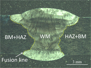
Figure 1 illustrates the overall macrostructure of the welded joint. The welded joint of IN 617 is consisted of BM, HAZ, and WM. The obvious columnar crystal can be observed in the center of WM. Some equiaxed grains were characterized on both sides of the up and down because of the change of heat dissipation direction in the late of weld metal solidification. And BM and HAZ are hard to be distinguished by low magnification OM, which will be described as follows.
The overall macrostructure of the alloy 617 welded joint.

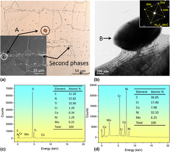
The microstructure features of IN 617 alloy are shown in Fig. 2(a), which exhibit a significant banded structure. This microstructure is characterized by austenitic grains and a series of secondary phases both along the grain boundaries and in the interior of grains. A small number of discrete polyhedral secondary particles with a size of about 10 μm [pointed out by arrow in Fig. 2(a)] are identified as Ti(C, N), as displayed in Figs. 2(a) and 2(c). The size of these particles was about 5–10 μm. A large number of globular particles with a smaller size of about 2–4 μm are identified as M23C6 carbides enriched with Mo and Cr, which are characterized by TEM in Figs. 2(b) and 2(d). These particles appeared both along grain boundaries and in the interior of grains. In addition to the microstructural features mentioned above, the annealing twin structure in grains interrupted the whole grain side by side. Reference Kimball, Lai and Reynolds6,Reference Lin, Jin, Hefferan, Li, Lind, Suter, Bernacki, Bozzolo, Rollett and Rohrer16,Reference Wang, Lartigue-Korinek, Brisset, Helbert, Bourgon and Baudin17 And also few amount of fine carbides distributed along with the twins.
The microstructure of alloy 617 BM. (a) The OM and SEM image of alloy 617 BM, (b) the TEM image of the small carbide in alloy 617, (c) the EDS results of A point in (a), (d) the EDS results of B point in (b).

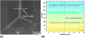
Figure 3 displays the microstructure and EDS line scan results across the grain boundaries in BM. Some fine second phase particles present along the grain boundaries. Figure 3(b) reveals that no obvious element segregation is observed in this area.
The microstructure and line scan results of the grain boundaries in BM. (a) The SEM image of the grain boundaries, (b) the EDS line results of the grain boundaries. No obvious element segregation is observed.

B. The microstructure and element segregation of HAZ
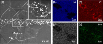
Figure 4 shows the microstructure of HAZ near to BM. The fine M23C6 carbides still exit at grain boundaries and in the interior of grains along rolling direction. However, coarse M23C6 carbides with 15–30 μm size are present along grain boundaries. The number of fine carbides around the coarse ones decreases comparing with the other zones. Figures 4(b)–4(e) reveal the EDS results of the coarse carbides. The elements such as Ni and Co are depleted while the Cr and Mo are enriched in the coarse carbides. The Cr and Mo in IN 617 are the solid solution strengthening elements. These elements have much stronger binding force with C element than Ni and Co elements. Hence, these elements always are enriched in carbides. It should be noted that the Cr element is found mainly in the small carbides and the outer of the coarse carbides while the Mo element is enriched in the inner of the coarse carbides.
The microstructure of the HAZ in the vicinity of BM. (a) The coarsened carbides in this area with a size of 10–15 μm, (b)–(e) the EDS map scan results of the coarsened carbides.

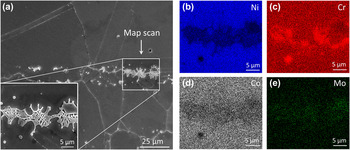
The microstructure of the HAZ in the vicinity of the fusion line is shown in Fig. 5(a). Several continuous lamellar structures at the grain boundary could be observed. The amounts of fine M23C6 carbides both along the grain boundaries and inside the grains are dramatically reduced. The EDS results of this area are presented in Figs. 5(b)–5(e). Pronounced segregation of Cr and Mo is found in the lamellar structure. Our previous research has deemed that the lamellar structures mainly form at high peak temperature above 1300 °C during welding. Reference Liu, Lu, Yang, Tang and Cui18 The formation of the lamellar structure is attributed to the constitutional liquation of the second phase particles during welding. Reference Oh, Yoo, Choi, Santella and Jang19 Constitutional liquation is a nonequilibrium subsolidus eutectic melting phenomenon at chemically heterogeneous regions of the matrix. This phenomenon exists in many commercial alloy systems. The constitutional liquation reaction occurs always between a second phase particle and the surrounding matrix and produces a metastable solute rich liquid film at the particle/matrix interface. Reference Jiang and Liu20,Reference Kuźnicka21 In this investigation, the main segregation elements include Cr and Mo. The carbides inside grains are metastable and tend to dissolve at high temperature. And the carbides appeared at grain boundaries are more stable which grow and coarsen due to the dissolution of carbides inside grains. Reference Kimball, Lai and Reynolds6 Ye et al. pointed out that the dissolution of M23C6 precipitates was the primary diffusion process. The concentration of carbon (C) and solid solution elements, such as Cr and Mo, in austenitic matrix increases due to the dissolution of the carbides inside grains at the high peak temperature. Reference Ye, Hua, Wu and Lou22 C atoms with a small atomic radius tend to be located in the interstitial sites of the austenitic lattice and interstitially diffused with fast speed. Lipnitskii et al. reported that alloy elements diffused faster in the boundary area and precipitated easily from austenite than inside the grains. Reference Lipnitskii, Nelasov, Golosov, Kolobov and Maradudin23 Hence, alloy element and C are enriched at austenitic grain boundaries as the carbides inside grains dissoluted at high temperature. At the HAZ adjacent to BM, the peak temperature could reach 1250 °C which is lower than eutectic temperature, therefore several coarse carbides form in this area and elements segregation happens along grains. However, at the area in the vicinity of fusion line with higher peak temperature over eutectic temperature, constitutional liquation occurs attributing to the alloy elements enriched at the particle/matrix interface and rapid heating. Liquid will be formed and then spread along grain boundaries through intersection of grain boundaries with liquated regions in the matrix. Reference Bermingham, McDonald, StJohn and Dargusch24 As the temperature decreases, the continuous lamellar structure will be formed along boundaries.
The microstructure of the HAZ in the vicinity of fusion line. (a) Continuous lamellar structure, and (b)–(e) the EDS map scan results of the continuous lamellar structure.

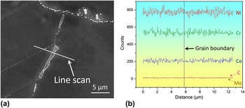
Figure 6 displays the microstructure and line scan results of the grain boundaries in HAZ. As mentioned above, some phenomena happened during welding process such as second phase dissolution and alloy element segregation along grain boundaries. However, the diffusion distance of alloy elements is very short due to the shorter duration time at high temperature. Hence, the EDS line scan results of the grain boundary away from second phases show that no obvious element segregation is detected.
The microstructure and line scan results of the grain boundaries in HAZ. (a) The SEM image of the grain boundaries, and (b) the EDS line results of the grain boundaries. No obvious element segregation is observed.

C. The microstructure and element segregation of WM
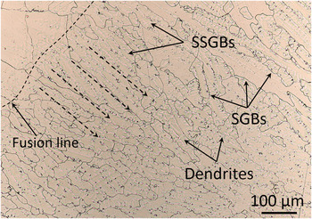
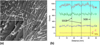
Two different boundary types can be observed in the OM image of the WM. The solidification grain boundary (SGB) results from the intersection of subgrains. The solidification subgrains represent the finest structure in the OM image. These subgrains normally present as dendrites and the boundary separating adjacent subgrains are known as a solidification subgrain boundary (SSGB), as shown in Fig. 7. The weldability and mechanical properties of the welded joint depend greatly on the solidification behavior and microstructure of the WM. The microstructure, as shown in Figs. 7 and 8(a), illustrates a typical dendritic substructure with obvious growth direction. The width of dendrite is about 10–20 μm and several fine second phases exist along the SGBs.
The OM image of microstructure of the WM. Two different boundary types, SSGBs and SGBs, can be observed. Dotted line arrows show the growth direction of dendrites.

The microstructure and EDS line scan results of WM. (a) The SEM image of the WM. SSGBs and SGBs can be observed obviously, and (b) EDS line scan results show alloy elements mainly segregate along SSGBs.

The distribution of alloy elements across the dendritic substructure is analyzed by EDS line scan method. The equilibrium distribution coefficient of alloy elements can be effectively assessed with the solute redistribution during solidification. In IN 617, the equilibrium distribution coefficient of Cr and Mo is lower than 1, therefore the content of Cr and Mo should have steep concentration gradients across the austenite grain and dendritic substructure boundaries. However, the EDS line scan results, as displayed in Fig. 8(b), reveal that the area in the vicinity of SGBs and SSGBs has a local depletion of Ni and Co while the Cr and Mo have no obvious segregation.
D. The mechanical properties of the welded joint
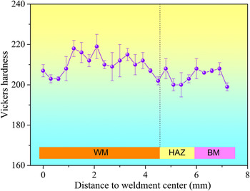
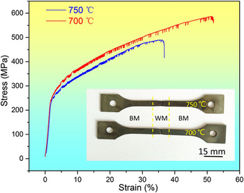
The microhardness and high temperature tensile test were conducted to evaluate the mechanical properties of the welded joint. Figure 9 shows the results of the microhardness test of the welded joint. The average hardness value of BM, HAZ, and WM is 205.6, 201, and 211.5 HV, respectively. According to the Hall–Petch relationship, hardness decreased with the increase of grain size at room temperature. Reference Takaki, Kawasaki and Kimura25 As our previous work, the size of austenite grain has no significant change in HAZ comparing with BM. Reference Liu, Lu, Yang, Tang and Cui18 Meanwhile, for IN 617 which is a solid-solution strengthened superalloy, the content of solid-solution elements in the austenite matrix, such as Cr, Mo and Co, is a main factor in the determination of hardness. Dissolution of carbides inside grains and enrichment of alloy elements along grain boundaries lead to little variation in the content of solid solution elements. But, the grain size of BM is larger than WM. The SSGBs in WM also have a strengthening effect. Hence, the hardness value of WM is slightly higher than BM. Figure 10 shows the high temperature tensile test results at 700 and 750 °C. The fracture position is determined in the middle of WM. The yield stress and ultimate tensile stress of welded joint is 233 and 490 MPa at 750 °C, respectively, and 240 and 587 MPa at 700 °C. In our pervious work, Reference Lin, Jin, Hefferan, Li, Lind, Suter, Bernacki, Bozzolo, Rollett and Rohrer16 the yield stress and ultimate tensile stress of BM is 257 and 512 MPa at 750 °C, respectively. The results show that the welded joint has a close high temperature performance to BM. TIG is a suitable welding method for IN 617.
The results of micro-hardness test of the Inconel 617 alloy TIG welded joint.

The high temperature tensile test results of IN 617 welded joint. The yield stress and ultimate tensile stress at 700 °C is 240 and 587 MPa, as well as 233 and 490 MPa at 750 °C.

IV. CONCLUSIONS
The microstructure, element segregation and mechanical properties of IN 617 TIG welded joint was elaborately investigated in this research. Based on the results, some conclusions can be drawn as follows:
-
(1) The microstructure of WM was a typical dendritic substructure with obvious growth direction. For the HAZ in the vicinity of fusion line, continuous lamellar structure forms along austenitic grain boundaries, attributing to the constitutional liquation of the second phase particles during welding. The coarse carbides along grain boundaries occurred in HAZ near to BM.
-
(2) The WM has a little bit larger hardness value than BM and HAZ because of the strengthening effect of SSGBs. The carbides inside grains vanish, and a continuous lamellar structure occurs at the grain boundaries, leading to the lower hardness of the welded joint. The high temperature tensile properties of the welded joint are close to BM. The fracture position is determined in the middle of WM, which is attributed to the grain boundary failure in the center of WM. TIG welding method is proved to be a suitable welding method to join IN 617.
-
(3) No obvious element segregation was found along austenite grain boundaries for BM and HAZ. In WM, the area in the vicinity of SGBs and SSGBs has a local depletion of Ni and Co while the Cr and Mo have no obvious segregation.