I. INTRODUCTION
Lasers are used for the local annealing, sintering, and melting of polymeric, metallic, and ceramic powders in so called additive manufacturing (AM) processes. AM describes a class of technologies in which a 3D object is directly generated from a virtual model by adding material in a layer-by-layer approach 1 and is defined by ASTM F2792 - 12a (Standard Terminology for AM Technologies) as the “process of joining materials to make objects from 3D model data, usually layer upon layer, opposed to subtractive manufacturing methodologies, such as traditional machining.”
The present study has been motivated by the idea to locally manipulate a ceramic powder compact within its volume by laser light, i.e., light can be locally dissipated into heat to initiate sintering selectively. With such an approach structures could be directly inscribed into the volume of a ceramic compact avoiding the time consuming buildup in a layer-by-layer fashion intrinsic to the majority of AM technologies. Compared with polymers and metals, ceramic materials are unique as they offer a wide optical window of transparency, typically ranging from below 0.3–5 µm wave length. Reference Wei2 This in principle enables the transfer of energy by laser light into the volume of a defect-free ceramic body. On the other hand, porous ceramic bodies, such as powder compacts, tend to reflect the incoming light because of an intensive light scattering at the pores.
We have examined the interaction of light with ceramic (amorphous silica) particles. Even though a considerable amount of literature is devoted to the interaction of light with ceramic particles from a geoscience and spectroscopic perspective, e.g., ref. Reference Salisbury and Wald3–Reference Kokhanovsky5 and the literature cited herein, the transmission of light through powder compacts of a transparent material has not been addressed in detail.
The description of the interaction between light and a porous material requires the precise knowledge of the complex index of refraction ñ = n + iK of the material and the pore filling medium where ñ is given by the optical constants n (refractive index) and K (extinction coefficient). The optical properties of porous materials are governed by light scattering and absorption.5–7 In the case of ceramic powder compacts, scattering takes place at the interfaces between air-filled pores and powder particles. Absorption occurs within the ceramic material itself and is expressed by K, i.e., by the imaginary part of ñ. K is a material constant and indicates the amount of the absorption loss when the electromagnetic wave propagates through a solid. K is directly proportional to the absorption coefficient α in Lambert's law of absorption I(x) = I 0exp(−αx) and depends on the wave length of the light. Large value for K corresponds to high absorption losses.
The wave lengths of the two most common technical laser types are approximately 10 µm for CO2 lasers and 1 µm for most technically relevant solid state lasers. For ceramic materials K is generally large at wave lengths around 10 µm and, therefore, CO2 laser radiation is readily absorbed. On the other hand, a wave length of 1 µm is well located in the middle of the optical window of most ceramic materials and K is close to zero, i.e., absorption losses are generally small.
The interaction of a porous ceramic body, such as a powder compact, with CO2 laser radiation is governed by absorption. The penetration depth of the laser light is in the range of the lasers wave length, that is, 10 µm. Reference Gräf, Staupendahl, Gerinling and Müller8 If K is close to zero and light absorption is weak the interaction of laser radiation with ceramic powder compacts is governed by scattering. In this case, the corresponding real parts n of the ceramic material and the pore-filling medium, and the particle size are the critical parameters.
For pore sizes significantly larger than the wave length of the interacting light, scattering is governed by classical optics. Reference Melamed9 According to Fresnel's formulas the difference of n of the ceramic material (n ≈ 1.5) and the air filling the pores (n ≈ 1) at λ ≈ 1 µm results in a significant reflection at the air–ceramic interface. On the other hand, for pore sizes in the range of the wave length of the interacting light, light scattering is described by Mie theory (of scattering of electromagnetic waves) Reference Kokhanovsky5,Reference Bohren6 and entire pores can be considered as individual scattering centers. Reference Mustard and Hays4 Here, most intensity is reflected and absorption is only possible near the surface of the powder compact under the premise that the ceramic material absorbs some energy. For both particle size regimes, the introduction of energy by laser light into the volume of a ceramic powder compact is difficult even if the ceramic material itself is transparent for the given wave length.
However, pores about 10 times smaller in size than the wave length of the interacting light are not recognized by the incident electromagnetic wave as individual scattering centers. Merely, their concentration affects the index of refraction n of the porous body itself. Reference Bohren and Huffman7,Reference Adam10 Thus, in this pore size regime transmission of light trough a porous body is possible. E.g., antireflective coatings made of silica are taking advantage of this fact: The value of n of the coating is tuned by the concentration of air-filled pores, a few nanometers in size, to reach approximately n = 1.2, while n of the supporting glass substrate itself is about 1.5.
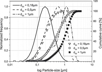
For investigating the optical properties of ceramic compacts more in detail, thin layers of compacted particles deposited by dip and spray coating onto quartz glass substrates have been investigated. From the so-prepared samples, transmission and reflection spectra between 0.5 and 2.5 µm wave lengths have been recorded in the particularly interesting particle size regimen between 0.18 and 10 µm (d 50). At this point it is important to point out that the used particle size fractions are not ideally uniform in size. Instead they have a monomodal particle size distribution, see also Fig. 1. Nonetheless, clear trends in the optical properties as a function of the average particle size could be observed, as introduced in the following.
Grain size distribution of SiO2 powders used in the present study.

II. EXPERIMENTAL SECTION
For all experiments amorphous silica particles have been used. The particles 0.5, 1, and 10 µm in diameter are obtained by attrition milling high-purity silica powder from Mitsubishi Inc. with a mean particle size of 400 µm (Type: Mitsubishi MKC 400, Mitsubishi Materials Corporation, Tokyo, Japan). The particles obtained are monodisperse and have a nearly spherical morphology. The 0.18 µm particles are perfectly spherical and purchased from Corning Inc. (Type: Corning Soot, Corning, NY).
Low solid content suspensions between 5 and 20 wt% for dip coating and between 5 and 10 wt% for spray coating have been prepared by dispersing the silica particles in ethanol and isopropanol mixtures. The particle size distribution of each individual powder has been determined by a Beckman Coulter LS 230 instrument (Coulter Corporation, Miami, FL) and is presented in Fig. 1. Dip coating has been performed with the following parameters: Dipping and pulling speed between 2 and 5 mm/s, holding time 10 s, and dip repeating 5–20 times. Different layer thicknesses have been achieved by varying the pulling speed, the solid content of the suspensions, and by multiple dipping.
With an increasing solid content more particles are carried away by pulling the sample carrier out of the suspension. A higher pulling speed yields higher layer thicknesses, as more suspension can adhere to the sample carrier. The maximum thickness of homogeneous crack free layers achievable by dip coating is 50 µm. For the powder with particle size of d 50 = 10 µm, preparation of stable suspensions with low solid contents was not successful. Therefore, layers of this powder have been prepared by spray coating. The thickness of the as-prepared layers has been determined employing a Keyence VK-9710 3D Laser Scanning Microscope (Itasca, IL).
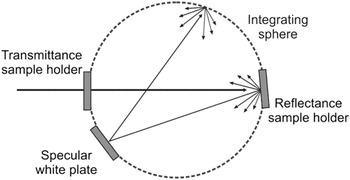
For all layers, 2 mm thick high-purity quartz glass sheets (sample size 20 × 50 mm) have served as supporting substrates. For recording transmission and reflection spectra a PerkinElmer Lambda 950 spectrometer (Shelton, CT) equipped with a 150 mm integrating sphere has been used. A schematic of the setup for measuring the optical properties is illustrated in Fig. 2.
Schematic of the experimental setup used for transmission and reflectance measurements.

III. RESULTS AND DISCUSSION
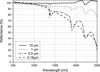
Figure 3 compares the reflected intensities of powder compacts formed from silica powders with maximum 10 µm (d 50) and minimum 0.18 µm (d 50) in size. The thickness of the tablet shaped samples was 4 mm. Clearly visible is a high reflectance of the 10 µm powder sample over the entire wave length range. On the other hand, the samples consisting of the finer powders reveal a continuous decrease in reflected intensity toward increasing wave length: With increasing wave length scattering at the nanometer size pores becomes increasingly ineffective and light is transmitted into and through the sample, as transmission spectra reveal (not shown here).
Comparison of reflection spectra taken from powder compacts 4 mm in thickness and made of silica powders with a mean particle size of 0.18, 0.5, 1, and 10 µm, respectively.

To learn how deep light can penetrate into a powder compact as a function of the wave length of the incident light and the particle size, layers of different thickness have been prepared from three powders with different mean particle sizes, that are, 0.18, 0.5, and 1 µm. All powders show a monomodal particle size distribution which was kept as narrow as possible to make the results significant for a certain particle size.
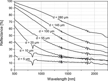
Figure 4 presents a sequence of reflection spectra taken from layers of fine particles (0.18 µm) with different thickness. It is clearly noticeable that toward larger wave lengths a continuous decrease in reflected intensity occurs for all layers thicknesses. Zero reflectance of the layers in Fig. 4 corresponds to approximately 10%, as the supporting glass substrate contributes to the total reflectance by about this value in the measured wave length range. Also some prominent features are noticeable in the spectra. As these features are losing intensity with increasing layer thickness or even vanish, they can be attributed to a resonant light absorption within the supporting glass substrate or at the layer–substrate interface.
Sequence of reflection spectra taken from powder layers of different thickness made of a fine (d 50 = 0.18 µm) silica powder.

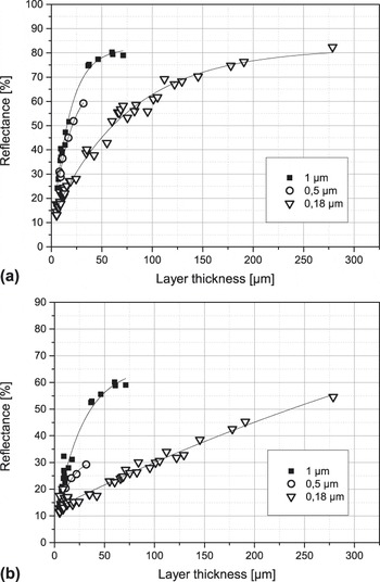
Figure 5 summarizes reflection intensities for two given wave lengths of the incident light, 1070 and 1950 nm. The reflected intensities are plotted as a function of the layer thickness. Data for the three mean particle sizes d 50 = 0.18, 0.5, and 1 µm are shown. The data are extracted from individual reflection spectra as presented in Fig. 4. The two wave lengths have been chosen, because they are located well in the middle of the transparency window of silica and are supplied by commercial laser systems, with the 1950 nm available very recently. As a function of the layer thickness x, the reflected intensities reveal a type 1 − exp (−αx) behavior for a given mean particle size. Assuming that for high-purity silica there is very little absorption to be considered for the investigated layer thicknesses, the sum of reflected (I R) and transmitted (I T) intensity will yield the incident intensity I 0:
 $${I_0} = {I_{\rm{R}}} + {I_{\rm{T}}}\quad {\rm{.}}$$
Reflected intensities as a function of layer thickness and particle size for two given wave lengths of the incident light: (a) 1070 nm and (b) 1950 nm.

Accordingly, the corresponding transmission spectra show an exponential decrease in transmitted intensity upon increasing layer thickness. The data sets for the transmitted intensity as a function of layer thickness (not shown here) can be fitted by the simple relation:
 $${I_{\rm{T}}} = {I_0}\;{\rm{exp}}( - \alpha x)\quad {\rm{,}}$$
with I T the transmitted intensity, I 0 the initial intensity of the incident light, α a decay constant, and x the layer thickness. Since the layer thickness is equivalent to a penetration depth of the light into a powder compact, Eq. (2) basically reflects the Lambert–Beer law, describing the logarithmic decay of intensity of light passing through a substance, with log (I T/I 0) proportional to the product of the absorption coefficient of the substance, α, and the distance the light travels through the material, i.e., the path length x. By comparing the six graphs in Fig. 5 it becomes evident that α must depend on the particle size and the wave length of the incident light in the following form:
 $$\alpha = b({d \mathord{\left/ {\vphantom {d \lambda }} \right. \kern-\nulldelimiterspace} \lambda })\quad {\rm{,}}$$
with d the mean particle size, λ the wave length of the incident light, and b a proportional factor.
Now, Eq. (2) can be expressed in the following form:
 $${I_{\rm{T}}} = {I_0}\;{\rm{exp}}\left( { - b\left( {{d \mathord{\left/ {\vphantom {d \lambda }} \right. \kern-\nulldelimiterspace} \lambda }} \right)x} \right)\quad {\rm{.}}$$
Combining Eqs. (1) and (4) leads to the following expression for the reflected intensity I R:
 $${I_{\rm{R}}} = {I_0}\left[ {1 - {\rm{exp}}\left( { - b\left( {{d \mathord{\left/ {\vphantom {d \lambda }} \right. \kern-\nulldelimiterspace} \lambda }} \right)x} \right)} \right]\quad {\rm{.}}$$
To validate this relation, two graphs in Fig. 5 can be compared: The graph for the 0.5 µm powder in Fig. 5(a) and the one for the 1 µm powder in Fig. 5(b). For both graphs the ratio between particle size and wave length of the incident light is nearly the same, that is, 0.5. The good match between the two data sets in Fig. 5 supports the viewpoint that d/λ is a critical parameter for the light transmission into the volume of a powder compact. Together with the path length of the light, they determine the amount of energy available at a respective volume element within a powder compact. Also, in Fig. 5 it is clearly noticeable that for a given particle size the penetration depth of the light with 1950 nm wave length is higher than 1070 nm wave length. In particular, only 50% are backscattered at about 250 µm layer thickness for 1950 nm wave length at 0.18 µm particle size. These results are opening a process window for the preparation of ceramic powder compacts which can be manipulated by light locally within their volume: Focusing light into a certain volume element and tuning the absorbance of the powder compact in an appropriate manner enables a local thermal treatment.
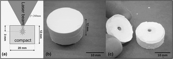
In a preliminary experiment a fiber laser (IPG, 1950 nm, 50 W cw.) has been used to anneal a certain volume element within a SiO2 powder compact. The setup is illustrated in Fig. 6(a). The cylindrical compact, 12 mm in height and 20 mm in diameter, made of a Corning Soot (Corning Inc.) powder with a mean particle size of 0.18 µm has been prepared by uniaxial compaction using polyethylene glycol (PEG) as a pressing agent. The PEG acts as binder, but also enables the coupling of the laser light to the powder compact. Therefore, some energy of the laser light is absorbed and dissipated into heat within the powder compacts volume. Focusing the laser beam into the volume of the compact allows a selective annealing of a volume element within the compact. It is noteworthy that for calculating the precise position of the laser focus in the compact, the compacts refractive index, at the wave length of the laser used, must be known. In the configuration shown in Fig. 6(a) the focal point is moved, according to Snell's law of refraction, slightly deeper into the sample than expected from the focal length f = 260 mm of the used optics. While Fig. 6(b) shows the compact after the laser treatment with no obvious sintering at its outer contour, Fig. 6(c) clearly reveals that sintering has taken place within the volume of the compact. About 3 mm below the irradiated surface of the compact, a hot spot has been formed and a volume element of about 1 mm3 has been compacted to a dense structure. This experiment can be understood as proof of concept, even though the volumetric resolution (about 1 mm3, sintered volume element in Fig. 6) is not sufficient for establishing sophisticated structures within the compact’s volume. The unaffected material can be easily separated from the sintered by sonication of the entire structure in an ultrasonic bath. Further research will be devoted to effectively control the temperature during laser sintering, serving the purpose of a higher definition of the sintering process and establishing a well-defined sintering state of the ceramic material. In this context, it is planned to use a thermo camera operating at a wave length at which the powder compact is transparent.
a) Schematic of the laser setup for annealing a volume element of a powder compact. b) Powder compact after laser treatment. c) Compact opened at a crack formed during the laser treatment.

IV. CONCLUSION
The present work demonstrates the possibility of selectively sintering volume elements in a ceramic powder compact with lasers as energy source. Powder compacts made of fine silica particles are offering sufficient transparency for the SVS process. The success of this work is based on right choice of laser wave length and particle size of the powder compact. The results presented can be generalized for all wide band gap insulators.