Introduction
Solid-state cooling with caloric materials is a viable alternative to conventional vapor compression, and has the potential to take on a sizable share of the worldwide market in heating, ventilation, and air conditioning technologies.Reference Takeuchi and Sandeman1–Reference Moya, Kar-Narayan and Mathur3 Caloric materials are categorized as magnetocaloric, electrocaloric, or mechanocaloric when the cooling effect is driven by a magnetic, an electric, or a mechanical field, respectively. Mechanocaloric materials are further divided into elastocaloric materials, wherein uniaxial mechanical stress is used, and barocaloric materials, where isotropic stress such as hydrostatic pressure is applied to the material.Reference Moya, Kar-Narayan and Mathur3,Reference Mañosa and Planes4 The first observation of the elastocaloric effect was probably on a piece of rubber dating back to 1859;Reference Moya, Kar-Narayan and Mathur3 however, the systematic demonstration of elastocaloric cooling using shape-memory materials began only recently in 2012.Reference Cui, Wu, Muehlbauer, Hwang, Radermacher, Fackler, Wuttig and Takeuchi5,Reference Bechtold, Chluba, De Miranda and Quandt6
The elastocaloric effect exhibits remarkable potential as manifested in the directly measured cooling ΔT of −17°C in Ni-Ti,Reference Cui, Wu, Muehlbauer, Hwang, Radermacher, Fackler, Wuttig and Takeuchi5 a level not easily achievable by other caloric materials. The exploration of elastocaloric materials has now been expanded from Ni–Ti-based alloys to Cu-based alloys and various magnetic alloys.Reference Hou, Simsek, Stasak, Hasan, Qian, Ott, Cui and Takeuchi7 At the same time, elastocaloric cooling system prototypes have been demonstrated based on tensile,Reference Tušek, Engelbrecht, Eriksen, Dall’Olio, Tušek and Pryds8 compressive,Reference Qian, Alabdulkarem, Ling, Muehlbauer, Hwang, Radermacher and Takeuchi9 and bending modes.Reference Ossmer, Wendler, Gueltig, Lambrecht, Miyazaki and Kohl10
Elastocaloric cooling is based on shape-memory alloys (SMAs). An SMA is able to “remember” its original shape when heated above its martensitic transformation temperature.Reference Otsuka and Ren11 SMAs in the austenite phase exhibit superelasticity where stress-induced phase transformation leads to a large reversible strain. Elastocaloric cooling takes place when the latent heat is absorbed back in the material during the reverse transformation from martensite to austenite in the unloading part of superelasticity.Reference Cui, Wu, Muehlbauer, Hwang, Radermacher, Fackler, Wuttig and Takeuchi5,Reference Hou, Simsek, Stasak, Hasan, Qian, Ott, Cui and Takeuchi7 Continuous operation of elastocaloric cooling requires repetitive application of stress to SMAs, and the large number of mechanical loading cycles can potentially lead to onset of fatigue. Fatigue causes deterioration of mechanical properties of a material and eventual failure under cyclic application of mechanical loads.Reference Meyers and Chawla12
In this article, we highlight recent efforts in overcoming fatigue associated with SMAs used in elastocaloric cooling, from fundamental mechanisms to the design of cooling devices and systems. The microstructural origins of fatigue and possible pathways to extend fatigue lives are reviewed from the perspective of solid mechanics. We describe tension-compression asymmetry unique to SMAs in terms of microstructural orientation dependence and macroscopic behavior. We explain the geometry and assembly of SMAs customized for compression-based elastocaloric devices and an accompanying heat-transfer subsystem. We address work recovery and related considerations for designing elastocaloric prototype systems. The directly measured cooling ΔT of various SMAs over cyclic loading is summarized.
Mechanisms of fatigue and relation to loading mode
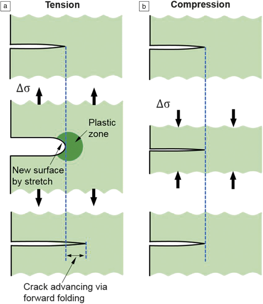
The origin of fatigue is the initiation of cracks and their eventual propagation.Reference Meyers and Chawla12,Reference Ashby, Shercliff and Cebon13 Compared to crack initiation, crack propagation can take place for a long period of time before eventual failure.Reference Meyers and Chawla12 Slowing crack propagation is essential for maintaining the material’s integrity over many cycles. Figure 1a illustrates the crack propagation after a large number of repetitive tensile stress cycles. The already initiated crack has a stress concentration around the tip of the crack. The stresses at the exact tip of a crack exhibit extremely large values and in theory approach infinity.Reference Meyers and Chawla12 This is considerably higher than the yield strength of the material. A plastic zone arises in the vicinity of the crack tip with the ability to deform substantially, and the crack tip increases the radius of curvature in order to relax the stress concentration. Under tensile stress, new surfaces can be stretched out of the plastically deformed region with a blunt crack tip.Reference Ashby, Shercliff and Cebon13 Upon removing the tensile stress, the newly generated surfaces require additional space to fold in, and thus they advance along the direction perpendicular to the axis of tensile stress. The advancing process repeats in the subsequent loading–unloading cycles.
Mechanisms of crack propagation. Schematic of crack advancing under (a) tensile and (b) compressive cycles with stress amplitude Δσ. Adapted with permission from Reference Ashby, Shercliff and CebonReference 13. © 2007 Elsevier.

On the other hand, compressive loading (Figure 1b) can delay the advancing of cracks by curtailing the driving force for generation of new surfaces. The extension of crack length can be slowed down in subsequent cycles. Furthermore, creating a thin, compressive layer on a material surface can improve fatigue strength up to 60%Reference Zhang and Lindemann14 and extend fatigue life nearly three times.Reference Luong and Hill15 Therefore, compressive stress is an effective route to prolong the fatigue life of materials.
Mechanism of tension–compression asymmetry
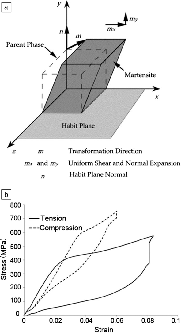
Stress-induced martensitic transformation can be achieved through compressive or tensile stress. Figure 2aReference Gall and Sehitoglu16 shows the parameters in a single-crystal transformation from austenite (labeled “parent phase”) to martensite. On the habit plane (an unrotated and undistorted plane), the maximum shear stress resolved from the external load can align positively or negatively with respect to the prescribed transformation direction.Reference Gall, Sehitoglu, Chumlyakov and Kireeva17
Tension–compression asymmetry in shape-memory alloys. (a) Schematic showing transformation parameters of favorably oriented martensite in stress-induced martensitic transformation. Reproduced with permission from Reference Reference Gall and Sehitoglu16. © 1999 Elsevier. (b) Superelastic stress–strain curves obtained for polycrystalline Ni-Ti when applying tensile and compressive stress within the austenite state.Reference Cui, Wu, Muehlbauer, Hwang, Radermacher, Fackler, Wuttig and Takeuchi5

The shear component of the transformation direction can dominate over the normal component when there is only a slight volume change in single-crystal Ni-Ti.Reference Buchheit and Wert18 The crystallographic constraints permit the martensitic transformation to initiate if the maximum resolved shear stress is positive toward the prescribed transformation shear direction.Reference Gall, Sehitoglu, Chumlyakov and Kireeva17,Reference Gall, Sehitoglu, Anderson, Karaman, Chumlyakov and Kireeva19 As a result, the martensitic transformation exhibits a unidirectional nature at a crystallographic orientation for a given stress state, and has strong tension–compression asymmetry for a single crystal.Reference Gall, Sehitoglu, Chumlyakov and Kireeva17
When crystals are aggregated into textured polycrystals as commonly encountered in drawn wires or bars,Reference Gall and Sehitoglu16,Reference Liu, Xie, Van Humbeeck and Delaey20 the tension–compression asymmetry due to the strong texturing is expected to be similar to the asymmetry resulting from crystallographic orientation dependence in single crystals. The compressive superelasticity of polycrystalline Ni-Ti wires in Figure 2b shows higher critical transformation stresses, greater transformation stress–strain slopes, and smaller transformation strains than those in tension. The difference is attributed to the dependence of the maximum resolved shear stress on crystallographic orientation and the stress direction.Reference Gall and Sehitoglu16,Reference Gall, Sehitoglu, Chumlyakov and Kireeva17 For example, the [111] orientation in polycrystalline Ni-Ti has the maximum value of the orientation tensor (or Schmid factorReference Gall, Sehitoglu, Anderson, Karaman, Chumlyakov and Kireeva19) of 0.39 for tension versus 0.27 for compression, while the [100] direction has values of 0.21 for tension versus 0.4 for compression. The larger the maximum value of the orientation tensor, the higher the effective conversion and thus the smaller the required applied stress.Reference Gall and Sehitoglu16 Since the entire austenite domain is converted into martensiteReference Sehitoglu, Wu and Ertekin21 and the cooling potential dictated by the latent heat (on the order of 10 J g−1 for Ni-Ti alloysReference Cui, Wu, Muehlbauer, Hwang, Radermacher, Fackler, Wuttig and Takeuchi5,Reference Hou, Simsek, Stasak, Hasan, Qian, Ott, Cui and Takeuchi7 ) is fully unleashed, compression can deliver the same cooling capacity as tension and extend the fatigue life despite the necessary high transformation stress and the large transformation stress–strain slope.
Compression-based design of elastocaloric materials
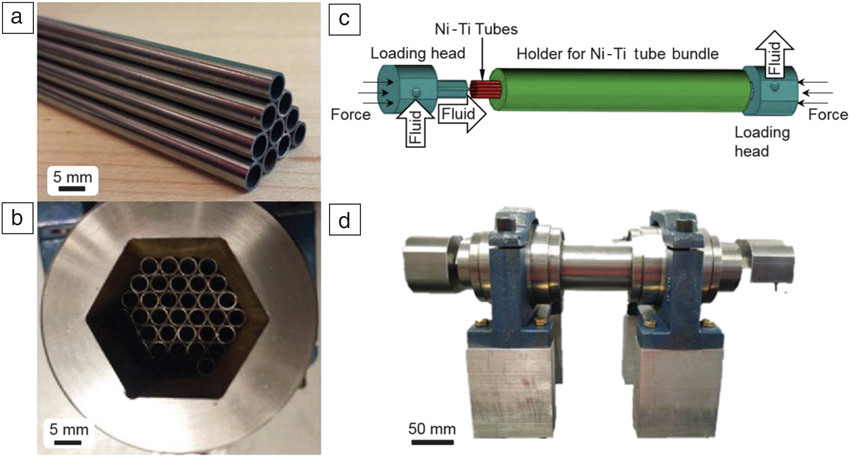
The understanding of the benefits of compression motivates the utilization in designing cooling devices with SMAs as the solid refrigerant.Reference Qian, Alabdulkarem, Ling, Muehlbauer, Hwang, Radermacher and Takeuchi9,Reference Qian, Geng, Wang, Muehlbauer, Ling, Hwang, Radermacher and Takeuchi22 SMA tubes have been chosen as refrigerant components to allow the cooling medium (typically water) to flow through. Figure 3aReference Qian, Geng, Wang, Muehlbauer, Ling, Hwang, Radermacher and Takeuchi22 shows one example configuration of the SMA tubes in a bundle. To prevent buckling (a common failure mode under compression), the tubes are grouped into a hexagonal cross-sectional shape preserving symmetrically distributed stress, and a rigid holder is employed for lateral mechanical support (Figure 3bReference Qian23). After cooling is generated in the bundle of SMA tubes, heat-transfer fluid carries the heat. Additional components to compress tubes with fluid flowing are illustrated in Figure 3c. Figure 3d shows the completed Ni-Ti tube bundles supported by linear bearings to ensure axially compressive loading. A cooling capacity of 100 W can be generated in one bundle with twenty 250-mm-long Ni-Ti tubes with outer diameter of 4.7 mm, inner diameter of 3.8 mm, and latent heat of 12 J g−1 operated at 0.1 Hz.Reference Qian, Alabdulkarem, Ling, Muehlbauer, Hwang, Radermacher and Takeuchi9 The cooling power scales proportionally with the total material mass and with the operation frequency.Reference Qian, Geng, Wang, Muehlbauer, Ling, Hwang, Radermacher and Takeuchi22
Compression-based design of Ni-Ti materials for elastocaloric systems. (a) Geometry of Ni-Ti tubes and a stack of multiple tubes and (b) assembly of a bundle of Ni-Ti tubes into a holder to prevent buckling.Reference Qian, Geng, Wang, Muehlbauer, Ling, Hwang, Radermacher and Takeuchi22,Reference Qian23 (c) Schematic of Ni-Ti bundles and loading heads. The heat exchange fluid is made to flow through the tubes for heat transfer.Reference Qian, Alabdulkarem, Ling, Muehlbauer, Hwang, Radermacher and Takeuchi9 (d) Picture of final assembly of the loading heads and Ni-Ti bundles in a linearly aligned configuration for an elastocaloric system.Reference Qian, Geng, Wang, Muehlbauer, Ling, Hwang, Radermacher and Takeuchi22

Designing compression-based elastocaloric systems
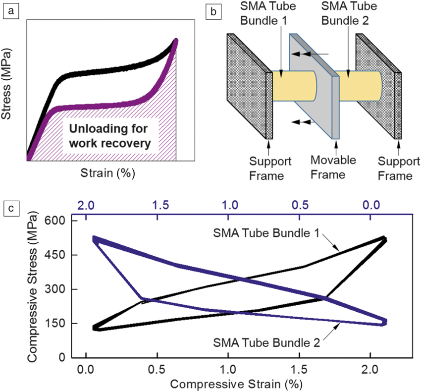
Full recovery of strain in SMAs upon unloading is shown in Figure 4a. A mechanical system can be devised so that unloading force in one material can be harnessed as a part of the driving stress for another material. The configuration in Figure 4b is realized by axially aligning two SMA tube bundles. Each bundle is initially in a compressed state with half of the maximum reversible strain. When bundle 1 is compressed by means of an input actuation mechanism applied via the movable frame, the unloading force from half strain to zero strain of bundle 2 assists in driving the movable frame so that the required input work for bundle 1 is reduced. This process is called work recovery. When bundle 1 is loaded to reject heat, bundle 2 is unloaded to absorb heat and deliver cooling, which repeats in a reciprocating manner. Figure 4c depicts experimental stress–strain curves for the two SMA bundles during one cycle of operation of the prototype. When strain is increased in bundle 1, strain is decreased in bundle 2 in a synchronized manner. A process of heat recovery can also be implemented to improve the heat-exchange efficiency of the entire system.Reference Qian, Ling, Muehlbauer, Hwang and Radermacher24 Optimization of the system configuration with work recovery and heat recovery enhanced the coefficient of performance by 30% to 4.1 compared to SMAs produced without work and heat recovery processes.Reference Qian, Alabdulkarem, Ling, Muehlbauer, Hwang, Radermacher and Takeuchi9
Concept of work recovery, and the implemented work-recovery design in an elastocaloric system. (a) Schematic of the typical superelastic behavior in shape-memory alloys (SMAs).Reference Hou, Simsek, Stasak, Hasan, Qian, Ott, Cui and Takeuchi7 (b) Concept of work recovery achieved by linearly stacking two SMA tube bundles.Reference Qian, Alabdulkarem, Ling, Muehlbauer, Hwang, Radermacher and Takeuchi9 The double arrows above the movable frame signify the axis of movement. (c) Compressive stress–strain curves of the two SMA tube bundles in a prototype system to incorporate work recovery. The bottom x-axis has increasing values and the top x-axis has decreasing values.

Compressive stability of elastocaloric cooling
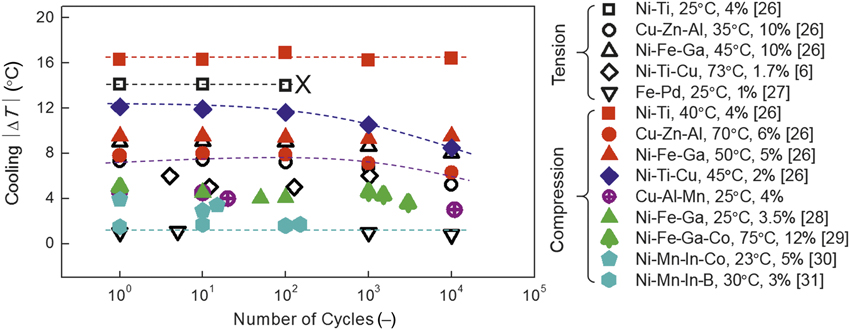
Extending fatigue life of materials may also be achieved by implementing mechanically robust SMA materials and by applying smaller strains.Reference Ashby, Shercliff and Cebon13,Reference Pelton25 The endurance limit—a stress amplitude below which failure is avoided—has a positive correlation with the ultimate strength.Reference Ashby, Shercliff and Cebon13 Figure 5Reference Wu, Ertekin and Sehitoglu26–Reference Yang, Cong, Sun, Nie and Wang31 shows a summary of elastocaloric materials and their performance indicating that high-strength materials such as Ni-Ti with transformation stress of ≈650 MPa (versus ≈150 MPa in Cu-Zn-Al) can produce stable elastocaloric cooling over 10,000 cycles under compression without degradation. High-strength materials can thus have long fatigue life and the potential for stable elastocaloric cooling. If one envisions a 10-year operation of a commercial elastocaloric cooling device such as an elastocaloric air conditioner, this would require about a million cycles of SMAs under 0.05 Hz operation, assuming usage for half a day for six months in a year. The fatigue requirement of SMAs would further become less stringent if there is lower frequency of device. Decreasing applied strain can lead to extended fatigue life,Reference Pelton25,Reference Robertson, Pelton and Ritchie32 and from Figure 5, a small amplitude of strain such as 1.0% in Fe–Pd (versus 6.0% in Cu-Zn-Al) appears to help maintain elastocaloric cooling cycles despite concomitantly reduced cooling ΔT. As previously discussed, cyclic tension can lead to fracturing in a relatively smaller number of cycles, as marked by the X for Ni–Ti in Figure 5.
Evolution of elastocaloric cooling performance of different materials over cycles of operation. Absolute value of cooling ∆T versus cycles in different classes of shape-memory alloys. Unfilled symbols are for tensile mode, and solid symbols are for compressive mode. A crossmark indicates the cycle where failure took place, while no crossmark means there was no failure at the end of cycling. The test temperature, T test, and the strain amplitude, Δε, of each material are displayed in the legend.Reference Bechtold, Chluba, De Miranda and Quandt6,Reference Wu, Ertekin and Sehitoglu26–Reference Yang, Cong, Sun, Nie and Wang31

Concluding remarks
Compression-based elastocaloric cooling enables extended operation due to prolonged fatigue lifetime in SMAs compared to tension-based cooling. This is due to the unidirectional nature of stress-induced martensitic transformation and the tension–compression asymmetry in superelasticity inherent to SMAs. Employing mechanically strong alloys and applying low strains are also good strategies to facilitate long-term operation of elastocaloric cooling materials. Compression-based elastocaloric cooling has been successfully implemented in the development of elastocaloric prototype systems. Based on compression-based designs, exploration of high-capacity elastocaloric materials for extended cooling and optimization of systems with improved heat transfer can competitively advance elastocaloric cooling into the arena of practical cooling technologies.
Acknowledgments
This work was supported by the Caloric Cooling Consortium, CaloriCool. The Consortium is a member of the US Department of Energy (DOE) Energy Materials Network, and is supported by the Advanced Manufacturing Office of the Office of Energy Efficiency & Renewable Energy of the DOE. The work at Ames Laboratory is supported by the Division of Materials Science and Engineering of the Basic Energy Sciences Programs of the Office of Science of the US Department of Energy under Contract No. DE-AC02–07CH11358 with Iowa State University. Advanced Research Projects Agency-Energy (ARPA-E, DOE) supported the development of elastocaloric systems at the University of Maryland under Grant No. ARPA-E DEAR0000131. S.Q. was supported by the National Natural Science Foundation of China under Grant No. 51606140.

Huilong Hou is a postdoctoral research associate in the Department of Materials Science and Engineering at the University of Maryland. He received his PhD degree in engineering science and mechanics from The Pennsylvania State University in 2015. His current research focuses on exploring and tailoring shape-memory alloys for elastocaloric cooling and implementing advanced fabrication techniques for thin films and bulk materials. He is a member of The Minerals, Metals and Materials Society and the American Vacuum Society. Hou can be reached by email at hhou@umd.edu.

Jun Cui is an associate professor at Iowa State University and a senior scientist at Ames Laboratory. He received his PhD degree in solid mechanics from the University of Minnesota in 2002. His research interests include shape-memory alloys, elasto- and magnetocaloric materials, and permanent and soft magnetic materials. He has authored or co-authored 45 publications and holds 10 patents. Cui can be reached by email at cuijun@iastate.edu.

Suxin Qian is an assistant professor in the Department of Refrigeration and Cryogenic Engineering at Xi’an Jiaotong University, China. He received his PhD degree from the Department of Mechanical Engineering at the University of Maryland in 2015. His current research interests focus on non-vapor compression cooling and heat-pump technologies. He is a junior member of the International Institute of Refrigeration. Qian can be reached by email at qiansuxin@mail.xjtu.edu.cn.

David Catalini is a doctoral candidate at the University of Maryland. He received his BS degree in materials engineering from Universidad Nacional de Mar del Plata, Argentina, and his MS degree in mechanical engineering from the University of South Carolina. He is also a materials engineer in the Energy and Environment Directorate at Pacific Northwest National Laboratory. His research focuses on development of elastocaloric cooling systems. Catalini can be reached by email at catalini@umd.edu.

Yunho Hwang is the associate director of the Center for Environmental Energy Engineering and a research professor at the University of Maryland. He earned his PhD degree in mechanical engineering from the University of Maryland in 1997. His research focuses on energy-conversion systems and energy efficiency by developing innovative processes and improving existing processes. He has authored or co-authored 260 publications, 10 patents, and co-authored two books. He is an ASME Fellow and an editor for the journal Energy. Hwang can be reached by email at yhhwang@umd.edu.

Reinhard Radermacher is a professor of mechanical engineering and director of the Center for Environmental Energy Engineering at the University of Maryland. He received his PhD degree in physics from Technische Universität München, Germany. He conducts research in heat-transfer and working fluids for energy-conversion systems. He has authored or co-authored 400 publications, 12 patents, and three books. His awards include the J&E Hall Gold Medal and the Gustav Lorentzen Medal. He is an American Society of Heating, Refrigeration, and Air Conditioning Engineers Fellow. He serves as editor-in-chief of the journal Science and Technology for the Built Environment. Radermacher can be reached by email at raderm@umd.edu.

Ichiro Takeuchi is a professor of materials science and engineering and an affiliate professor of physics at the University of Maryland. He obtained his PhD degree in physics at the University of Maryland in 1996. He was a postdoctoral research fellow at the Lawrence Berkeley National Laboratory from 1996 to 1999. His research focuses on combinatorial materials science, multilayer thin-film devices, and elastocaloric cooling. He also serves as the chief technology officer of Maryland Energy and Sensor Technologies, LLC. Takeuchi can be reached by email at takeuchi@umd.edu.