I. INTRODUCTION
Microstrip multiband bandpass filters (BPFs) with high performance are essential components in the design of multiband communication systems. In tri-band transceivers, the tri-band BPFs working at triple frequency bands are extensively investigated and various design approaches have been proposed. The tri-band BPFs can be constructed using open-circuited stub-loaded resonators [Reference Zhang, Xue and Hu1, Reference Chen, Weng and Chang2], and short-circuited stub-loaded resonators [Reference Zhang and Zhu3, Reference Sun, Su, Deng, Wu and Liang4]. However, the overall size is not very compact. Another widely used method for designing a tri-band filter is making use of multimode resonators, such as multimode stepped-impedance resonator (SIR) [Reference Liu5, Reference Sarkar, Ghatak, Pal and Poddar6]. In [Reference Lai, Tang, Zhan, Cao, Wu and Zhang7], transversal structures are applied to design tri-band filters. Owing to the large number of resonators, the size of the tri-band filters is relatively large. Tri-band filters can also be constructed using a stub-loaded resonator with a defected ground structure (DGS) resonator [Reference Lai, Liang, Di and Wu8, Reference Kumar and Machavaram9]. However, the DGS structure causes a complex integration in packaging. Other tri-band filters are typically realized using square ring resonators [Reference Doan, Che and Feng10], E-type resonators [Reference Fan, Li and Gong11], and Hilbert-fork resonators [Reference Jankovic, Geschke and Bengin12]. Nevertheless, the flexible design of tri-band filters with compact size and good performance still remains a challenge.
To minimize the overall size further, a compact tri-band filter with multiple transmission zeros and controllable bandwidths is implemented in this paper. The short-circuited SIR is introduced to construct tri-band BPF. The fundamental even-mode is utilized to determine the center frequency of the first passband, and the odd-mode is utilized to determine the center frequency of the second passband. The third resonant frequency, which is the first spurious resonant frequency, is applied to determine the center frequency of the third passband. In this way, the whole center frequencies of the triple passbands can be controlled. The mode-splitting technique is applied by combining two SIRs with electrical coupling and then one mode will be split into two modes. The split two modes generate one passband and the bandwidths can be controlled by the electrical coupling strength. The 0° feed structure is applied in the filter design and the advantage is that two extra transmission zeros are created in the stopband, while the passband response remains unchanged, resulting in high isolation and selectivity [Reference Tsai, Lee and Tsai13].
II. DESIGN PROCEDURE OF THE TRI-BAND BPF
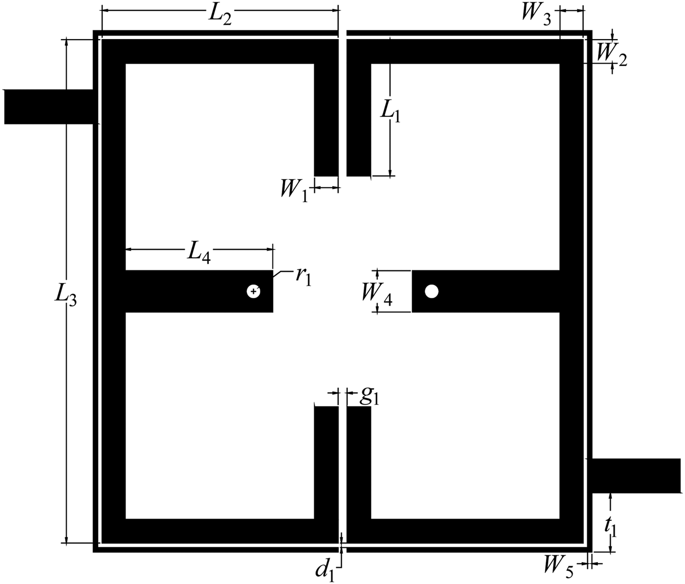
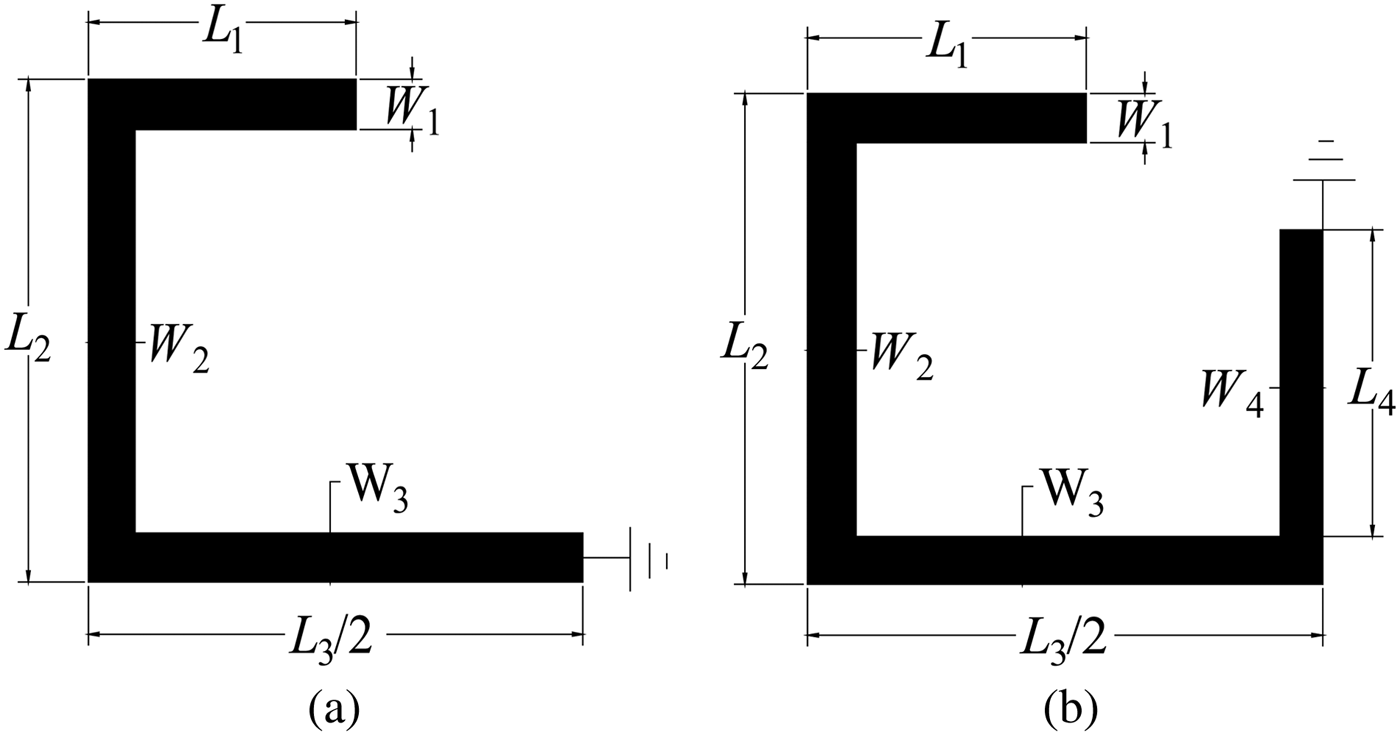
The layout of the proposed tri-band BPF is shown in Fig. 1. This tri-band filter is composed of two multimode SIRs and a 0° feed network. This multimode SIR is denoted by lengths (L 1, L 2, L 3) and widths (W 1, W 2, W 3) with a short-circuited stub perturbation with length L 4 and width W 4 at the center plane. As the SIR is symmetrical, the even–odd-mode method can be applied to explain its equivalent circuits, as shown in Fig. 2. The odd-mode SIR is identical to a quarter-wavelength SIR since a virtual ground exists in the symmetry plane. For the even-mode SIR, the virtual ground is replaced by a virtual open circuit. There is no coupling between the even- and odd-modes and the stub perturbations do not affect the odd-mode. The odd-mode resonant frequency f odd and even-mode resonant frequency f even can be determined by the line length L odd and L even, respectively, which can be expressed as
 $${L_{odd}}=4{L_1}+4{L_2}+2{L_3}\comma$$
 $${L_{even}}=4{L_1}+4{L_2}+2{L_3}+4{L_4}.$$
Layout of the proposed tri-band filter.

Odd-mode (a) and even-mode (b) equivalent circuits of the proposed SIR.
Then the first resonant frequency f even and the second resonant frequency f odd can be expressed as
 $${f_{even}}=\displaystyle{c \over {\left({4{L_1}+4{L_2}+2{L_3}+4{L_4}} \right)\sqrt {{\varepsilon _{eff}}} }}\comma$$
 $${f_{odd}}=\displaystyle{c \over {\left({4{L_1}+4{L_2}+2{L_3}} \right)\sqrt {{\varepsilon _{eff}}} }}.$$
The line length L 4 does not affect the odd-mode resonant frequency because of the virtual ground that forms in the symmetry plane, whereas the even-mode is directly dependent on the line length L 4, as shown in Fig. 3(a). The line lengths L 1, L 2, and L 3 affect both the even- and odd-mode resonant frequencies. Fig. 3(b) shows that the even- and odd-mode resonant frequencies vary with L 2.
Variation of even–odd-mode resonant frequency on L 4 (a) and L 2 (b).
The first step is to determine the center frequencies of the triple passbands. The center frequencies of the first and second passbands are determined by f even and f odd, respectively. The center frequency f 3 of the third passband is determined by the third resonant frequency, which naturally occurs at 3f even. Based on the SIR, the center frequency f 3 can be adjusted by the impedance ratio of the SIR. Therefore, the center frequencies of the triple passbands can be adjusted to the required values.
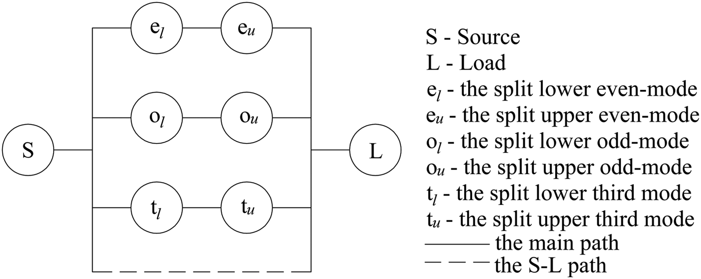
The second step is to obtain the required bandwidths for the triple passbands. The mode-splitting technique is applied by combining two multimode SIRs with the electrical coupling. Therefore, the odd-mode, even-mode, and the third mode will split into two modes, respectively, which can be shown in Fig. 4. The split two modes are applied to generate one passband and the bandwidths can be controlled by the electrical coupling strength. Fig. 5 shows the coupling scheme of the proposed tri-band BPF. The coupling strength of the electrical coupling can be adjusted by the gap distance g 1, as shown in Fig. 6. It is shown that the electrical coupling strength is relatively large when the gap distance g 1 is small, whereas the electrical coupling strength is reduced sharply when the gap distance g 1 is increased. The coupling coefficients K i,j, and the external quality factor Q e can be expressed as
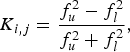 $${K_{i\comma j}}=\displaystyle{{f_u^2 - f_l^2 } \over {f_u^2+f_l^2 }}\comma$$
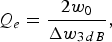 $${Q_e}=\displaystyle{{2{w_0}} \over {\Delta {w_{3\, dB}}}}\comma$$
where f u and f l are defined as the upper and lower resonant frequencies of the two split resonant modes, w 0 is the resonant frequency, and the Δw 3 dB is the 3 dB bandwidth. It is shown that a wider bandwidth needs a smaller external quality factor Q e. A smaller coupling gap and a narrower line result in a stronger coupling or smaller external quality factor Q e. However, the Q e cannot be too small, because the coupling strength of the external feed network, namely the coupling microstrip line, is limited. Therefore, there is a tradeoff between the bandwidth and external coupling strength. Fig. 7 shows the bandwidths varying with the gap distance g 1. To introduce multiple transmission zeros, the 0° feed network is applied. Owing to the 0° feed structure, one pair of transmission zeros locate at each side of all the triple passbands, resulting in high isolation and selectivity. The external quality factor Q e is dominated by the tapped location t 1. The desired tri-band frequency response can be obtained by shifting the location of t 1 to induce a suitable Q e for the bandwidths of f even, f odd, and f 3. The t 1 is chosen to be 2 mm, leading the Q e to be in turn 23, 16, 37 at 1.8, 2.4, 5.8 GHz, respectively. Till now, the initial dimensions of the tri-band filter have been obtained. The remained work is to get desirable performance of each passband by parameters tuning and optimization using three-dimensional (3D) simulation software HFSS.
The mode splitting by electrical coupling.
The coupling scheme of the proposed tri-band BPF.
The coupling coefficients vary with the gap distance g 1.
The bandwidths vary with the gap distance g 1.
III. EXPERIMENTAL RESULTS
Based on the analysis expressed in the above section, a tri-band BPF is designed and fabricated. A photograph of the fabricated tri-band BPF is shown in Fig. 8. The overall size of the tri-band BPF is 16.3 mm × 17 mm. The main dimensions are given as follows: L 1 = 4.6, L 2 = 8, L 3 = 17, L 4 = 5, W 1 = 0.8, W 2 = 0.8, W 3 = 0.78, W 4 = 1.4, and W 5 = 0.15 mm; and r 1 = 0.25, d 1 = 0.15, t 1 = 2, and g 1 = 0.3 mm. The substrate is Taconic RF-35 with a relative dielectric constant of 3.5, substrate thickness of 0.508 mm, copper thickness of 0.035 mm, and loss tangent of 0.0018.
A photograph of the fabricated tri-band BPF.
The first passband is centered at 1.8 GHz for 4 G LTE application and 3 dB fractional bandwidth is 8.9%. The simulated minimum insertion loss and return loss are 0.8 and 20 dB, respectively, whereas the measured minimum insertion loss and return loss are 1.5 and 15 dB, respectively. The second passband is located at 2.4 GHz for wireless local area network (WLAN) application and the 3 dB fractional bandwidth is 12.5%. The simulated minimum insertion loss and return loss are 0.7 and 31 dB, respectively, whereas the measured minimum insertion loss and return loss are 0.9 and 23 dB, respectively. The third passband has the center frequency of 5.8 GHz for WLAN application and the 3 dB fractional bandwidth is 5.3%. The simulated minimum insertion loss and return loss are 1.5 and 16 dB, respectively, whereas the measured minimum insertion loss and return loss are 2.9 and 19 dB, respectively. Owing to the 0° feed structure, one pair of transmission zeros locate at each side of all the triple passbands, resulting in high isolation and selectivity. However, the transmission zeros located at the same stopband region have overlapped. Therefore, at least one transmission zero can be obtained at each stopband region. The isolation between the first passband and the second passband is 40 dB, whereas the isolation between the second passband and the third passband is more than 40 dB. The values of group delay at the center frequencies of the three passbands are 3.5, 2, and 2.5 ns, respectively. The simulated and measured results of the fabricated tri-band BPF are shown in Fig. 9. The measured results are in good agreement with the simulated ones. The larger insertion loss and other discrepancy might be because of the unexpected tolerance of fabrication. Table 1 shows some reported performances of tri-band BPFs in recent years for comparison.
The simulated and measured results of the fabricated tri-band BPF.
Comparisons with other reported tri-band BPFs (λ g is the guided wavelength at f 1).
IV. CONCLUSION
A compact tri-band BPF using two multimode SIRs and 0° feed network is proposed in this paper. The center frequencies of the triple passbands can be independently tuned to desired values by controlling the corresponding resonator dimensions. The mode-splitting technique is applied by combining two SIRs with electrical coupling and the bandwidths can be controlled by the electrical coupling strength. Owing to the 0° feed network, multiple transmission zeros have been obtained, resulting in high isolation and selectivity. The design procedures of the tri-band BPF have been described in detail. The simulated and measured results of the tri-band BPF are given to verify the proposed principle. It is shown that the proposed tri-band BPF has the advantages of compact size, good performance, and flexible design, which make it attractive for multiband wireless communication.
 Qun Li received his B.E. degree from Southwest Petroleum University, Chengdu, China, in 2012 and now is studying for a Ph.D. degree in Electromagnetics and Microwave Technology from the University of Electronic Science and Technology of China (UESTC), Chengdu, China. His research interests include electromagnetic theory and microwave circuits and systems.
 Yong-Hong Zhang received his B.S., M.S., and Ph.D. degrees from the University of Electronic Science and Technology of China (UESTC), Chengdu, China, in 1992, 1995, and 2001, respectively. From 1995 to 2002, he was a Teacher with the UESTC. In 2002, he joined the Electronic Engineering Department, Tsinghua University, Beijing, China, as a Doctoral Fellow. In 2004, he rejoined the UESTC. His research interests are in the area of microwave and millimeter-wave technology and applications.
 Xin Feng received his B.E. degree from Southwest Jiao-tong University, Chengdu, China in 2009. In 2010, he went on studying in the University of Electronic Science and Technology of China (UESTC), where he won the first grade of scholarship and was directly admitted as a Ph.D. candidate. He is currently studying in the EHF Key Laboratory of Fundamental Science in EE school of UESTC. His research interests include microwave and millimeter wave circuit and system.
Yong Fan received his B.E. degree from the Nanjing University of Science and Technology, Nanjing, Jiangsu, China, in 1985, and the M.S. degree from the University of Electronic Science and Technology of China Chengdu, Sichuan China, in 1992. From 1985 to 1989, he was interested in microwave-integrated circuits. Since 1989, He dedicated himself to research and teaching on the subjects of Electromagnetic Fields and Microwave Techniques for many years. His main research fields are as follows: electromagnetic theory, millimeter-wave communication, millimeter-wave, Terahertz Circuits, etc. Besides, he was interested in other subjects, including Broadband Wireless Access, automobile anti-collision, intelligent transportation, etc.