I. INTRODUCTION
High hardness, low friction coefficient, chemical inertness, biocompatibility, and wear resistance are good properties associated with diamond-like carbon (DLC) films. To further improve the properties, carbon nanotubes (CNTs) have been doped into DLC films. The elastic modulus of CNTs is at the order 1–3 TPa,Reference Salvetat-Delmotte and Rubio1 which is 1,000 times higher than high-strength steel alloys.Reference Saether, Frankland and Pipes2 They also exhibit superior electrical and thermal properties.Reference Mauron, Emmenegger, Zuttel, Nutzenadel, Sudan and Schlapbach3 Research on CNTs doping is popular in the field of polymer composites for its effectiveness in improving the electrical, mechanical, and thermal properties,Reference Valentini, Biagiotti, Kenny and Santucci4 as well as in the field of metal matrix composites.Reference Chen, Tu, Wang, Gan, Xu and Zhang5, Reference Zhong, Cong and Hou6 The matrix can be either soft or ductile. For hard matrix like ceramics, many new strengthening mechanisms such as CNT collapse and shear banding occur.Reference Xia, Riester, Curtin, Li, Sheldon, Liang, Chang and Xu7 Recently, CNTs have been included in DLC films to increase toughness,Reference Kinoshita, Ippei, Sakai and Ohmae8 reduce friction coefficient,Reference Wei, Wang, Tai, Ting and Chang9 or lower residual stress.Reference Hu, Chen and Zhang10 However, the discrepancy in hardness of CNTs/DLC composites seems to depend on CNT orientations. For vertically grown CNTs-doped DLC films, the overall hardness is reduced compared to undoped ones,Reference Kinoshita, Ippei, Sakai and Ohmae8 while for horizontal dispersed CNTs-doped DLC films, the overall hardness is increased.Reference Wei, Wang, Tai, Ting and Chang9 This phenomenon poses the question of exactly how the hardness in CNTs-doped DLC films is affected by CNT orientation. In this work, we address this question by carrying out a nanoindentation to calculate the hardness of CNTs-doped DLC films on silicon substrates via three-dimensional (3D) and two-dimensional (2D) finite element analysis. The effects of modulus anisotropy, CNT orientation, interface strength, and indentation size effect (ISE) on hardness and associated mechanisms are questions to be addressed.
II. THE THEORY OF NANOINDENTATION HARDNESS
Indentation has been an effective tool to measure the hardness and elastic modulus of a material. The hardness measurements of the Knoop, Vickers, and Rockwell tests are derivations from indentation. Nanoindentation applies similar principles except that the indentation depth is measured in nanometers rather than in microns. Nanoindentation relies on continuous measurements of indentation depths with increased loading and elastic unloading. Mechanical properties like hardness and elastic modulus can be extracted from the measurements. The theory of nanoindentation is based on the contact depth, h c, which is a function of indentation depth, the applied load, and the contact stiffness as followsReference Oliver and Pharr11:
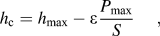
where h max is the maximum indentation depth, P max is the maximum applied load, S is the contact stiffness, and ε is a geometry correction factor and for Berkovich indenter ε = 0.75. The projected area A c of the actual contact area is a function of h c and for a perfect Berkovich indenter, A c is given by

Hardness is the mean pressure that a material can support under load; and in nanoindentation, it is calculated by dividing the applied load F with the contact area A c as

Note that this hardness is defined by using the projected area of the contact under load. The projected contact area is calculated directly from the finite element analysis.
III. FINITE ELEMENT ANALYSIS
In this study, the elastic property for CNTs is taken as transverse isotropy.Reference Xia, Riester, Curtin, Li, Sheldon, Liang, Chang and Xu7 A full description of a transversely isotropic material requires five material constants. To model such material, a 3D nanoindentation process is necessary. In the process, the 3D rigid indenter is used and the load is applied along the axis of the indenter, and the load symmetry is the same as the geometric axis. Due to symmetry, a 3D model can be defined by one-sixth of the entire system. The specimen is modeled with 8-node linear brick, reduced integration, hourglass control elements (C3D8R element type). Due to axisymmetry, the results of a rigid indenter should be similar to those of a deformable indenter.
To investigate the effect of modulus anisotropy in CNTs, we also perform a 2D axisymmetric analysis. An equivalent conical indenter with a semiapical angle of θ = 70.3° is used. This system has geometric and loading symmetry around the axis of the indenter. The specimen is modeled with 4-node axisymmetric quadrilateral, reduced integration, hourglass control elements (CAX4R element type). A high mesh refinement is used to model the large deformation area. The elements in the film are reduced in height to detect the behavior of the zone with greater accuracy. The total number of elements was generally 30,000–40,000. The finite element analysis was implemented by a commercial software ABAQUS (version 6.8.1; ABAQUS Inc., Pawtucket, RI). The ratio of thickness of the film and the substrate is 1:1,000 and the film thickness is 1,000 nm.
For simplicity, the CNTs are modeled as cylinders in 3D and rectangles in 2D. It is well known that CNT is a thin shell structure and cylinder modeling is regarding CNTs as fiber rather than tubes. The distribution of CNTs is along the interface between the DLC film and the substrate. This is to simulate the experiments for vertically grown CNTs/DLC/SiReference Kinoshita, Ippei, Sakai and Ohmae8 and horizontally deposited CNTs/DLC/Si.Reference Wei, Wang, Tai, Ting and Chang9 Unlike CNTs/polymer where CNTs are evenly distributed in the matrix, CNT distribution in our modeling is along the interface. The content of CNTs is based on the volume fraction in 3D and area fraction in 2D of CNTs over DLC films. Based on the experiments, the volume (area) fraction of CNTs is less than 1%. As for the effect of CNT orientation on hardness, two additional orientations such as 45° and random orientation are used to compare with those in vertical and horizontal orientations.
As for the material properties, the diamond tip is modeled with E = 1140 GPa and ν = 0.07. The constitutive law is elastoplastic for DLC films and is elastic for CNTs. The elastic behavior in CNTs is modeled by a linear law with five constants in the 3D case and with two constants in the 2D case. Young’s modulus and Poisson’s ratio for DLC is E = 120 GPa and ν = 0.25. As for plastic behavior, the von Mises yield criterion is used with the initial flow stress σ 0 = 4610 MPa. After yield, the power law hardening is used and expressed as follows:

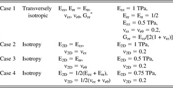
where K = 120 GPa and n = 0.55 for DLC. The elastic constants of CNT used in the 3D and the 2D simulation are summarized in Table I.
The constitutive law and material properties for transversely isotropic (3D), isotropic (2D vertical), isotropic (2D horizontal), and isotropic (2D 45 degree).

* z: vertical direction, t: transverse plane, r: radial (horizontal) direction in transverse plane
IV. RESULTS AND DISCUSSION
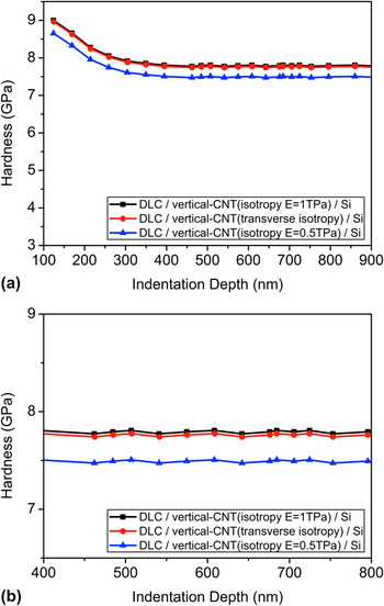
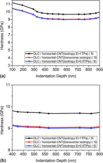
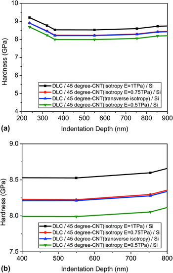
For transversely isotropic inclusions like CNTs, the modeling is 3D in nature. However, a comparison with the 2D isotropic counterpart demonstrates how the degree of modulus anisotropy affects the overall hardness in dilute CNTs/DLC/Si. Therefore, 3D simulations with volume fraction 0.17% with transversely isotropic CNTs/DLC are compared with the 2D modeling with the same fraction and isotropic CNTs/DLC. The results for overall hardness in vertical CNTs-doped DLC for 2D isotropy with E = 1 TPa, 3D transversely isotropic, and 2D isotropy with E = 0.5 TPa are shown in Fig. 1. Two-dimensional isotropy with E = 1 TPa means that in 2D simulation the elastic modulus of CNTs is taken as isotropic material with Young’s modulus having the same value as that in the indentation direction (E = 1 TPa, vertical direction, z-axis) in a 3D transverse isotropy case. Similarly, 2D isotropy with E = 0.5 TPa means that Young’s modulus is taken to be the same value as that in the transversely isotropic plane (E = 0.5 TPa, horizontal direction, r-axis) in a 3D case. Note that in the 3D transversely isotropic model, Young’s modulus in the long axis is twice as large as that in the transversely isotropic plane. The results in Fig. 1(a) show that for vertical CNTs-doped small fraction DLC films, the 2D vertical (E = 1 TPa) result is very close to the 3D transversely isotropic case [as shown in Fig. 1(b)]. Similarly, for horizontal CNTs-doped DLC films [Fig. 2(a)], the hardness in 2D horizontal (E = 0.5 TPa) is very close to the 3D transversely isotropic counterpart [as shown in Fig. 2(b)]. Figure 3(a) shows the hardness at 45° CNT orientation. The 3D result is close to the 2D counterpart as long as the elastic modulus is taken as the arithmetic mean of the long and the short axes (E = 0.75 TPa) as shown in Fig. 3(b). All these results imply that for transversely isotropic dilute inclusions, the inclusion of modulus anisotropy does not seem to be critical in terms of hardness. Therefore, for dilute CNTs concentration (0.17%), the 3D calculation can be modeled by a 2D isotropic case as long as the elastic modulus in 2D is chosen to be in accord with that in the loading axis in 3D transversely isotropic inclusions. For 45° orientation, the rule of arithmetic mean of the modulus in both axes is applied. Therefore, in these particular transversely isotropic inclusions, the 2D finite element analysis can be used to replace 3D analysis and simplify the analysis.
The hardness of (a) 0.17%, vertical carbon nanotubes (CNTs)-doped diamond-like carbon (DLC) films by three-dimensional (3D) and two-dimensional (2D) finite element formulation and (b) zoom-in picture.

The hardness of (a) 0.17%, horizontal CNTs-doped DLC films with by 3D and 2D finite element formulation and (b) zoom-in picture.

The hardness of (a) 0.17%, 45° CNTs-doped DLC films with by 3D and 2D finite element formulation and (b) zoom-in picture.

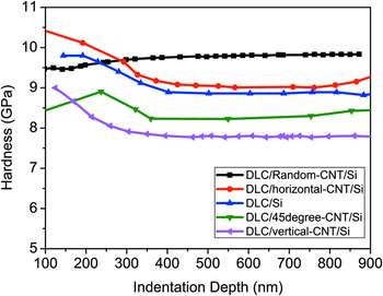
Based on the results shown in the previous section, the effect of different CNT orientation is examined by a simplified 2D analysis. The hardness of vertical, horizontal, 45°, and random orientation CNTs/DLC is compared with that in undoped DLC films as shown in Fig. 4. For random orientation, the elastic modulus is taken as follows:

The hardness of 0.17%, different orientation CNTs/DLC/Si versus undoped DLC films.

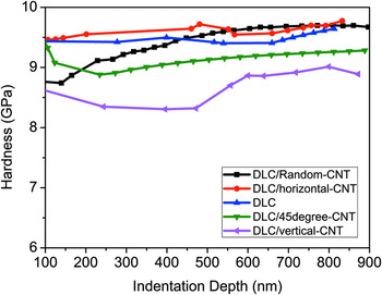
where θ is the angle between the indentation axis and the CNTs. This formula can represent all CNT orientations, e.g., for vertical orientation the angle is zero and E = 1TPa, and for horizontal orientation, θ = π/2 and E = 0.5 TPa. In all orientations, for indentation depth less than 300 nm, the horizontal CNTs have larger hardness compared to random orientation and undoped DLC films. When the indentation exceeds 300 nm, random orientation CNTs have the greatest hardness among all. The hardness of other orientations such as 45° or vertical direction is less than undoped DLC films. These results are in agreement with the experimental resultsReference Kinoshita, Ippei, Sakai and Ohmae8, Reference Wei, Wang, Tai, Ting and Chang9 which show that the hardness for vertical CNTs/DLC/Si is smaller than that in horizontal CNTs/DLC/Si. For dilute CNTs contents, this analysis predicts the similar trend. To further investigate the effect of different CNT orientations on the hardness without substrate effect, we perform a similar analysis without silicon substrate and the results are shown in Fig. 5. For shallow indentation depth (less than 400 nm), the hardness of horizontal CNTs is greater, but the random orientation has the largest hardness in greater indentation depth. The hardness order in different CNTs/DLC is as follows: random > horizontal > undoped > 45° > vertical which is in agreement with CNTs/DLC/Si. This indicates that the substrate effect does not affect the overall hardness.
The hardness of 0.17%, different orientation CNTs/DLC versus undoped DLC films.

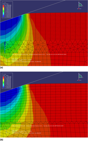
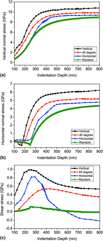
One might ask why a stiffer vertical CNTs (E = 1 TPa) doped DLC film results in smaller hardness than a less stiff horizontal CNTs (E = 0.5 TPa) doped DLC film. Two possible mechanisms are proposed. The first is based on the sign and magnitude of the stress. Figures 6(a) and 6(b) are shear stress distributions of vertical CNTs/DLC/Si and horizontal CNTs/DLC/Si, respectively. For vertical CNTs-doped DLC films, the CNTs are aligned with the indentation loading. Therefore, vertical CNTs withstand more stress than horizontal CNTs. The stress variation versus indentation depth is further illustrated in Fig. 7 where the stress components in different orientations (vertical, horizontal, 45°, and random) are demonstrated. For normal stress in vertical and horizontal directions, the stress in vertical CNTs-doped DLC films is highest among all orientations as shown in Figs. 7(a) and 7(b), respectively. For shear stress, there is a decline in shear stress for all orientations after the indentation depth exceeds 30% of the film thickness with the biggest decrease in horizontal direction [as shown in Fig. 7(c)]. Not only is the magnitude of the shear stress for horizontal and random CNTs smaller, but the sign of the stress in horizontal orientation changes from positive to negative. Recently, we have shown that smaller positive shear stress and larger negative shear stress lead to a higher hardness.Reference Wei and Yang12 Therefore, the lower stress in horizontal and random CNTs/DLC increases the hardness and this might be the reason why the hardness in these orientations is higher.
The stress distribution for 0.17% (a) vertical CNTs doped DLC films and (b) horizontal CNTs doped DLC films.

The stress variation with indentation depth of different orientation CNTs doped DLC films for (a) vertical stress, (b) horizontal stress, and (c) shear stress.

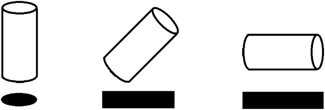
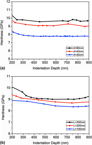
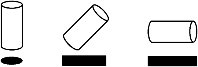
The other possible hardness enhancement mechanism is the effective projected area of different CNT orientations. The idea of projected area is shown schematically in Fig. 8 for vertical, 45°, and horizontal CNTs. For high aspect ratio CNTs, the effective projected area of vertical CNTs is very small compared to that of horizontal CNTs. Even though horizontal CNTs (E = 0.5 TPa) have lower modulus along the indentation direction than horizontal CNTs (E = 1 TPa), the larger effective area in the former will actually lead to higher hardness. This argument is further verified by increasing the diameter of vertical CNTs (d) or the length (L) of horizontal CNTs without changing the modulus. For same volume fraction, vertical CNTs with a larger diameter or horizontal CNTs with longer length will increase the effective area in the single CNT but decrease the total number of CNTs. Figure 9(a) compares the hardness in vertical CNTs-doped DLC films with varying diameters with the same length under the same CNT concentration. For vertical orientation, a larger diameter but with a smaller number of CNTs seems to be more effective in hardness enhancement than those with a smaller diameter but with more quantity. Similar results are shown in Fig. 9(b) for horizontal CNTs with different lengths but the same diameter. It is worth mentioning that hardness difference due to dimensional change is not proportional to diameter change or length change. Therefore, it is not a pure geometrical effect. Other effects like stress might be responsible for such nonlinearity. For random orientation, the coupling and interaction effects among each CNT might be the reason why random CNTs have the best hardness enhancement among all orientations. For dilute CNT concentration, different stress distribution and varying effective projected area under different CNT orientations are the underlying mechanisms for hardness enhancement.
The projected area of vertical, 45°, and horizontal CNTs.
Hardness trends for different sizes of CNTs due to (a) diameter change and (b) length change.

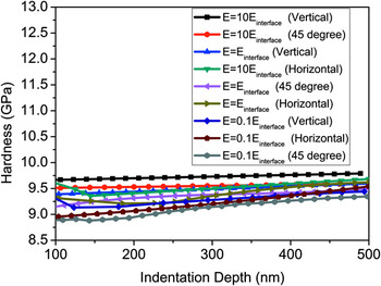
There are certain issues that might affect the hardness for CNTs/DLC. One is the interface strength between CNTs and DLC films. Even though DLC films are amorphous in nature, therefore the lattice misfit along different CNT orientation might not occur; it is still important to probe the role of interface strength in overall hardness. We model the interface between CNTs and DLC films by adding a very thin layer (4 nm) to wrap the CNT as the interface.Reference Cai and Bangert13 The strength of the interface is represented by the elastic modulus of the interface. For normal interface strength, the elastic modulus is taken as the average value of the elastic modulus of CNTs and DLC films. The strong and weak interface strength is 10 times and 10% of the normal interface strength, respectively. The effect of the interface strength along different CNT orientations is shown in Fig. 10 for 0.34% volume fraction. Unlike previous results, the strong interface effect of vertical and 45° CNTs has better hardness enhancement than that in horizontal CNTs. This is due to the fact that for vertical CNTs, the indentation direction is along the long axis where the interface strength is critical. As for horizontal CNTs, the indentation direction is along the short axis and the interface strength is not as critical.
The effect of different interface strength in different CNT orientations.

The other important issue in hardness measurement is the indentation size effect (ISE),Reference Sangwal14–Reference Ebisu and Horibe17 which indicates that the surface properties dominate at low indentation load and that bulk effect is prominent when the indentation depth increases. For amorphous DLC films, strain gradient plasticityReference Ma and Clarke18, Reference Nix and Gao19 mechanism cannot promote ISE as it in crystalline materials and ISE is not expected to be significant. However, it is interesting to probe the relationship between different CNTs orientations and ISE. To investigate ISE, we use Meyer’s lawReference Sangwal14

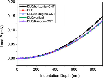
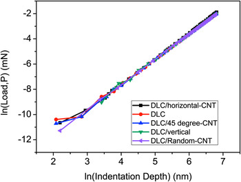
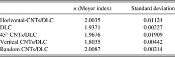
where P is the applied load, A is a constant, h is the indentation depth, and the exponent n is the Meyer index. For normal ISE, the exponent n < 2 and for reverse ISE n > 2. Fig. 11 exhibits the load–indentation depth curves for vertical, 45°, horizontal, random CNTs/DLC and DLC only. Except for horizontal CNTs/DLC, all the other curves are similar in P–h curves. To further quantify the value of n, we take natural log plot of Eq. (6) and the results are shown in Fig. 12 and tabulated in Table II. For horizontal and random CNTs, the Meyer’s index is close to two, while for other orientations (vertical, 45°) and undoped DLC, the Meyer’s index is less than two with the vertical CNTs having the lowest value. Therefore, for undoped DLC, vertical CNTs/DLC, and 45° CNTs/DLC films, there is an ISE; while for horizontal and random CNTs/DLC films, the ISE in not significant.
The load-indentation curves for different CNT orientations/DLC and undoped DLC films.

The nature log plot of Meyer’s law for different CNT orientations DLC films.

The Meyer index for different carbon nanotube (CNT) orientations/diamond-like carbon (DLC) films.

V. CONCLUSIONS
Numerical simulations of different orientation CNTs-doped DLC are presented via 3D and 2D finite element analysis. The results show that for dilute CNT concentration (0.17%), the hardness obtained from a 2D finite element analysis is similar to a 3D analysis as long as the elastic modulus of the 2D analysis is properly chosen. The hardness is affected by the orientation of CNTs and the mechanisms are varying stress magnitude and difference in the projected area. The negative shear stress in horizontal CNTs-doped DLC films increases the hardness, while the positive shear stress in vertical CNTs reduces the hardness. The vertical CNTs have lower overall hardness than horizontal CNTs due to the smaller effective area. For hardness enhancement, the interface strength is more critical in vertical CNTs than that in horizontal CNTs, and this is due to the longer interfacial region. The ISE is shown in certain CNT orientation (vertical and 45°) and is not prominent in horizontal and random orientations. These findings should apply to other matrix material e.g., CNTs-doped polymer composites. It seems that the orientation of CNTs is more critical in hardness enhancement than the number of CNTs for dilute concentration. More experiments are needed to validate these arguments.
ACKNOWLEDGMENT
Financial support provided by the National Science Council of ROC under grant NSC-99-2221-E-036-005 is gratefully acknowledged.