I. INTRODUCTION
Organic/inorganic nanocomposites possess the advantage of the two original compounds by making full use of the synergistic effect between the organic and inorganic components. The nanosized dispersed inorganic phase largely enhances the interfacial interactions, which gives rigidity and good stability. While the presence of the organic phase gives a certain excellent properties of organic material, such as light weight, flexibility, ductility, and impact strength. Organic/inorganic nanocomposite study has become one of the most active fields in polymer material research. POSS possesses many excellent properties, such as nanosize effects, excellent thermal stability, and molecular designable ability, because of its special microhybrid structures. Thus, POSS offers opportunities to modify polymer in molecular level and has potential use in compatibilizing organic and inorganic materials. At first, POSS has only been added to polymer by physical blending. With the development of POSS functionalization, POSS has also been introduced to polymer by chemical bonding methods. Reference Kuo and Chang1
Physical blending, because of its convenience, is an important way for industrialization of POSS nanocomposites. However, what makes it hard for POSS to disperse in polymer matrix at molecular level is its ability to crystallize and agglomerate. Reference Fu, Gelfer, Hsiao, Phillips, Viers, Blanski and Ruth2 Obviously, the dispersed state of POSS is an important factor affecting the performance of POSS-based nanocomposites. On the other hand, the compatibility between POSS and the matrix could be enhanced by special processing methods or strong interactions. Reference Lee, Kuo, Huang, Lee and Chang3–Reference Sheen, Lu, Huang, Kuo and Chang8 Functional groups appended to the cage-like POSS, diversified the methods for introducing POSS to polymers. POSS-based nanocomposites produced by chemical bonding methods avoid the macroscopic phase separation between POSS and polymer matrix. Three kinds of functional POSS were used to form high performance nanocomposites: monofunctional POSS Reference Shockey, Bolf, Jones, Schwab, Chaffee, Haddad and Lichtenhan9–Reference Wright, Petteys, Guenthner, Fallis, Yandek, Tomczak, Minton and Brunsvold12 that was incorporated in polymer by copolymerization, grafting or acting as end-capping agent; polyfunctional POSS, Reference Choi, Harcup, Yee, Zhu and Laine13 forming a highly crosslinked structure in polymer; and bifunctional POSS Reference Wu, Hayakawa, Kakimoto and Oikawa14,Reference Wright, Schorzman, Feher and Jin15 that could polycondensate with other monomers.
Epoxy, as one of the most widely used thermosets nowadays, has been used as adhesives, coatings, solders, cast materials, matrix of fiber-reinforced composites and so on. It shows excellent performance in adhesive properties, wear resistance, mechanical properties, electrical insulation properties, chemical stability, etc. But it also has some disadvantages, such as high crosslinking density after curing, strong internal stress, fracture brittleness, poor fatigue resistance, and poor impact resistance, which limits the development of epoxy. Many researchers have begun to study modified epoxy resin. Current research on epoxy modification involves changing curing agents, Reference Liu, Hsiue, Lee and Chiu16,Reference Liu, Xin and Zhang17 toughening by adding thermoplastics Reference Hodgkin, Simon and Varley18,Reference Hourston and Lane19 and interpenetrating polymer, Reference Bauer, Liu, Jackson and Barnes20,Reference Hsieh and Han21 or using nanoparticles Reference Rosso, Ye, Friedrich and Sprenger22,Reference Johnsen, Kinloch, Mohammed, Taylor and Sprenger23 and elastomers. Reference Pearson and Yee24
After POSS was commercialized, people began to use it to modify epoxy resin. POSS-capped PCL Reference Ni and Zheng25 synthesized by ring-opening polymerization was introduced to the epoxy system and self-assembled into different nanostructures. POSS with an isocyanate group (IPI-POSS) Reference Chiu, Riang, Chou, Ma, Chiang and Yang26 was also introduced to epoxy, as a result, the glass transition of epoxy improved greatly under a low content of POSS. Polyfunctional POSS was also introduced in epoxy, like POSS with eight fluorine-containing groups (OF), Reference Wang, Chen, Yang, Lin and Chang27 eight aminos (POSS-NH2), Reference Zhang, Liang, Wang and Ren28 eight thiols (MPOSS), Reference Fu, Shi, Chen, Yuan, Wu, Liang and Zhong29 eight vinyls (OVPOSS). Reference Wang, Hu, Song, Xing and Lu30 However, research on the POSS-based block copolymer modified epoxy was quite rare, Deng Reference Deng, Bernard, Alcouffe, Galy, Dai and Gérard31 et al. synthesized PMACyPOSS-b-PMMA and PMAiBuPOSS-b-PMMA via RAFT polymerization and introduced it to epoxy as a modifier. They found that POSS-based block copolymer could self-assemble in the epoxy system, and form microdomains at nanosize, in which POSS as core and PMMA as crown. Although researchers have made some progress in improving compatibility between POSS and epoxy, properties of POSS-modified epoxy were not so good in comparison with POSS-modified thermoplastics. What's more, there is few theoretical support of POSS-modified epoxy.
Hence, in this work, we synthesized a novel POSS-based block copolymer with PMMA segment (PMAiBuPOSS-b-PMMA, BCP), and used it as compatibilizer to improve the compatibility between epoxy resin and POSS. We investigated the dispersed state of POSS in epoxy matrix after adding BCP, and studied the fracture behavior and thermal–mechanical behavior of POSS-modified epoxy blends. The synthesis route is illustrated in Scheme 1. 1H NMR and GPC were used to characterize the block polymer. SEM and DMTA were used to characterize the fracture behavior and thermal–mechanical behavior of epoxy/POSS blends, respectively.
II. EXPERIMENTAL
A. Materials
2,2-Azobis-(isobutyronitrile) (AIBN, Aldrich, 99%) was used as received. Cumyl dithiobenzoate (CDB) was synthesized according to the procedure described in the literature (purity >95% according to 1H NMR analysis). Reference Chiefari, Chong, Ercole, Krstina, Jeffery, Le, Mayadunne, Meijs, Moad, Moad, Rizzardo and Thang32 3-(3,5,7,9,11,13,15-heptaisobutylpentacyclo[9.5.1.1 Reference Lee, Kuo, Huang, Lee and Chang3,Reference Shockey, Bolf, Jones, Schwab, Chaffee, Haddad and Lichtenhan9 .1 Reference Kopesky, Haddad, Cohen and McKinley5,Reference Wright, Schorzman, Feher and Jin15 .1 Reference Shibata, Horie and Yoneta7,Reference Choi, Harcup, Yee, Zhu and Laine13 ]octasiloxan-1-yl)propylmethacrylate (MAiBuPOSS, Product No. MA0702) was purchased from Hybrid Plastics Company and used as received. Methylmethacrylate (MMA) was purified by passing through a column of basic aluminum oxide to remove inhibitors. Diglycidyl ether of bisphenol A (DGEBA, DER332, M W = 346 g mol−1) used in this work was purchased from DOW Chemicals. 4,4′-methylenebis-[3-chloro-2,6-diethylaniline] (MCDEA) was purchased from Lonzacure. Toluene (anhydrous, synthetic grade) and tetrahydrofuran (THF) were purchased from Aldrich and distilled before use. Reagents were in analytical grade unless we have noted before.
B. Synthesis of PMAiBuPOSS homopolymer
In a typical experiment, MAiBuPOSS monomer (4.64 g, 5 mmol); CDB (44.4 mg, 0.163 mmol); and AIBN (5.5 mg, 0.033 mmol) were dissolved in 3.17 mL toluene in Schlenk tube. The reaction mixture was then thoroughly deoxygenated by five consecutive freeze–pump–thaw cycles. The tube was subsequently placed in an oil bath at 65 °C for 48 h. The reaction was stopped by plunging the tube into liquid nitrogen. The product was drawn from the reaction mixture and analyzed by 1H NMR. The conversion was determined by 1H NMR in CDCl3 from the relative integrations of the polymer ester group methylene protons (CH2–O, 2nH, δ = 3.85 ppm for the monomer where n is the degree of polymerization) and the characteristic vinyl protons of the unreacted monomer (peaks at 5.58 and 6.15 ppm, 2H). PMAiBuPOSS theoretical molar mass (M
n,theo) was calculated from monomer conversion according to the following equation:
 $M_{n,{\rm{theo}}} = {{\left[ {{\rm{MAiBuPOSS}}} \right]_0 } \mathord{\left/ {\vphantom {{\left[ {{\rm{MAiBuPOSS}}} \right]_0 } {\left[ {{\rm{CDB}}} \right]_0 \times {\rm{conversion}} \times M_{{\rm{MAiBuPOSS}}} + M_0 }}} \right. \kern-\nulldelimiterspace} {\left[ {{\rm{CDB}}} \right]_0 \times \;{\rm{conversion}} \times M_{{\rm{MAiBuPOSS}}} + M_0 }}$
, in which M
MAiBuPOSS and M
0 represent the molecular weight of monomer and chain transfer agent (CDB), respectively (M
MAiBuPOSS = 943.6 g mol−1 and M
0 = 272.4 g mol−1). After purification via precipitation into a solvent mixture (methanol/acetic ether = 6/1 vol%) three times, and drying in vacuum at 25 °C for 24 h, pure PMAiBuPOSS pink polymer was obtained. The purified polymer was characterized by 1H NMR and GPC. The number-average degree of polymerization
 $\left( {\overline {DP} _{n,{\rm{MAiBuPOSS}}} } \right)$
was calculated according to 1H NMR spectrum from the following equation:
 $\overline {DP} _{n,{\rm{MAiBuPOSS}}} = {{A_{3.85} } \mathord{\left/ {\vphantom {{A_{3.85} } {A_{7.85} }}} \right. \kern-\nulldelimiterspace} {A_{7.85} }}$
, where A
3.85 and A
7.85 represent integration area of the polymer ester group methylene protons (CH2–O, 2nH, δ = 3.85 ppm) and the CDB's dithiobenzoate group aromatic protons (Ar–H, 2H, δ = 7.85 ppm), respectively. The molecular weight of PMAiBuPOSS (M
n,NMR) was calculated according to 1H NMR spectrum from the following equation:
 $M_{n,{\rm{NMR}}} = \overline {DP} _{n,{\rm{MAiBuPOSS}}} \times M_{{\rm{MAiBuPOSS}}} + M_0$
, where M
MAiBuPOSS and M
0 represent the molecular weight of monomer and CDB, respectively (M
MAiBuPOSS = 943.6 g mol−1 and M
0 = 272.4 g mol−1).
1HNMR (CDCl3, ppm, TMS) δ: 0.63 (m, CH2 next to silicon, –SiCH2), 0.96 (m, CH3 in MAPOSS units, –CH2CH(CH 3)2), 1.88 (m, CH of isobutyl group, –CH2CH(CH3)2), 3.85 (s, CH2 of ester group, –OCOCH2), 7.0–7.9 (m, CH of phenyl group next to disulfide ester group in CDB, –C6H5).
C. Synthesis of PMAiBuPOSS-b-PMMA
MMA monomer (12 mL, 0.12 mol), PMAiBuPOSS (4.0 g, 0.16 mmol), and AIBN (1.4 mg, 0.0082 mmol) were dissolved in 5 mL of toluene and placed in a Schlenk tube followed with thorough deoxygenation by five consecutive freeze–pump–thaw cycles. The tube was subsequently placed in an oil bath at 65 °C for 21 h. The reaction was stopped by plunging the tube into liquid nitrogen. The product was drawn from the reaction mixture after reaction, and analyzed by 1H NMR. The conversion of MMA was determined by 1H NMR in CDCl3 from the relative integrations of the characteristic vinyl protons using the peak at 0.6 ppm (assigned to the methylene protons next to silicon) as internal standard. PMAiBuPOSS-b-PMMA theoretical molar mass (M
n,theo) was calculated from MMA conversion according to the following equation:
 $M_{n,{\rm{theo}}} = {{\left[ {{\rm{MMA}}} \right]_0 } \mathord{\left/ {\vphantom {{\left[ {{\rm{MMA}}} \right]_0 } {\left[ {{\rm{PMAiBuPOSS}}} \right]_0 }}} \right. \kern-\nulldelimiterspace} {\left[ {{\rm{PMAiBuPOSS}}} \right]_0 }} \times {\rm{conversion}} \times M_{{\rm{MMA}}} + M_{{\rm{PMAiBuPOSS}}}$
, in which M
PMAiBuPOSS and M
MMA represent the molecular weight of PMAiBuPOSS and MMA monomer, respectively (M
PMAiBuPOSS was calculated from the synthesized PMAiBuPOSS above and M
MMA = 100.12 g mol−1). The crude product was precipitated into excess methanol, and this precipitation procedure was repeated three times. The resulting powder was dried overnight under vacuum at room temperature. The purified polymer was characterized by 1H NMR, 13C NMR (Fig. S1), and GPC. The molecular composition of PMAiBuPOSSn-b-PMMAm was determined from the integration of PMAiBuPOSS methylene protons next to silicon (CH2–Si, 16nH, δ = 0.60 ppm) and polymer ester group methylene protons (C–H, (2n + 3m)H, δ = 3.60 ppm). The number-average degree of polymerization
 $\left( {\overline {DP} _{n,{\rm{MMA}}} } \right)$
was calculated according to 1H NMR spectrum from the following equation:
 $\overline {DP} _{n,{\rm{MMA}}} = {{\left[ {A_{3.60} - \left( {A_{0.60} /8} \right)} \right]} \mathord{\left/ {\vphantom {{\left[ {A_{3.60} - \left( {A_{0.60} /8} \right)} \right]} 3}} \right. \kern-\nulldelimiterspace} 3} \times \overline {DP} _{n,{\rm{MAiBuPOSS}}}$
. The molecular weight of PMAiBuPOSS-b-PMMA
 $\left( {\bar M_{n,{\rm{NMR}}} } \right)$
was determined as
 $\bar M_{n,{\rm{PMAiBuPOSS}} - {\rm{b}} - {\rm{PMMA}},{\rm{NMR}}} = \overline {DP} _{n,{\rm{MMA}}} \times M_{{\rm{MMA}}} + M_{{\rm{PMAiBuPOSS}}}$
, where M
PMAiBuPOSS and M
MMA represent the molecular weight of PMAiBuPOSS and MMA monomer, respectively (M
PMAiBuPOSS was calculated from the synthesized PMAiBuPOSS above and M
MMA = 100.12 g mol−1).
1HNMR (CDCl3, ppm, TMS) δ: 0.60 (m, CH2 next to silicon, –SiCH2), 0.96 (m, CH3 in MAPOSS units, –CH2CH(CH 3)2), 1.44 (–CH2), 1.88 (m, CH of isobutyl group, –CH2CH(CH3)2), 3.60 (s, CH3 of ester group, –OCOCH3).
D. Preparation of hybrid nanostructured epoxy-amine networks
The networks were prepared as previously described. Reference Ritzenthaler, Court, Girard-Reydet, Leibler and Pascault33 In a typical experiment, blends containing 0.025 g of PMAiBuPOSS-b-PMMA (1 part per hundred epoxy resin, 1 phr), 0.125 g of MAPOSS (5 phr), and 2.5 g of DGEBA were prepared by mechanical stirring in a glass reactor at 135 °C for 2–4 h leading to a homogeneous premix. 1.21 g of MCDEA was then added and stirred for 10–20 min at 135 °C. The mixture was then casted on 50 mm × 50 mm × 1.5 mm PTFE mold. The products were finally cured in a temperature programmed oven at 135 °C for 14 h and post-treated at 190 °C for 4 h, then slowly cooled to room temperature. The final POSS-modified epoxy resin was translucent yellow.
E. Characterization methods
1H NMR measurements were carried out on a Bruker AV400 MHz NMR spectrometer using CDCl3 as the solvent. Molecular weight determinations of polymers were performed using gel permeating chromatography (GPC) analyses equipped with a Shimadzu RID-10A refractive-index detector and a series of Waters Styragel HR2, HR4, and HR5. The eluent was THF at a flow rate of 1.0 mL min−1. A series of low polydispersity polystyrene standards were used for the GPC calibration. Field emission scanning electron microscope (FE-SEM, LEO-1530, ZEISS, Oberkochen, Germany) with an accelerating voltage of 20 kV was used to observe the surface morphology of the resultant products. To obtain microscopic images of the resultant products, samples were quenched and fractured in liquid nitrogen, then the sections were gold sputtering treated. Dynamic mechanical thermal analyses (DMTA) were carried out on a dynamic mechanical thermal analyzer (MKIV, Rheometric Scientific) using single cantilever mode at a frequency of 1.0 Hz and at a heating rate of 3 °C/min with the temperature ranging from 30 to 200 °C in the linear viscoelastic domain.
III. RESULTS AND DISCUSSION
A. The synthesis and characterization of PMAiBuPOSS and PMAiBuPOSS-b-PMMA (BCP)
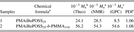
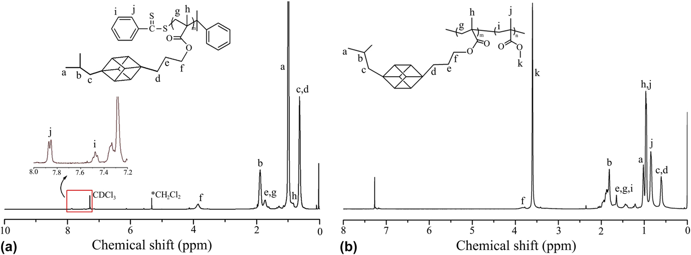
In the polymerization of PMAiBuPOSS, AIBN was used as initiator and CDB as RAFT agent, because CDB could serve as a convenient vehicle in mild experiment conditions and lead to narrow molecular weight distribution. Reference Deng, Bernard, Alcouffe, Galy, Dai and Gérard31 The polymerization results of our block copolymers are listed in Table I. From the polymerization results, we find that the molecular weight of PMAiBuPOSS calculated by NMR is higher than that measured by GPC. This could be attributed to the compact structure of PMAiBuPOSS which is different from that of GPC polystyrene standards. Reference Maeda, Hayakawa, Tokita, Kikuchi, Kouki, Kakimoto and Urushibata34 To synthesize hybrid block copolymer containing POSS, PMAiBuPOSS homopolymer should be synthesized first because of its steric hindrance. PMAiBuPOSS25 (M n,GPC = 8500, PDI = 1.06) was utilized for chain extension in our study. 1H NMR was used for characterization of our resulting polymers. The 1H NMR spectrum of PMAiBuPOSS25 is shown in Fig. 1(a).
The polymerization results of PMAiBuPOSS and PMAiBuPOSS-b-PMMA.
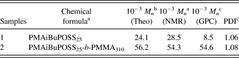
a Chemical formula and M n,NMR of different resulting polymers were determined from the integration of 1H NMR spectra.
b M n,theo of different resulting polymers was calculated from the conversion of monomers which have been mentioned above.
c M n,GPC and PDI of different resulting polymers were determined from GPC analysis.
1HNMR spectra of (a) PMAiBuPOSS25 and (b) PMAiBuPOSS25-b-PMMA310.
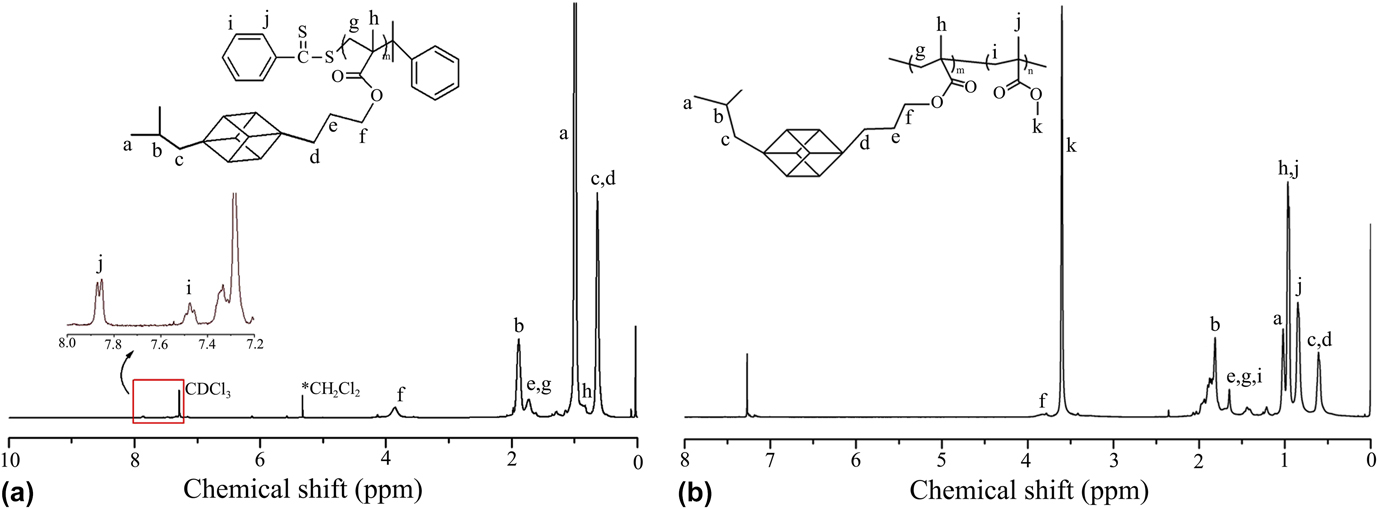
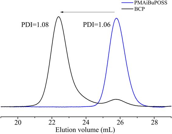
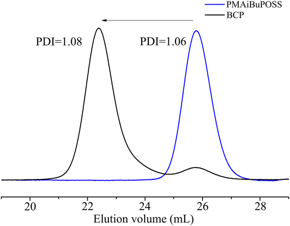
PMAiBuPOSS-b-PMMA block copolymer was later synthesized on the basis of PMAiBuPOSS. The 1H NMR spectrum of PMAiBuPOSS25-b-PMMA310 is shown in Fig. 1(b). Compared with 1H NMR spectrum of PMAiBuPOSS25 [Fig. 1(a)], there was a sharp increasing integration peak at 3.6 ppm, which is assigned to the methylene protons next to ester group in MMA units. GPC analysis also demonstrates the successful synthesis of PMAiBuPOSS-b-PMMA (Fig. 2). That there was no shoulder and tail in the GPC curve of PMAiBuPOSS25 indicated its narrow molecular weight distribution. After further chain extension, chromatograms of PMAiBuPOSS25-b-PMMA310 shift to lower elution volume, indicating that PMAiBuPOSS-b-PMMA has been synthesized successfully. Little shoulder was found in the GPC curve of PMAiBuPOSS25-b-PMMA310 which could be ascribed to dead chain of PMAiBuPOSS25 and some resulting polymers of coupling termination.
GPC traces of PMAiBuPOSS25 and PMAiBuPOSS25-b-PMMA310.
B. Preparation and morphology observation of hybrid nanostructured epoxy-amine networks
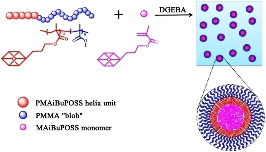
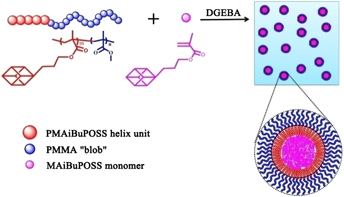
POSS was found insoluble in DGEBA, Reference Verchère, Sautereau, Pascault, Moschiar, Riccardi and Williams35 on the other hand, PMMA has good compatibility with DGEBA (δPMMA = 21.52 MPa0.5; δDGEBA = 20.9 MPa0.5). Reference Verchère, Sautereau, Pascault, Moschiar, Riccardi and Williams35,Reference Jaffrennou, Portal, Méchin and Pascault36 We tried to use the POSS-based block copolymer with PMMA segment (PMAiBuPOSS-b-PMMA, BCP) as compatibilizer to improve the compatibility of epoxy resin and POSS. Figure 3 shows the schematic of the compatibility of epoxy/POSS blends improved by BCP. Owing to its PMMA segment, BCP could self-assemble into micelles in DGEBA with PMMA as the crown, and PMAiBuPOSS as the core. The micelles were widely dispersed in the DGEBA system, making it possible to improve the capacity of POSS monomer in DGEBA. Under this mechanism, which was similar to that of emulsion formation, a large number of micelles were formed by BCP in DGEBA, and POSS monomers were compatibilized into the core of the micelles without reaggregation. By adjusting the ratio of BCP and POSS monomer, a controllable phase structure of POSS-modified epoxy resin could be made.
Schematic of compatibilization of BCP in epoxy/POSS blend system.

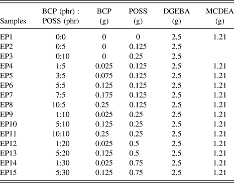
In the preparation of the POSS-modified epoxy resin, we adopted different ratios of BCP to POSS monomer to verify the impact of BCP on the compatibility between POSS and epoxy resin. We chose MCDEA as curing agent, which has good compatibility with DGEBA and PMMA (δMCDEA = 22 MPa0.5), so that the dispersed state of the blend precursor would not change after the curing process. The curing temperature was set based on previous studies, namely 135 °C for 14 h, and post-treated at 190 °C for 4 h, then slowly cooled to room temperature. Reference Ritzenthaler, Court, David, Girard-Reydet, Leibler and Pascault37 The constituent contents of epoxy/POSS blends are illustrated in Table II.
Constituent contents of epoxy/POSS blends.
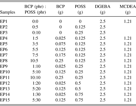
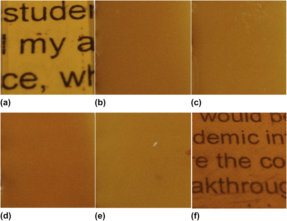
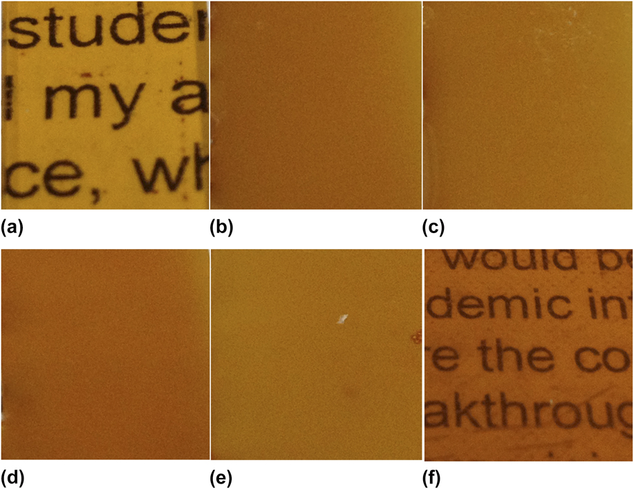
When blending POSS monomer with epoxy resin directly, POSS monomers formed agglomerates because of the strong interaction between POSS molecules and epoxy resin. EP2 and EP3 were products of blending with different ratios of POSS to epoxy. Whether we elevated melting temperature or prolonged stirring time, POSS could not disperse in the epoxy resin uniformly, and showed visible phase separation. Figure S2 showed the optical images of EP2 before curing process, in which white POSS aggregations were floating on the surface of epoxy. When BCP was added as compatibilizer, the result was different. In EP4–EP8, we fixed content of POSS at 5 phr and added BCP with the content of 1 phr, 3 phr, 5 phr, 7 phr, and 10 phr, respectively. In EP4, for example, the DGEBA solution was translucent and homogeneous without obvious POSS agglomerates, because the compatibility between POSS and epoxy was significantly improved. Figure 4 illustrates the optical images of cured epoxy samples, which were photographed on a white paper. The results showed that pure epoxy has excellent light transmission. In EP4–EP7, when BCP and POSS monomer were added, samples were translucent because of the obvious phase separation in the blends, which was attributed to the strong interaction between POSS monomer molecules. However, when the content of BCP was over 10 phr, the sample became transparent again, as illustrated in Fig. 4(f), indicating that the compatibility between POSS monomer and epoxy was significantly improved. The above results indicated that BCP could effectively improve the compatibility of epoxy resin and POSS owing to its amphiphilicity in epoxy. In order to further understand how BCP improved the compatibility between epoxy and POSS monomer, we used SEM to observe the morphology of the samples.
Optical images of (a) EP1, (b) EP4, (c) EP5, (d) EP6, (e) EP7, (f) EP8 after curing process.
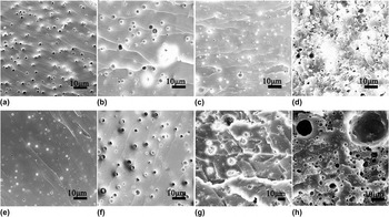
We observed the morphology of the modified epoxy by immobilizing the content of BCP and changing the content of POSS monomer. Figure 5 showed the SEM images of fracture surface of epoxy/POSS blends with 5 phr, 10 phr, 20 phr, and 30 phr POSS monomer content, when BCP content was 1 phr and 5 phr, respectively. The fracture surfaces of all cured samples were etched in dichloromethane to remove POSS, for dichloromethane is a good solvent for POSS. After etching, the POSS-rich areas of epoxy formed plenty of holes, while the epoxy matrix was not destroyed. Reference Liu, Zheng and Nie38 The dispersion of POSS in the epoxy resin could be figured out by observing the distribution of the holes, which was attributed to the effect of BCP.
SEM images of fracture surface of epoxy/POSS blends with (a) 5 phr, (b) 10 phr, (c) 20 phr, and (d) 30 phr of POSS monomer, when BCP = 1 phr; with (e) 5 phr, (f) 10 phr, (g) 20 phr, and (h) 30 phr of POSS monomer, when BCP = 5 phr. Surface was etched in dichloromethane.

As shown in Fig. 5, when the content of BCP was 1 phr, the increase of POSS monomer content caused a increase in the scale of POSS-rich area gradually in the epoxy. When the content of POSS monomer was 5 phr, the diameter of the POSS-rich area was about 1 μm, with uniform size and narrow distribution. With the increasing content of POSS monomer, as the POSS-rich area became larger, the uniformity of distribution was destroyed. When the content of POSS monomer reached 30 phr, the etched fracture surface was filled with anomalous holes with size ranged from 5 to 15 μm. The distribution of POSS was transformed from microphase separation to macroscopic phase separation. In the case of BCP with 5 phr, the increase of POSS content also resulted in the same pattern, but the size of the holes was ranked within 0.5–1 μm. When the content of POSS monomer reached 30 phr, anomalous holes were greater than 10 μm, apparently. We also used software to analyze the diameter of holes in these SEM images, as illustrated in Fig. S3. The obtained result demonstrated that more BCP should be used to make POSS monomers disperse uniformly if more POSS monomers were blended.
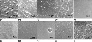
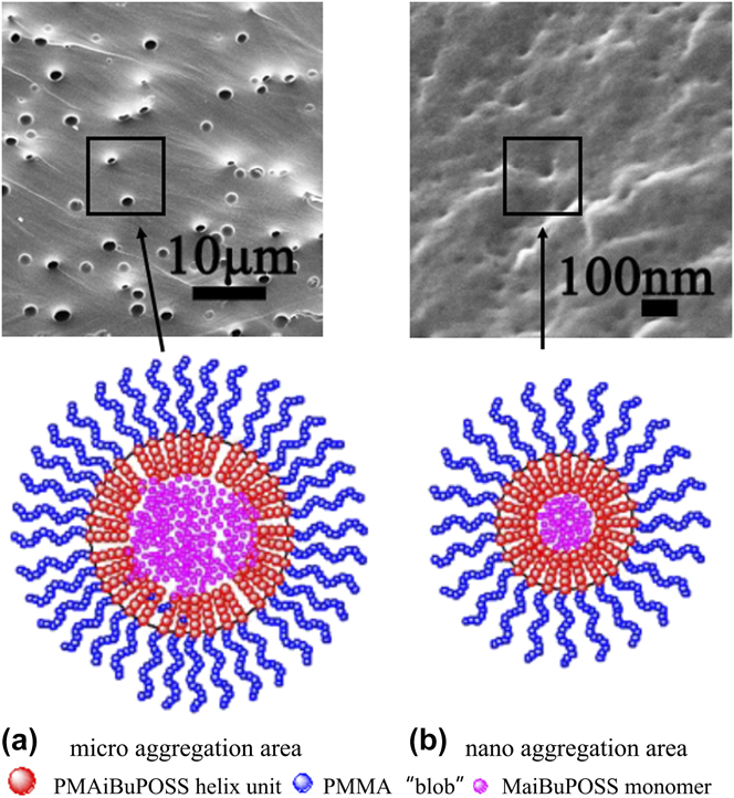
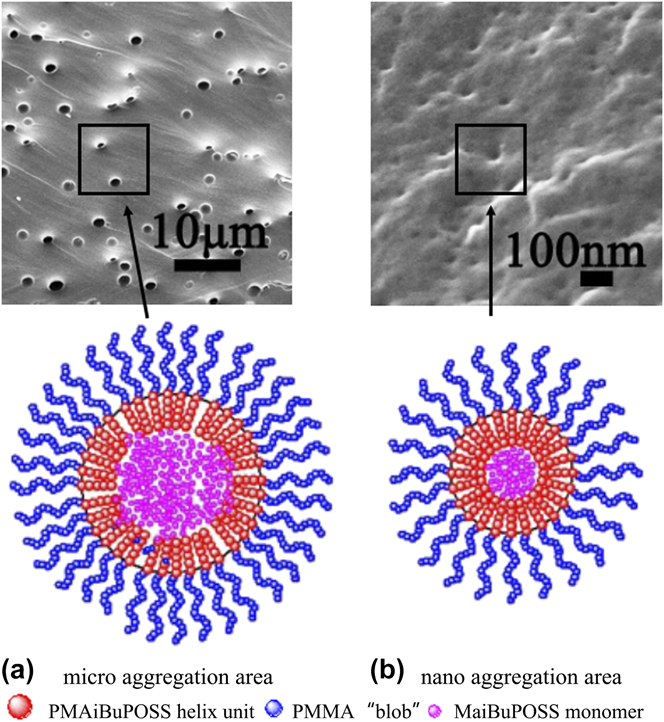
We further prepared epoxy/POSS blends with fixed content of POSS monomer and different content of BCP, and then observed the morphology of the modified epoxy. Figure 6 displayed the SEM images of fracture surface of epoxy/POSS blends prepared by using 5 phr of POSS monomer and various contents of BCP ranging from 1, 3, 5 to 7 phr. The fracture surfaces of cured samples were etched in dichloromethane before observation. As shown in Fig. 6, when the content of POSS monomer was fixed at 5 phr, it was surprising to find that the POSS-rich domains were not dispersed in the epoxy matrix with a certain size. For example, in EP4, under lower magnification (1000x), holes with the size of 1–2 μm were obvious, but some nano-sized small holes could also be observed under higher magnification (20000x). It revealed that POSS monomers dispersed in epoxy matrix into two scales, 1–2 μm scales and 10 nm scales, and in each scale, the POSS-rich areas were uniformly dispersed. Herein, we referred this kind of distribution as “secondary distribution”, as shown in Fig. 7. The secondary distribution became more obvious when the content of BCP increased. With the increase in the content of BCP, the amount of 1–2 μm POSS-rich areas decreased, while that of 10 nm POSS-rich areas increased. As shown in Figs. 6(e) and 6(j), in EP8, no 1–2 μm POSS-rich areas were observed with magnification of 1000, and under higher magnification (20000x), a great number of nanosized POSS-rich areas were observed, which could also be verified by its better transmittance. This is understandable, when the content of BCP was low, each micelle in epoxy had to encapsulate a large number of POSS monomers, thus resulting in the larger size of POSS-rich area; while, when the content of BCP was high enough, the number of micelles increased and less POSS monomers were compatibilized in each micelle. So, BCP played a positive role in improving the compatibility between POSS and epoxy.
SEM images of fracture surface of epoxy/POSS blends with (a, f) 1 phr, (b, g) 3 phr, (c, h) 5 phr, (d, i) 7 phr, and (e, j) 10 phr of BCP content in lower magnification (a, b, c, d, e) and higher magnification (f, g, h, i, j), when POSS monomer content was 5 phr. Surface was etched in dichloromethane.

SEM images of fracture surface of EP4 with magnification of 1000 (a) and EP8 with magnification of 40,000 (b), the models below represent POSS-rich area with different sizes.
C. Fracture behavior of hybrid nanostructured epoxy-amine networks
Tough epoxy has many good properties; however, its brittleness is an immense obstacle for application. Many researchers were committed to overcome this shortcome. As we know, the fracture morphology could largely reflect the fracture behavior of a material. Reference Zhang, Liang, Wang and Ren28,Reference Fu, Shi, Chen, Yuan, Wu, Liang and Zhong29 In this article, the toughness of samples was analyzed by observing the fracture behavior of the POSS-modified epoxy resin.
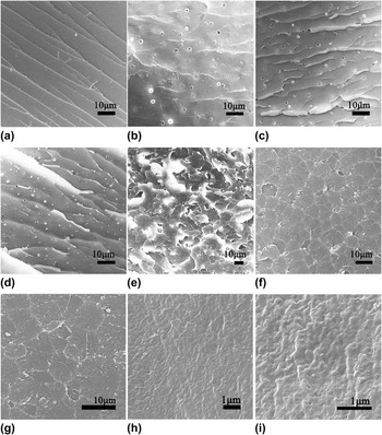
Figure 8 showed the SEM images of fracture surface of neat epoxy and epoxy/POSS blends with different content of BCP, which were quenched and fractured in liquid nitrogen before observation. We found that the fracture surface of neat epoxy was quite smooth with striped rifts, which was the typical morphology of brittle fracture. Reference Zhang and Jia39 When BCP and POSS were added to the epoxy matrix, for example in EP4, the fracture surface was no longer smooth, and the rifts were more distorted. With the increase in the content of BCP, from EP5 to EP7, new morphology emerged: irregularly layered rifts were found in EP5; torn strip-like fibers were found among the layered rifts in EP6; the fracture surface was extremely rough and scaly in EP7. These fracture morphologies implied that the fracture area of the material was gradually increasing, and the material was transformed from brittle to tough. Such changes were consistent with the changes of the fracture morphology of toughened epoxy as reported by Zhang and Jia. Reference Zhang and Jia39 When the content of BCP reached 10 phr, nanosized POSS monomers were dispersed in the epoxy matrix, and the fracture surface was totally different. As shown in Figs. 8(f)–8(i), regular polygonal cracks consisting of countless plastic fracture tips were found in the fracture surface, which looked rough in higher magnification. We believed that the large size of POSS-rich area could cause stress concentration and generate large rifts, although the POSS cage structure could absorb impact energy. However, when POSS monomers were of nanosize dispersion in the epoxy matrix, the POSS-rich area acted as a rivet to prevent the development of cracks. Reference Jones, Zhou, Jeelani and Mabry40 As a result, it also balanced stress in the material, which made the fracture surface flat with distributing polygonal cracks. Meanwhile, nanodispersed POSS also absorb a lot of impact energy, resulting in large numbers of plastic fracture tips. It is expected that the toughness of epoxy got significant improvement when POSS dispersed in epoxy matrix in nanoscale.
SEM images of fracture surface of neat epoxy (a), epoxy/POSS blends EP4 (b), EP5 (c), EP6 (d), EP7 (e), EP8 (f) with magnification 1000 and EP8 with higher magnification 2000 (g), 10,000 (h) and 20,000 (i).

D. Thermal–mechanical behavior of hybrid nanostructured epoxy-amine networks
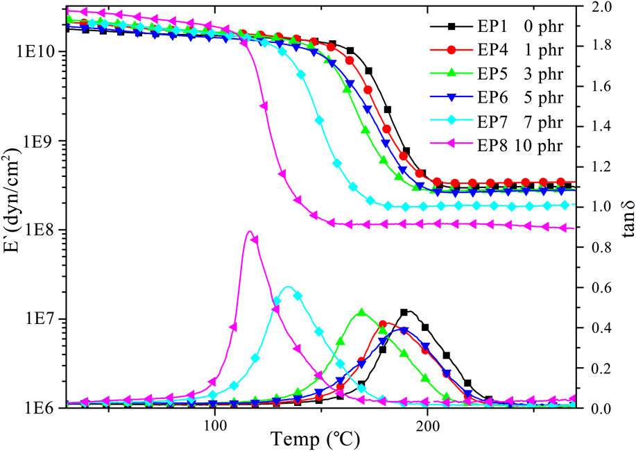
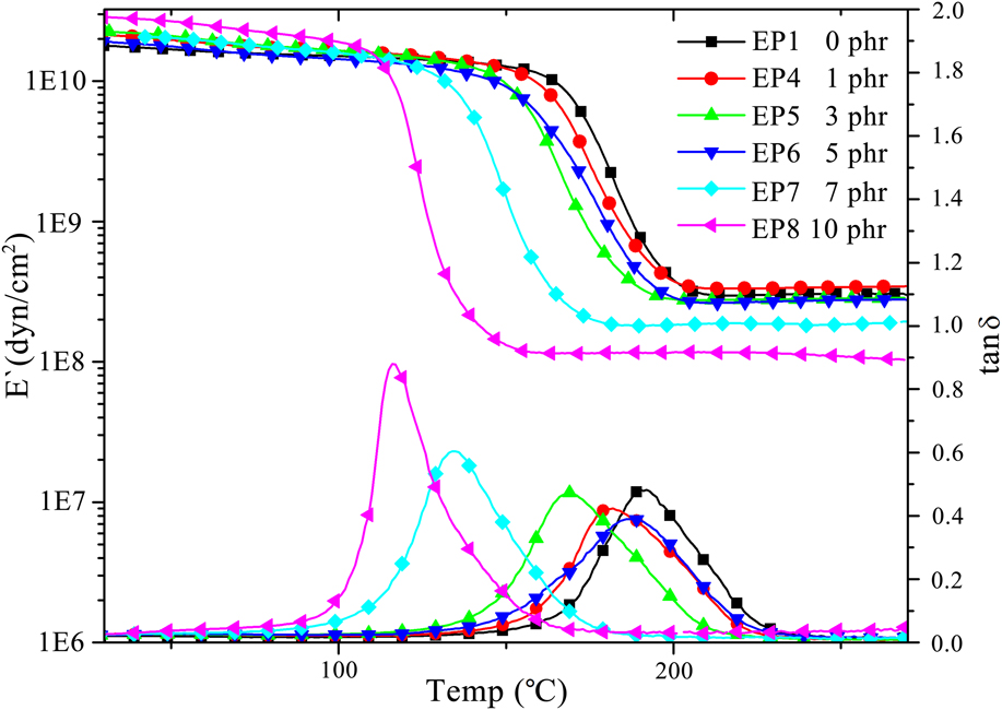
When evaluating the performance of epoxy resin, the thermal–mechanical behavior is also very important. Thus, we also studied the thermal–mechanical behavior of POSS-modified epoxy was also studied by DMTA, as shown in Fig. 9. The sudden change in storage modulus E′ and the unimodality of loss tangent meant no macrophase separation occurred in POSS-modified epoxy EP4–EP8, which was in accordance with the SEM characterization results. With the increase in BCP content, the storage modulus E′ increased at the glassy state (T < T g), which was larger than that of neat epoxy, but gradually decreased at the rubbery state (T > T g). It indicated that POSS as a rigid filler played a role in enhancing the modulus at the glassy state particularly when POSS dispersed in epoxy. On the other hand, POSS-rich area self-assembled by POSS and BCP, acted as plasticizer in the epoxy matrix, which increased the distance between epoxy chains and reduced the amount of crosslinking points. Meanwhile, storage modulus E′ of PMMA block in BCP was also lower than that of epoxy. Reference Remiro, Marieta, Riccardi and Mondragon41 Therefore, modulus at the rubbery state decreased while BCP content increased. The glass-transition temperature was valued from the peak of the loss tangent curve. Obviously, T g constantly decreased with the increasing of BCP, as BCP was a block copolymer composed of POSS segment and PMMA segment. While increasing the content of BCP, the content of POSS was also increased. As described above, POSS played a role as plasticizer, increased the distance between epoxy chains, and decreased the amount of crosslinking points. We also observed that with the increase in the content of BCP, the peak height of tanδ increased, and the peak width was narrowed. Because the increase of the content of BCP led to a higher content of POSS, as rigid molecule in large dimension, increased the internal friction when the glass transition was carried out; at the same time, POSS dispersed in epoxy trended to nano and homogenization. Despite the increase of BCP made POSS dispersed at nanosize in epoxy, the thermal–mechanical behavior was not improved, but declined to a certain degree.
DMTA results of epoxy/POSS blends with different contents of BCP.
The synthesis route of PMAiBuPOSS-b-PMMA via RAFT polymerization.

IV. CONCLUSIONS
In summary, this article has described a novel POSS-based BCP synthesized by RAFT polymerization. BCP were used as compatibilizer to improve the compatibility of epoxy resin and POSS. The SEM results demonstrated that POSS dispersed in epoxy at two states under the compatibilization of BCP: the microaggregation state and the nanoaggregation state. Moreover, the amount of microaggregation areas of POSS decreased when the content of BCP increased, but the amount of nanoaggregation areas of POSS increased. When the content of BCP reached 10 phr, POSS were distributed in epoxy matrix in nanosize uniformly, which revealed that the novel POSS-containing block copolymer could effectively improve the compatibility of epoxy resin and POSS due to its amphiphilicity in DGEBA derived from the coexistence of PMMA segment and PMAiBuPOSS segment. The study on the thermal–mechanical behavior of epoxy/POSS blends via SEM and DMTA demonstrated that their fracture behavior transformed from brittle fracture to ductile fracture gradually with the increase of BCP content; however, the T g and E′ at the rubbery state decreased.
Supplementary Material
The figures showing 13C NMR spectrum of PMAiBuPOSS25-b-PMMA310, the optical image of EP2 before curing process, and size distribution of micelles on the fracture surface of epoxy/POSS blends with different content. To view the supplementary material for this article, please visit http://dx.doi.org/jmr.2014.364.
ACKNOWLEDGMENTS
This work was financially supported by the National Natural Science Foundation of China (51273164 and U1205113), the Fundamental Research Funds for the Central Universities (2012121031), and NCETFJ.