NOMENCLATURE
- AAIB
Air Accidents Investigation Branch
- AMC
acceptable means of compliance
- AoD
aft of datum
- CAS
calibrated airspeed
- CG
centre of gravity
- IAS
indicated airspeed
- FL
flight level (=sHp/100 ft)
- kCAS
knots CAS
- kias
knots IAS
- MAC
mean aerodynamic chord
- MAP
manifold air pressure (expressed in inches of mercury/“Hg)
- MCP
maximum continuous power
- mias
mph IAS
- MTOM
maximum take-off mass
- N 1
lower speed positive normal acceleration limit for an aeroplane
- N Z
normal acceleration (also termed load factor)
- N Z.max
maximum normal acceleration (or load factor) experienced
- PEC
position and pressure error corrections (between IAS and CAS)
- R2
coefficient of determination, defining the quality of a line fit, has value R 2=1 for perfect line fit, R 2=0 for totally random distribution. Defined by
 $$R{\equals}{{n \sum xy{\minus} \sum x \sum y} \over {\sqrt {n\left( { \sum x^{2} } \right){\minus}\left( { \sum x^{2} } \right)} \sqrt {n\left( { \sum y^{2} } \right){\minus}\left( { \sum y^{2} } \right)} }}$$
- rpm
engine speed (revolutions per minute)
- sHp
standard pressure altitude (1013.25 hPa subscale setting)
- V A
Manoeuvre speed
- V H
maximum achievable airspeed in level flight
- V min
minimum airspeed experienced
- V NE
maximum permitted airspeed in flight.
- V S0
stall speed in the landing configuration

1.0 INTRODUCTION
1.1 The background and hypothesis
A 2018 Air Accident report( 1 ) concerning a fatal accident to an EV97 Eurostar aircraft suggested a potential mechanism by which an aeroplane might be destroyed, although did not conclude that this was necessarily the cause of that accident. Specifically it suggested that a sudden rearward movement of a lever-type mechanical pitch trimmer might potentially cause normal acceleration to exceed aeroplane structural normal acceleration limits. Potentially related, there has also been at least one other fatal accident in the same aircraft type where some undetermined occurrence did not cause a structural failure but was of sufficient severity to project the pilot from the aircraft( 2 ).
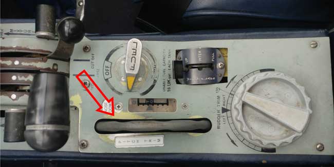
Obviously deliberately causing such an occurrence is inadvisable, and the Air Accidents Investigation Branch (AAIB) commissioned limited flight testing of an aeroplane similar to the accident aircraft in order to demonstrate this potential for that to occur. This paper details a broader and independent investigation which further investigated this potential. Four aeroplane types were flight tested: an EV97 Eurostar( 3 ) (similar to the original accident aircraft), a Scottish Aviation Bulldog 120( 4 ), a Grumman AA5a Cheetah( 5 ) and a Bölkow 209 Monsun 150FF( 6 ). Of these types, only the Eurostar has a trim lever (Fig. 1), all others used a trim wheel and thus whilst those other types are evaluated any conclusion is hypothetical, as if they had a lever rather than a wheel. All four types tested had a similar (low wing, tractor single, side-by-side, nosewheel, fixed gear) configuration although the Eurostar, Bulldog and Monsun are controlled with a stick, and the AA5a solely with a yoke.
1.1 The operation of pitch trimmers
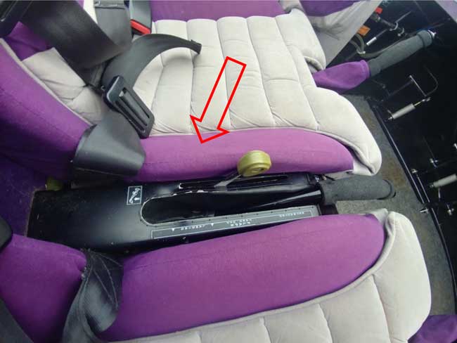
There are several systems in use in light and microlight aeroplane cockpits to control the pitch trim function (most smaller aeroplanes not using roll or yaw trimmers – although of this sample the Bulldog does have a yaw trimmer) the most common is a trim wheel (Fig. 2) necessitating relatively slow action from the pilot to make inputs; many microlight aeroplanes and sailplanes have trim levers and a few light aeroplanes, whilst examples of all aeroplane classes may use electric trimmers. Again most commonly (and the case for all aeroplanes tested here) cables will then operate a trim tab set into the elevator. The pitch trim control is always used to set the hands-off flying speed of an aeroplane, the normally taught method of use being to make that change initially with the primary pitch control (the yoke or stick) and then to use the trimmer to remove the applied force at the primary control until that may then be released.
(Colour online) Pitch trim lever in Eurostar.

(Colour online) Pitch trim wheel in the Bulldog (located between the seats, front of aircraft is to the left of the image, wheel on right of image is yaw trimmer).

2.0 THE MAIN EXPERIMENT
2.1 Data obtained
CAUTION: The following section details tests carried out with due procedural care by qualified test pilots. They should not be attempted by pilots or organisations unfamiliar with flight test technique delivery and associated safety planning.
For each aeroplane, the following tests were carried out, flying at a representative weight and balance condition.
[i] Wind-up turns( 7 ) were flown from a safe altitude and V H, accepting height loss where required, to identify the manoeuvre stability characteristics up to the highest value of normal acceleration that could reasonably be achieved. Normal acceleration reference was taken in the Bulldog and Monsun from the cockpit g-meter, and in the other types from the ‘g-meter free’ app on an LG V20 mobile phone mounted vertically to the instrument panel.
[ii] Tests were flown to evaluate the primary pitch control force which was required to maintain V H through the range of trimmer input.
[iii] For the Eurostar and Bulldog, a racetrack( Reference Gratton 8 ) method pitot-static calibration was carried out to determine airspeed indicator errors (for other types position and pressure error correction (PEC) data in the pilots operating handbook were used.)
Note that in all four aeroplanes tested, V H was the maximum achievable speed with full throttle in level flight, which in all cases did not exceed the maximum power setting for the engine. Many aeroplanes, including the Eurostar, have a lower power limit of maximum continuous power (MCP) which may be for reasons of extending engine life, providing a margin between V H and V NE, or reducing fuel burn and thus permitting an increased empty weight on weight-marginal aeroplanes (this last is common for high performance microlight aeroplanes particularly). However, given that no short term engine limitations would be exceeded, and that achieving periods of high speed level flight is both legally and practically possible in all aircraft types above MCP, V H in this paper corresponds to full throttle, and not any lower published power limit.
2.2 Analysis method
For each aircraft, the data for manoeuvre stability were plotted and linear trendline formed, with extrapolation made out to ≈1.5N 1. The data for control force used to maintain speed with changes in trimmer input was also plotted and a quadratic curve fit made (for the Eurostar this quadratic fit was effectively linear, but retained for consistency). These were then cross-plotted to provide an estimate of the normal acceleration which might potentially be generated and indicate whether potential existed for a step nose-up trimmer input to cause a wing overstress.
2.3 Considerations of data quality
Only two of the aeroplanes were fitted with built in and certified g-meters – the Monsun and the Bulldog. For the Eurostar and the AA5a a smartphone g-meter app (g-meter free on an LG V20 phone) was used. On the Monsun both were flown together, and throughout the normal acceleration range flown, the two agreed to within 0.1 g, which was considered adequate for the purposes. It was considered that all g-meter readings were in any case readable to about ±0.05 g.
Graphs show a perhaps slightly conservative +/−0.1 g error bar, +/−0.45daN (1lbf, based upon readability of the cockpit force gauge) and variable error bars for trimmer authority depending upon test pilot opinion of the ability to measure trimmer position in each aircraft type.
Airspeed is difficult to control in such manoeuvres, but this was simplified by the use of a single speed for all tests in each aircraft. In all cases, the test pilot judged that he was able to maintain conditions at the test point to within ±5 kias at the point data were taken. Inevitably altitudes did change during tests, but at all points within +200/–600 ft of the stated condition.
All tests (except for the simulated step trimmer inputs in the Eurostar) were flown by the same test pilot, who was current on the Monsun, Bulldog and AA5, and had prior experience on the Eurostar but flew for these tests with a safety pilot current and experienced on type. Hours on type prior to the tests were the following: Monsun 4 h, Bulldog 38 h, AA5 210 h, Eurostar 1 h. The Eurostar step-out-of-trim tests (‘Second Eurostar’) were flown by a second test pilot with 500+ hours on type.
3.0 RESULTS AND DISCUSSION
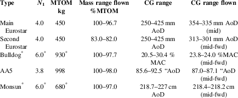
Aircraft were tested at the conditions shown in Table 1.
Characteristics of each type as flown

* Aerobatic limits, within which the Bulldog and Monsun were operated for these tests.
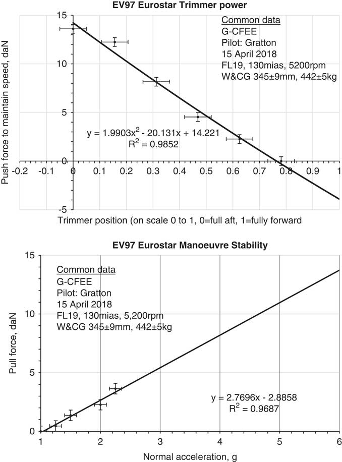
Data for the Eurostar, which was tested at 1,900 ft sHp, V H=130 mias (109 kCAS), 5,200 rpm (using 5-min power: maximum continuous power and thus V H are somewhat lower) are shown in Fig. 3. The pitch control force (stick force) to exceed N 1 in the EV97 at the test condition was about 8 daN, and to exceed this plus the standard 50% structural safety factor between limit and ultimate loads was 14 daN. The stick force to maintain flight speed at the test condition, if the pitch trimmer was deflected suddenly fully nose-up (to the back stop) was about 14 daN.
Results for the EV97 Eurostar.

The first figure is clearly approximated, since to conduct a fully representative test would be unsafe, but this indicates that a sudden full-rear deflection of the pitch trimmer would almost certainly cause the aircraft to exceed N 1 and shows significant potential to meet or exceed the ultimate load.
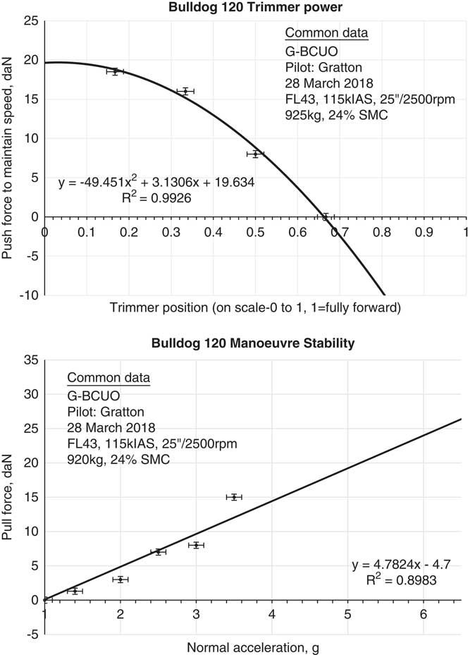
Data for the Bulldog, which was tested at 4,300 ft sHp, V H=115 kias [114 kCAS], 25'' MAP, 2,500 rpm are shown in Fig. 4; using a quadrilateral fit to the trim authority data and linear to manoeuvre stability this indicates that a sudden full nose-up trim input (which would not actually be possible due to the nature of the control) would create the equivalent of about 20 daN, which in turn would create a normal acceleration of about 5 g. This is within the 6 g aerobatic limit for the aeroplane, and thus whilst it would be dramatic, would not risk structural failure. It does seem not unlikely, however, that at a higher weight where the normal acceleration limit reduces to 4.4 g, a structural limit might theoretically be exceeded, if the trim control permitted such an input.
Results for Bulldog 120.

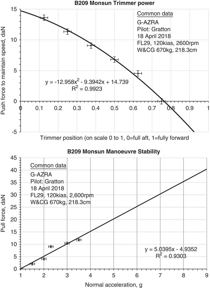
Data for the Monsun, which was tested at 2,900 ft sHp, V H=120 kias, 2,600 rpm are shown in Fig. 5; using a quadratic fit to the trim authority data and a linear fit to the manoeuvre stability data. This indicates that if it were possible, a step fully nose-up trim input would be equivalent to about a 15 daN sudden back-stick pressure. This in turn would create a normal acceleration about 3.4 g, well within any structural limits.
Results for Bölkow B209 150FF Monsun.

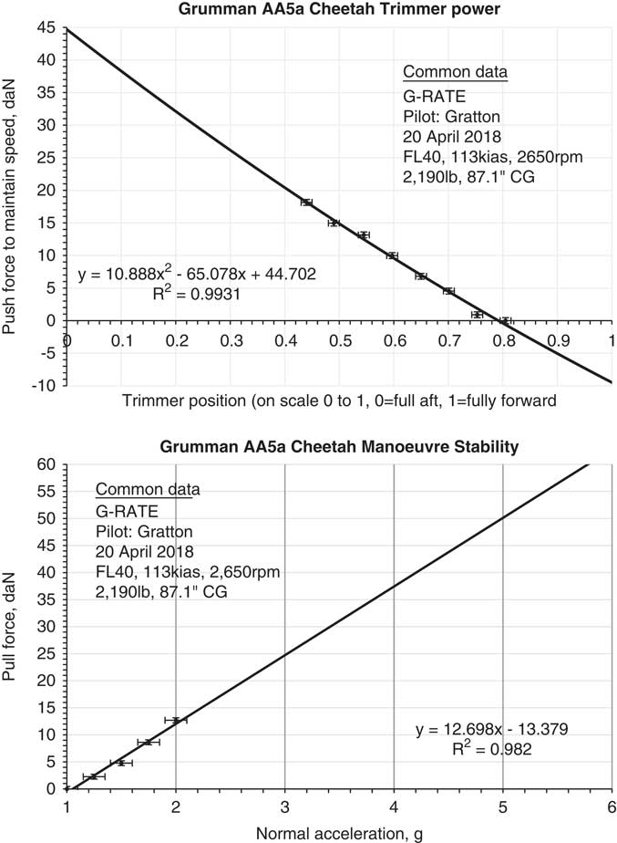
Data for the Grumman AA5a Cheetah, which was tested at 4,000 ft sHp, V H=113 kias [114 kCAS], 2,650 rpm are shown in Fig. 6; using a quadratic fit to the trim authority data and a linear fit to the manoeuvre stability data. This indicates that if it were possible, a step fully nose-up trim input would be equivalent to about a 45 daN sudden back-stick pressure. This in turn would create a normal acceleration about 4.5 g, which is above the aeroplane’s 3.8 g operating limit. However, the trim wheel required about 15 turns to move from the initial setting to the theoretical full back stick condition which was then tested on the ground and required about 11 s of vigorous input, during which period, in the air, aeroplane flight conditions would change, including significant reduction in airspeed. Therefore, the aircraft is protected by the nature of trim inceptor mechanisation, without which there might be a problem with this aircraft – this is explored further in Section 6.
Results for Grumman AA5a Cheetah.

4.0 PROTECTION BY THE O-A CURVE
4.1 How the O-A curve works
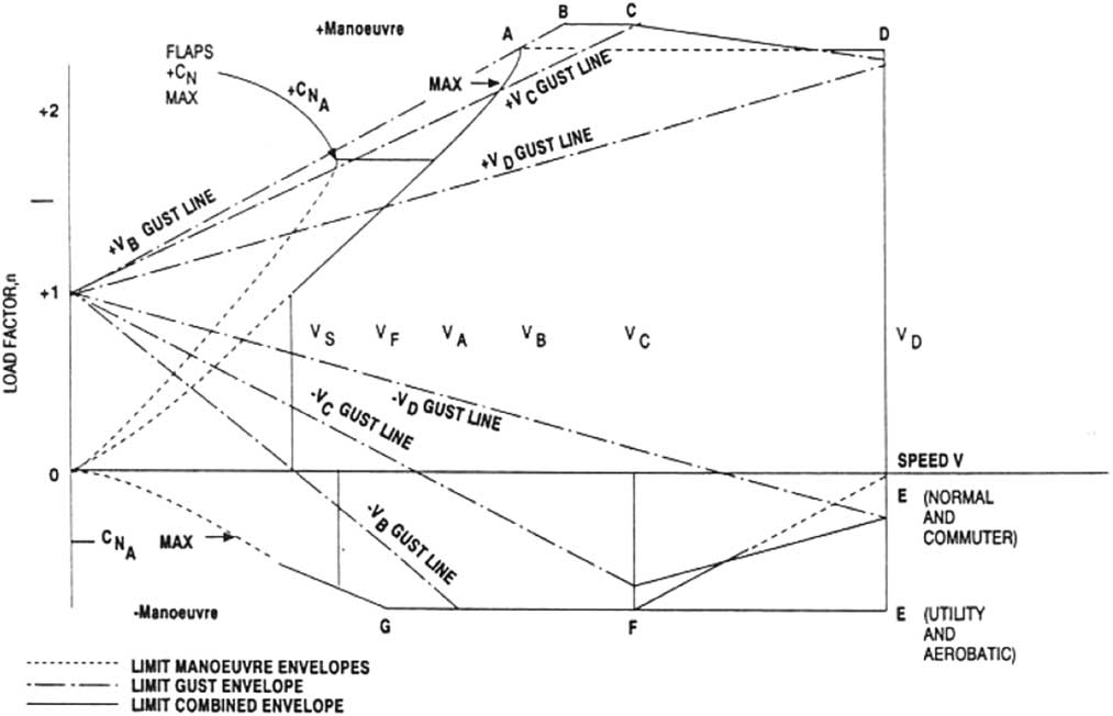
It is well known that the O-A portion of the classic V–N diagram ‘flight envelope’ as shown in Fig. 7 is supposed to prevent an exceedence of N 1 so long as an aircraft is kept below V A ( Reference Gratton 9 ); the protection mechanism is that the aeroplane should stall before structural limits are exceeded. Very high pitch rates will most likely delay the onset of the stall, however there is also a 1.5 safety factor (or greater) in most aircraft between the authorised flight envelope and ultimate conditions, and also airworthiness standards normally require that ultimate conditions can be withstood for at least 2 s without any permanent deformation; hence that protection should remain.
Typical basic flight envelope diagram (from CS.23( 13 ) – an applicable airworthiness standard for the Bulldog, Monsun and AA5a); apart from numeric limits, these diagrams do not vary significantly between airworthiness standards and this may be considered to apply equally to smaller (e.g. CS.VLA( 14 )) aeroplanes as well as military aeroplanes. Microlights such as the Eurostar, unless relatively high performance, are certified in its entirety to BCAR Section S( 13 ) and will not consider gust loadings which, in any case, are irrelevant to the O–A curve. Whilst this figure faithfully replicates the figure in CS.23, in fact V S on the O–A curve is at 1g and V A is at N 1 (typically 3.8 g–6.0 g).

Above V A this protection does not exist, and aircraft are reliant upon a combination of piloting skill and judgement preventing overstress, and the extant safety factors. Generally experience shows that these strategies are adequate – however it is definitely true that many aeroplane types can exceed V A in level flight, and virtually all aeroplane types can exceed V A in a dive.
4.2 Specifics
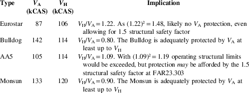
Table 2 compares V H to V A for each of the aeroplane types tested.
V A versus V H for types as tested

The implication here is that some aeroplanes have sufficient margin at maximum level flight speed that even if there was a sudden nose-up control input, the aircraft is unlikely to exceed structural normal acceleration limits. However, this is not universal – in the sample of four aeroplanes tested here, only two: the Bulldog and Monsun (both aerobatic, the higher g-limits thus increasing V A) will be thus protected. However, the AA5 would exceed normal operating limits, and the Eurostar shows strong potential to exceed ultimate limits (being defined as the normal limit multiplied by the structural reserve factor, which is most commonly 1.5 or slightly greater).
5.0 AIRCRAFT BEHAVIOUR FOLLOWING RAPID TRIM INPUTS
5.1 Simulated step trimmer input (Eurostar)
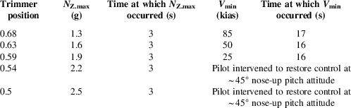
The impact of simulated step trim inputs were evaluated on a different EV97 Eurostar G-CEAM at mid-fwd (303–313 mm) centre of gravity (CG) position and 370 kg/83% MTOM. From V H (trimmer position 0.73, 108 kCAS, 4,000 ft sHp), the trimmer was deflected, in the nose-up sense, in successive tests to positions 0.68, 0.63, 0.59, 0.54 and 0.5 whilst holding the aeroplane on condition using the primary pitch control. The pitch control was then released, thus simulating a step trimmer input. The results are shown in Table 3; these results specifically for maximum normal acceleration match closely the results for the other aircraft in Fig. 3.
Results of simulated step trimmer input at high speed – EV97 Eurostar

Results for this test do not indicate that speed bleed off was sufficient to prevent an overstress, and thus that characteristic does not provide significant protection.
5.2 Simulated step trimmer input (AA5)
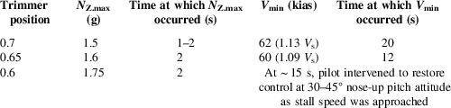
In order to determine whether the relatively low mass and inertia of the Eurostar created particular responses to a step input, the above test was repeated with the AA5a only. That was flown from V H (trimmer position 0.8), with the trimmer deflected to positions 0.7, 0.65 and 0.6 whilst holding the aircraft on condition using the primary pitch control. The pitch control was then released, thus simulating a step trimmer input. Results are shown in Table 4. These results correspond closely to those in Fig. 6 with regard to maximum achieved normal acceleration. The implication of this test is that whilst speed bleeds off with a step trimmer input, this happens substantially slower than the increase in normal acceleration. Therefore the bleed off of speed is, to an even greater extent than for the Eurostar, too low in rate to provide structural protection.
Results of simulated step trimmer input at high speed – Grumman AA5

The tests above were not repeated on the Bulldog or Monsun, whose characteristics sat between the Eurostar and AA5.
5.3 Maximum rate input on a trim wheel (AA5)
As has previously been noted, all types tested here except the Eurostar use a pitch trim wheel, not a lever. On the ground (so with no air loads) from the high speed trim condition this takes about 11 s to be moved the fully back position in the AA5. However in the air there will clearly be both air loads upon the system, and an aircraft response. So at the same V H [113 kias/114 kCAS, full throttle, 0.8 trim position] initial trim condition used for all other tests, the pilot released the primary flight controls and made the highest rate nose-up input to the pitch trim wheel that he was able. As expected, this caused the aeroplane to pitch nose-up increasing normal acceleration and reducing airspeed.
After about 8 s, the trimmer reached position 0.6, by which point speed had reduced to 80 kias, the aeroplane had pitched to an extremely unusual pitch attitude of about 45° nose-up. The g-meter registered a peak normal acceleration during this period of 1.5 g, but this was transitory and by the 8 s point it was closer to 1.0 again. At that point the pilot elected to regain normal control of the aircraft by reducing power and pitching nose-down.
The conclusion of this test therefore is that the use of a manual trim wheel, as enjoyed in this sample by the Monsun, AA5 and Bulldog (and whilst not tested, by the majority of other light aeroplanes such as the Piper PA28 and Cessna 172) would appear to provide good protection from the overstress, and also the induced steep nose-up pitch attitude provides extremely clear cues to the pilot that the aeroplane was entering an undesirable set of flight conditions, and that they should make remedial control inputs. Making such corrections did not require exceptional piloting skill: only inputs as would typically be taught to pilots in order to effect a ‘recovery from unusual attitude’( Reference Halstead and Newton 10 ).
6.0 HOW MUCH TRIM AUTHORITY IS ACTUALLY NEEDED?
An obvious question when considering the potential problems caused by excessive pitch trimmer authority, is how much nose-up trim authority is actually needed? This was evaluated here on the Eurostar and the AA5. With the main Eurostar aircraft at mid-CG, it was found that the greatest requirement during these flights was in order to trim to approach speed powered (typically about 1.3V S0) during final approach segment of the flight: about position 0.34. With the second Eurostar at mid-fwd CG for a glide approach it was 0.23. On the AA5, the critical case was the flapless take-off, where the trimmed setting was about 0.3.
This would correspond on these two aeroplanes to about 3.8 g and 4.4 g (Eurostar) and for the AA5 about 3.2 g. Therefore, there is a strong indication here that aeroplanes may be being built with greater nose-up trim authority than is actually required for operational necessities.
This is of course less straightforward than presented here, as both manoeuvre stability and trim authority are likely to vary in such aeroplanes with CG position and, to a lesser extent, with weight. However, they are also likely to vary in the same sense (that is, at both lighter weights and further aft CG both primary pitch authority and trim power will increase) so determination of a maximum required pitch trimmer setting would appear to be straightforward. Once that was determined, the design solution may in some types, presumably, be a simple case of introducing a mechanical stop: the limited observations of this trial suggest that this may be the case for both the Eurostar and the AA5, although that is rather less clearcut for the Eurostar.
7.0 DISCUSSION: RELATIONSHIPS TO DESIGN CODES
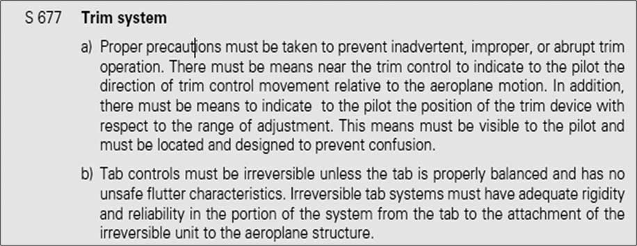
The Eurostar microlight variant in the UK is approved using to BCAR Section S( 11 ), which at present is at issue 6, an excerpt from which is in Fig. 8; that information is not accompanied by any associated interpretative material.
Pitch trimmer requirements from BCAR Section S issue 6( 13 ).

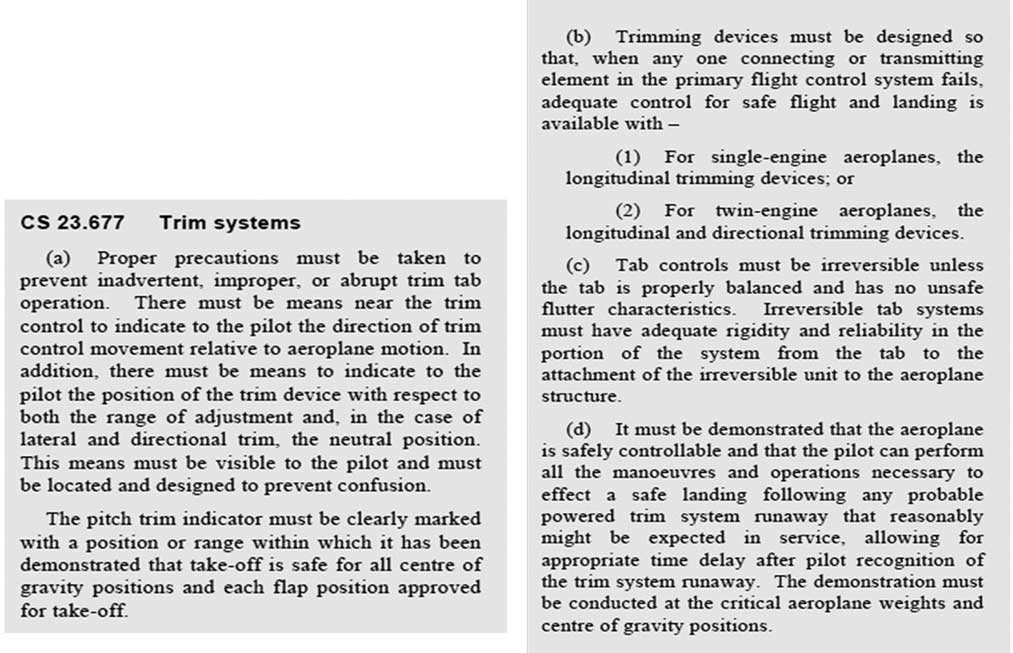
The history of airworthiness standard applicability for the other three types tested here is somewhat complex, but the present standard that would be applied to such aircraft is Part 23, typified by CS.23 issue 4( Reference Halstead and Newton 10 ), from which Fig. 9 is an extract. The standard contains significant further interpretative material, but that concentrates upon the potential for a system runaway.
Pitch trimmer requirements from CS.23 issue 4( Reference Halstead and Newton 10 ).

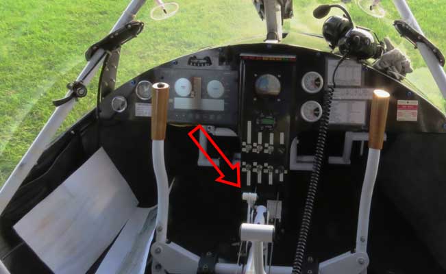
The phrase ‘proper precautions must be taken to prevent inadvertent, improper or abrupt trim tab operation’ might reasonably be interpreted as prohibiting the use of a powerful trim tab lever that is located between seats where it might be accidentally operated. However, the author was unable to find any evidence that this interpretation has historically been considered – for example the X’Air microlight aeroplane, which has an excellent safety record has such a trim lever, albeit further forward in the cockpit (Fig. 10). Reviewing certification reports for the X’Air it has a stick force/g of about 2.5 daN/g and nose-up pitch trimmer authority capable of trimming down to the stall, but is unable to sustain level flight above the V A of 65 kCAS( 12 ), which would presumably provide good protection from overstress due to a step nose-up pitch trimmer input, as would the relatively forward position of the trim lever.
(Colour online) Location of the pitch trim control lever in a Raj Hamsa X’Air cockpit (lever nearer camera is a throttle, black lever on left hand cockpit frame is an engine choke control).

8.0 CONCLUSIONS
This paper appears to confirm the proposal by AAIB that some aeroplanes, and in particular the EV97 Eurostar have a potential through a combination of pitch trimmer design, and the values of manoeuvre stability, V A, V H and pitch trimmer control power, to suffer an in-flight structural failure. However, this paper is not specifically intended to examine the problem of the Eurostar – or whether any other type has a problem, which requires more rigorous evaluation by the appropriate authorities.
The major objective of this paper was to explore the potential of lever-type pitch trimmers to cause overstress in a fixed wing airframe. That case appears to be proven: a lever-type pitch trimmer can cause airframe overstress in the following circumstances:
• A large step nose-up input is possible.
• The equivalent back-stick pressure due to the nose-up stick force per g (manoeuvre stability) gradient and trimmer authority being such as to permit N 1 to be exceeded.
• The aeroplane is able to fly at a speed above V A such that N 1 might be exceeded before the aircraft stalls.
It is further concluded that speed bleed-off during pitch up, whilst it will occur, is unlikely to be of sufficient rapidity, unless proven otherwise, to provide any additional protection.
However, it is also demonstrated that aeroplanes can be protected by one or more of the following:
• High manoeuvre stability (stick force per g).
• Low trimmer power.
• The use of a slow moving pitch trim control that prevents sudden step inputs.
• A manoeuvre speed sufficiently high that it is unable to be routinely exceeded. This might be achieved through thrust/drag combinations that do not allow sufficiently high speed flight and/or a high positive normal acceleration limit.
The author was unable to find previous discussion of this issue, although the fact that the vast majority of Part 23 aeroplanes use a slow-moving trim wheel (such as that in Fig. 2) suggests that this may, in the past, have been ‘common knowledge’ probably prior to 1950, but inadequately documented at that time, and thus has become lost knowledge.
9.0 POTENTIAL FOR FURTHER WORK
The results of this study have been passed to the British Microlight Aircraft Association who are likely in collaboration with the Light Aircraft Association (airworthiness oversight of the EV97 Eurostar is shared between the two organisations), manufacturer and other organisations to co-ordinate further investigation and design changes to the Eurostar particularly.
More generally however, this paper has indicated that a particular combination of pitch trimmer design and manoeuvre stability could allow aeroplanes to be overstressed by a sudden control input, and that there is a lack of clarity in airworthiness standards in regard of this potential. It is not the place of an airworthiness standard to define how to ensure minimum safety standards, only to define what safety standards must be met. It is suggested that some variation upon the following wording might advantageously be added to BCAR Section S, CS.LSA, CS.VLA, CS.22, most likely around paragraph 777 in all cases. In the case of Part 23 (CS.23 and FAR-23) this is probably impracticable because of ongoing moves towards a less prescriptive standard (Ref 9, Chapter 1.3.1.2).
Trim controls shall be designed so that any normally achievable input cannot cause the aeroplane to exceed the normal acceleration limits defined in 337 at any permitted flight condition. Where a control is capable of rapid inputs, this shall include maximum rate inputs to the control stop.
However, the real value of this work should be in interpretation of best practice across light and microlight aeroplane testing – and for most standards this may involve inclusion of advice based upon this research in acceptable means of compliance (AMC) or equivalent material.
This paper tested to a maximum airspeed of V H; whether this is sufficiently conservative for certification, or testing should be extended to V NE would also bear investigation; the latter is clearly a safer solution, but whether this degree of conservatism is essential probably requires community debate to determine. Similarly, where there is a significant difference between MCP and MTOP or full throttle, as with the Eurostar, this is also a necessary debate – as occurred when determining the test conditions for this paper.
10.0 FLIGHT TEST LESSONS LEARNED
Following the convention used in papers published within the flight test community, the author wishes to note and explain two flight test lessons learned in the conduct of this research:
• The simulation of a step nose-up pitch trim input by trimming nose-up whilst holding forward force on the primary pitch control, then releasing the stick was developed by the author and was successful. However the use of small iterations towards what might be a structurally hazardous extreme, with continuous review of results, was deemed essential for safe conduct of the trial.
• During deliberate nose-up trimming whilst holding and measuring forwards stick forces, the risk of an inadvertent control release and resultant overstress was significant. Therefore, the use of an observer ‘guarding’ the controls on the other side of the cockpit was considered highly advantageous.
As all flight was within the certified envelope for the four aeroplanes tested, technically this did not constitute a high risk trial. However, given the nature of the testing: very careful iterative practices were followed, and all tests were flown by a qualified test pilot. It was considered that the second pilot guarding the controls was also beneficial, and their briefing by the test pilot was very specific – carriage of a true passenger would have been unacceptable. A case could be made for solo flight with abandonment capability (i.e. a parachute) but the judgment formed here was that the safety pilot option was the better one.
ACKNOWLEDGEMENTS
The author thanks Cranfield University National Flying Laboratory Centre for permitting the use of the Bulldog aircraft, the syndicate represented by Captain Raymond Blewett-King for permitting use of their EV97 Eurostar aircraft for testing in support of this project. Ben Syson, Chief Technical Officer to the British Microlight Aircraft Association has kindly provided access to some archival flight test data, particularly for the X’Air. The aforementioned plus Cranfield University PhD Student Stephen Daniels flew as Flight Test Observer for some of these test flights and their support in that regard is also gratefully appreciated. The author also thanks Paul Dewhurst of Flylight Airports who kindly provided the aircraft and flew the tests simulating a step nose-up trimmer input in his company’s EV97 Eurostar.