I. INTRODUCTION
Mg and its alloys are very attractive for numerous applications due to their excellent properties such as high specific strength, low density, etc. Reference Mordike and Ebert1,Reference Wang, Mostaed, Cao, Huang, Fabrizi, Bonollo, Chia and Vedani2 However, the lower mechanical properties of Mg and its alloys compared to steel, iron, and Al alloys have limited their applications. Mg single crystal has a low critical resolved shear stress of about 4.8 MPa and its polycrystal exhibits very low strength and hardness. In addition, Mg and its alloys usually exhibit poor plasticity near room temperature due to the limited number of operative slip systems, resulting from a hexagonal close packed (hcp) crystal structure. Reference Zhou, Jain, Wu, Shao, Li and Peng3 Therefore, many different technologies have been used to improve the mechanical properties of Mg alloys. One method to improve the physical and mechanical properties of Mg alloys is to utilize the effective reinforcements. While the carbon nanotubes (CNTs) with superior strength (30 GPa) and stiffness (1 TPa) are considered one of the most ideal reinforcements for metal matrix composites. Reference Yu, Files, Arepalli and Ruoff4
In recent years, CNTs have attracted considerable attention due to their unique mechanical, electrical, and thermal properties and low density. Reference Zhou, Bai, Wang and Xie5 The study on CNTs reinforced Mg and Mg alloy matrix composites has made much progress. Many conventional fabrication methods have been used to produce the composites, such as stir casting, solidification processing, squeeze infiltration, powder metallurgy, and so on. Li et al. Reference Li, Nie and Wang6 have fabricated AZ91D matrix composites reinforced with CNTs and SiCp by using stir casting process and they found that the tensile strength, the elastic modulus, the microhardness and the elongation rate of the composites had been enhanced significantly compared to those of the matrix alloy. Paramsothy et al. Reference Paramsothy, Chan, Kwok and Gupta7 have added CNTs into ZK60A alloy to enhance its mechanical properties using solidification processing followed by hot extrusion and the ZK60A composite exhibited higher 0.2% TYS, ultimate tensile strength, failure strain, and work of fracture (+10%, +10%, +127% and +156%, respectively) than monolithic ZK60A alloy. Park et al. Reference Park, Park, Park, Oak, Kimura and Cho8 prepared AZ91 metal matrix composites reinforced with CNTs by the squeeze infiltrated method and the CNTs/AZ91 composites also exhibited excellent mechanical properties. Improved mechanical properties of AZ91 alloy dispersed with CNTs by powder metallurgy process were reported by Yuan et al. Reference Yuan, Zeng, Liu, Luo, Wu, Wang and Zhou9 However, because of the weak wettability between carbon and metals, the good interfacial bonding between the CNTs and Mg is a challenge for stir casting and solidification processing. Reference Han, Wang, Liu, Li, Du and Du10 Although squeeze infiltration and powder metallurgy method can reduce casting defects such as pores, matrix/reinforcement interface separation, etc., the production process is complex and dangerous. Therefore, the application of the above methods for producing Mg matrix composites is limited to a great extent.
Spark plasma sintering (SPS), also known as plasma activated sintering or pulsed electric current sintering, is based on the generation of high temperature plasmas at the gaps between the compacted powders and offers the superiority of powder metallurgy (PM) technology in addition to the possibility of attaining nearly full densification in high pressure and a relatively short sintering time. Reference Straffelini, Dione Da Costa, Menapace, Zanella and Torralba11 Due to the advantages of higher efficiency, more manageable and environment friendly compared to conventional process, SPS has attracted increasing attention in producing metal matrix composites. Reference Drescher, Witte, Yang, Steuer, Kessler, Burkel, Schick and Seitz12–Reference Muhammad, Sajuri, Mutoh and Miyashita14 Wang et al. Reference Wang, Zhang, Sun, Liu, Hu, Wang, Korznikov, Korznikova, Liu and Osamu15 produced multiwalled CNTs reinforced titanium matrix composites with a high compressive strength of 1106 MPa by SPS. Sule et al. Reference Sule, Olubambi, Sigalas, Asante and Garrett16 have investigated the effect of oxygen content on submicron sized copper and copper reinforced with CNTs using SPS. Zheng et al. Reference Zheng, Ertorer, Li and Zhou17 investigated the mechanical behavior of nanostructured AZ80 alloy synthesized by a cryomilling and SPS approach and found that the compressive yield strength (CYS) and ultimate strength of this alloy reached to 442 MPa and 546 MPa, respectively. However, few attempts have been made to produce CNTs reinforced Mg matrix composites by SPS followed by hot extrusion. Therefore, the present study aims to fabricate Mg matrix composites with excellent mechanical properties by SPS followed by hot extrusion. In this study, Al which was a common solution element in Mg was selected with CNTs as reinforcements in the Mg matrix composites. The Mg–1Al–xCNTs (x = 0.08, 0.15, 0.30, 0.60 wt%) composites with excellent comprehensive mechanical properties fabricated by SPS followed by hot extrusion were reported. The effect of weight fraction of CNTs on the microstructure as well as the mechanical properties of the Mg–1Al–xCNTs composites was investigated.
II. EXPERIMENTAL PROCEDURE
A. Raw materials
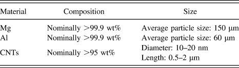
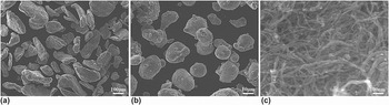
The raw materials used in this study are listed in Table I. Mg powders (99.9% purity, 150 μm particle size) were used as the matrix material. Al powders (99.9% purity, 60 μm particles size) and CNTs (95% purity) with a diameter of 10–20 nm and a length of 0.5–2 μm were used as the reinforcements. Figure 1 shows scanning electron microscopy (SEM) micrographs of Mg powders, Al powders and CNTs.
The experimental materials used in this study.

SEM micrographs of raw powders: (a) Mg, (b) Al, and (c) CNTs.

B. Processing
To prepare Mg–1Al–xCNTs (x = 0.08, 0.15, 0.30, 0.60 wt%) composites with different reinforcements, the content of Al particles was kept constant at 1 wt% while that of CNTs was varied. In the first stage, Al powders and CNTs were mixed by using a planetary ball milling machine under a rotating speed of 200 rpm/min for 3 h in a sealed argon atmosphere. The used milling jars and balls were made of hardened stainless steel and the weight ratio of ball-to-powder was kept at 20:1. In the second stage, the milling balls were taken out and then the pre-weighed Mg powders were put into the milling jars. Subsequently, the Mg–1Al–xCNTs powders continued to be mixed to obtain the homogeneity in the mixtures under a rotating speed of 300 rpm/min for 6 h in a sealed argon atmosphere.
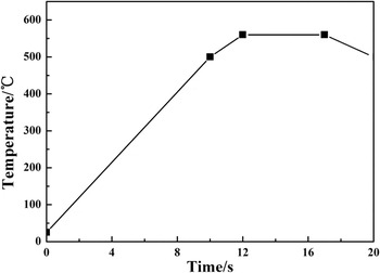
The powder mixtures were consolidated using an SPS-632LX equipment (Fuji Electronic Industry Co. Ltd., Kyoto, Japan). Prior to the SPS process, the mixed powders were poured into a graphite die with internal and external diameters of 40 mm and 55 mm, respectively. The sintering process was performed in a vacuum of 1 Pa under a maximum uniaxial pressure of 50 kN. A contact thermocouple inserted in a round hole with a depth of 15 mm located in the wall of a refractory graphite die was used to measure the sintering temperature. Figure 2 shows the adopted SPS cycle for the mixed powders. First, the mixed powders were heated to 500 °C at a rate of 50 °C/min. Second, the temperature was heated to 560 °C at a rate of 30 °C/min and then was held at 560 °C for 5 min. After that, the applied current was cut off, the pressure was released, and the compacted bulk was cooled down to room temperature. Finally, the Mg–1Al–xCNTs composite bulks with a diameter of 40 mm and a height of 15 mm were produced. The sintered composite bulks were then polished by abrasive paper to remove any surface graphite contamination.
The adopted SPS sintering cycle.

After SPS, the sintered composite bulks were extruded at a temperature of 400 °C to obtain the cylindrical rods with a diameter of 10 mm using a hydraulic press. Prior to hot extrusion, the sintered composite bulks were preheated to 400 °C for 10 min. The extrusion ratio and ram speed were set at 16:1 and 1 mm/s, respectively. For comparison, the cylindrical rod of pure Mg powders (labeled by monolithic Mg) was also produced by the above SPS and hot extrusion process.
C. Testing
The density of as-cast Mg, monolithic Mg, and Mg–1Al–xCNTs (x = 0.08, 0.15, 0.30, 0.60 wt%) composites were determined by Archimedes principle using an electronic balancer with an accuracy of ±0.0001 g. Theoretical densities of the composites were calculated by the rule of mixture assuming no Mg/Al-CNTs interfacial reaction, using the theoretical density 1.74 g/cm3 for Mg, 2.7 g/cm3 for Al, and 2.25 g/cm3 for CNTs. An automatic digital Vickers hardness tester was used to measure the microhardness of as-cast Mg, monolithic Mg, and Mg–1Al–xCNTs composites. Microhardness measurements were made on the polished samples under an indenting load of 0.49 N and a holding time of 5 s.
To study the mechanical properties, monolithic Mg and Mg–1Al–xCNTs composites were subjected to tension and compression tests along the extrusion direction. For comparison, similar tests were also conducted on the as-cast Mg. Dog-bone shaped samples with nominal gage dimensions of 20 mm (length) × 3 mm (width) × 1.5 mm (thickness) were prepared for tension tests, and rectangular prism samples with nominal dimensions of 5 × 5 × 10 mm were prepared for compression tests. The mechanical tests were performed on a Shimadzu AGX-XD 20KN electronic universal testing machine (Shimadzu Instrument Co. Ltd., Suzhou, China) at room temperature under a constant strain rate of 1 × 10⁻³ s−1. Each mechanical test was repeated five times to get the representative results.
Phase analysis of the CNTs, monolithic Mg, and Mg–1Al–xCNTs composites were conducted using a Y-2000XD type x-ray diffraction (XRD; Dandong Tongda Science and Technology Co. Ltd., Dandong, China) with Cu Kα radiation at 36 kV and 26 mA, and a scan rate of 0.02°/s in a range of 10–80°. The microstructures were characterized by using an optical microscopy and a JSM-6700F scanning electron microscope (SEM; JEOL Ltd., Tokyo, Japan) equipped with energy dispersive x-ray spectroscopy (EDS). The fracture surfaces of tensile and compressive samples were also examined by the SEM, using an accelerating voltage of 10 kV.
III. RESULTS AND DISCUSSION
A. Microstructure
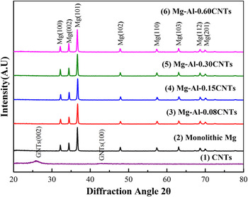
XRD patterns for CNTs, monolithic Mg and Mg–1Al–xCNTs (x = 0.08, 0.15, 0.30, 0.60) composites are presented in Fig. 3. It is can be seen from the figure that the peaks for CNTs are present at 2θ = 25.76 and 43.04°. Most of the peaks corresponding to Mg were identified in these XRD patterns. Different phases of Mg can be observed at 2θ = 32.16°, 34.39°, 36.59°, 47.80°, 57.36°, 63.05°, 68.65°, and 69.99°. However, it is noted that no other peaks except Mg can be observed in all the Mg–1Al–xCNTs composites, which may be due to the very low weight fraction of Al and CNTs in the composites.
XRD patterns of CNTs, monolithic Mg, and Mg–1Al–xCNTs (x = 0.08, 0.15, 0.30, 0.60) composites.

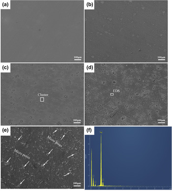
The surface morphology of monolithic Mg and Mg–1Al–xCNTs composites were investigated by SEM. The SEM micrographs of monolithic Mg and its composites are shown in Fig. 4. As shown in Fig. 4(a), the surface of monolithic Mg is smooth and free of micropores, reflecting good bonding between Mg particles. Similarly, there is no boundary between Mg particles and nearly no pores in the Mg–1Al–xCNTs composites. Several micropores were observed in the cluster of CNTs particles in the Mg–1Al–0.60CNTs composites, as indicated by the arrows in Fig. 4(e). Therefore, the SPS followed by hot extrusion is able to make the Mg–1Al–xCNTs composites almost completely densified. In addition, it can be seen from Fig. 4(f) that the presence of Al-CNTs particles in the composites is confirmed by the EDS spectrum. Furthermore, the cluster of hybrid Al-CNTs particles becomes obvious with the increasing fraction of CNTs but they are still distributed uniformly in the composites.
SEM surface micrographs of (a) monolithic Mg, (b) Mg–1Al–0.08CNTs, (c) Mg–1Al–0.15CNTs, (d) Mg–1Al–0.30CNTs, and (e) Mg–1Al–0.60CNTs. (f) EDS of selected area in (d).

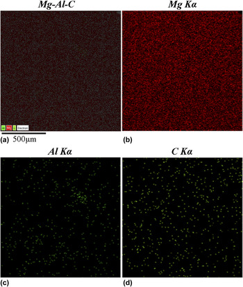
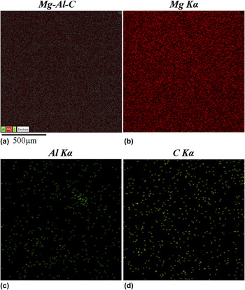
The presence of Al-CNTs particles in Mg matrix is hard to recognize due to the very low weight fraction of Al and CNTs particles. However, to verify the presence of Al-CNTs particles in the Mg–1Al–xCNTs composites, x-ray maps of Mg–1Al–0.15CNTs composite were determined by energy dispersive x-ray spectrometer (as shown in Fig. 5). It is clear from Fig. 5 that Al and CNTs particles are homogeneously embedded in the Mg matrix.
X-ray maps of (a) Mg–1Al–0.15CNTs composite, (b) Mg, (c) Al, and (d) carbon.
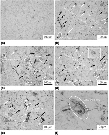
The optical micrographs of monolithic Mg and Mg–1Al–xCNTs composites are presented in Fig. 6. As shown in Fig. 6(a), the monolithic Mg was well sintered without micropores, while the initial particle boundaries could be observed. This suggested that the oxides still existed along the particle boundaries as they initially existed on the powder surface. Furthermore, these particle boundaries tended to be more obvious with the increasing weight fraction of CNTs in Mg–1Al–xCNTs composites. It can be observed from Fig. 6 that the Al-CNTs reinforcement particles are mainly distributed along the initial Mg particle boundaries and a good bonding exists between the reinforcement particles and the Mg matrix. It is noted that there are some new recrystallized grains formed in Mg–1Al–xCNTs composites, as shown in Fig. 6. For example, for Mg–1Al–0.15CNTs composites, there are new un-uniform grains (5–35 μm) appeared inside the initial Mg particles and the finer equiaxed grains (1–2 μm) formed around the reinforcements along the Mg particle boundaries, indicating that the dynamic recrystallization (DRX) took place during hot extrusion. Mg matrix is ductile and deformable while the reinforcement particle is nondeformable, so the mismatch arises between a particle and Mg matrix during deformation. Reference Deng, Wang, Zheng and Wu18 This mismatch results in the enforced strain gradient in the matrix near a particle, which causes a region with high dislocation density and large orientation gradient near a particle. Reference Doherty, Hughes, Humphreys, Jonas, Juul Jensen, Kassner, King, McNelley, McQueen and Rollett19 This region called particle deformation zone is an ideal site for development of a recrystallization nucleus. Reference Humphreys and Kalu20 Therefore, the fine DRX-grain zones are mainly located near reinforcement particles. This phenomenon is clearly observed in the Mg–1Al–0.15CNTs, Mg–1Al–0.30CNTs, and Mg–1Al–0.60CNTs composites [Figs. 6(c)–6(f)]. In addition, it can be also observed from Fig. 6 that the Al-CNTs reinforcement particles tend to cluster in the composites with the increasing weight fraction of CNTs, especially in the Mg–1Al–0.60CNTs composite [Fig. 6(d)].
Optical micrographs of (a) monolithic Mg, (b) Mg–1Al–0.08CNTs, (c) Mg–1Al–0.15CNTs, (d) Mg–1Al–0.30CNTs, (e) Mg–1Al–0.60CNTs, and (f) enlarged image of the area squared in (d), where the new grain, DRX-grain zone and cluster of Al–CNTs particles are labeled by black arrow, white arrow, and ellipse, respectively.

B. Density
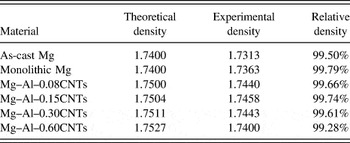
Theoretical and experimental densities of as-cast Mg, monolithic Mg, and Mg–1Al–xCNTs (x = 0.08, 0.15, 0.30, 0.60 wt%) composites are listed in Table II. As can be seen, due to the addition of Al and CNTs, the densities of Mg–1Al–xCNTs are greater than those of as-cast Mg and monolithic Mg. In addition, the experimental densities of monolithic Mg and Mg–1Al–xCNTs composites are nearly equal to their theoretical densities and the relative densities of Mg–1Al–xCNTs composites are over 99%. This indicates that SPS followed by hot extrusion is an effective technique to fabricate near-dense Mg–Al–CNTs composites.
Theoretical and experimental densities of as-cast Mg, monolithic Mg, and Mg–1Al–xCNTs (x = 0.08, 0.15, 0.30, 0.60 wt%) composites.

C. Hardness
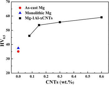
The microhardness of as-cast Mg, monolithic Mg, and Mg–1Al–xCNTs (x = 0.08, 0.15, 0.30, 0.60 wt%) composites are presented in Fig. 7. It can be seen that the microhardness of monolithic Mg fabricated by SPS followed by hot extrusion is higher than that of as-cast Mg, which might be attributed to the fact that the monolithic Mg has less defects like pores etc. than as-cast Mg. It is noted that all the Mg–1Al–xCNTs composites exhibit higher microhardness than the monolithic Mg. Furthermore, the microhardness of the Mg–1Al–xCNTs composite increases with the increasing weight fraction of CNTs particles. Compared with the monolithic Mg, the Mg–1Al–0.60CNTs composite exhibits the microhardness of 59 HV, increasing by ∼36%. The increase in microhardness can be attributed to the presence of stronger reinforcement particles distributed uniformly in the matrix, which results in higher constraint to localized matrix deformation during indentation. Reference Zhong, Wong and Gupta21–Reference Rashad, Pan, Tang, Asif and Aamir23 The formation of fine recrystallized grains (see Fig. 6) is also responsible for the increase in microhardness of Mg–1Al–xCNTs composites. Reference Eustathopoulos, Nicholas and Dreve24,Reference Gupta, Lai and Soo25
Hardness of as-cast Mg, monolithic Mg, and Mg–1Al–xCNTs (x = 0.08, 0.15, 0.30, 0.60 wt%) composites.

D. Mechanical properties
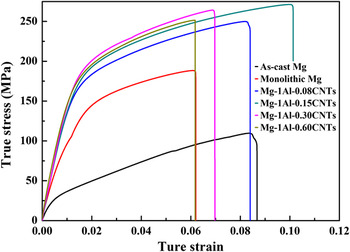
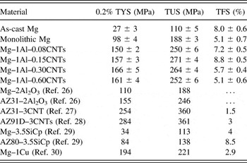
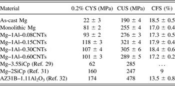
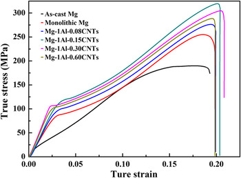
Figure 8 shows the true stress–strain curves of as-cast Mg, monolithic Mg, and Mg–1Al–xCNTs (x = 0.08, 0.15, 0.30, 0.60 wt%) composites tensiled along the ED at room temperature and the tensile mechanical properties, e.g., 0.2% TYS, tensile ultimate strength (TUS), and tensile failure strain (TFS) are summarized in Table III. Similarly, the obtained compressive true stress–strain curves are presented in Fig. 8 and the compressive mechanical properties including 0.2% CYS, compressive ultimate strength (CUS), and compressive failure strain (CFS) are listed in Table IV. As shown in Figs. 8 and 9 and listed in Tables III and IV, both the monolithic Mg and the Mg–1Al–xCNTs composites fabricated by SPS followed by hot extrusion show much better compressive mechanical properties than the as-cast Mg. Furthermore, compared with the monolithic Mg, the Mg–1Al–xCNTs composites exhibit a significant improvement in tensile and compressive strength.
Tensile true stress–strain curves of as-cast Mg, monolithic Mg, and Mg–1Al–xCNTs (x = 0.08, 0.15, 0.30, 0.60 wt%) composites.

Results of tensile testing of as-cast Mg, monolithic Mg, and Mg–1Al–xCNTs (x = 0.08, 0.15, 0.30, 0.60 wt%) composites.

Results of compressive testing of as-cast Mg, monolithic Mg, and Mg–1Al–xCNTs (x = 0.08, 0.15, 0.30, 0.60 wt%) composites.

Compressive true stress–strain curves of as-cast Mg, monolithic Mg, and Mg–1Al–xCNTs (x = 0.08, 0.15, 0.30, 0.60 wt%) composites.

Under tension, the TYS and TUS of Mg–1Al–xCNTs composites are greatly increased by the addition of Al and CNTs reinforcement particles. Among the set of the composites, the Mg–1Al–0.15CNTs composite exhibits the highest TYS (157 MPa versus 98 MPa, increased by ∼60%), TUS (271 MPa versus 188 MPa, increased by ∼44%), and TFS (5.1% versus 8.8%, increased by ∼72%) compared to the monolithic Mg. However, by further increase in the weight fraction of CNTs particles, the TFS suddenly drops and the TUS also decreases to some degree, which can be attributed to the cluster of Al-CNTs particles. Reference Habibi, Joshi and Gupta33,Reference Habibi, Joshi and Gupta34 In compression, Mg–1Al–xCNTs composites also obtain a great enhancement in CYS and CUS without reducing the CFS. As similar with the tensile mechanical properties, the Mg–1Al–0.15CNTs composite also shows the best compressive mechanical properties. Compared to the monolithic Mg, the Mg–1Al–0.15CNTs composite exhibits higher CYS (118 MPa versus 81 MPa, increased by ∼46%), CUS (321 MPa versus 255 MPa, increased by ∼26%), and a high CFS of ∼17.9%. Nevertheless, when the fraction of CNTs particles in Mg–1Al–xCNTs composites is higher 0.15%, the cluster of Al-CNTs particles also results in the CYS and CUS decreasing to a certain degree while the CFS has almost no change.
In addition, as listed in Tables III and IV, the obtained tensile and compressive mechanical properties of the composites fabricated by SPS followed by hot extrusion are more superior than some previous studies. Reference Habibnejad-Korayem, Mahmudi and Poole26–Reference Nguyen and Gupta32 It can be observed that the ductility of Mg–1Al–0.15CNTs composite is better compared with those of AZ91 and AZ31 alloys reinforced with larger fraction of CNTs. Reference Kim, Seong, Van, Ahn and Lim27,Reference Shimizu, Miki, Soga, Itoh, Todoroki, Hosono, Sakaki, Hayashi, Kim, Endo, Morimoto and Koide28,Reference Nguyen and Gupta32 The Mg–1Al–0.15CNTs composite shows higher strength and ductility than Mg and its alloys reinforced with high fraction of other particles (Al2O3, SiC, and Cu). Reference Habibnejad-Korayem, Mahmudi and Poole26,Reference Matin, Saniee and Abedi29–Reference Das and Harimkar31 The present study indicated that the addition of 1% Al and the low weight fraction of CNTs were extremely advantageous to the improved mechanical properties of Mg–1Al–xCNTs composites. Furthermore, the low weight fraction of expensive CNTs does not significantly increase the cost and density of the Mg-based composites. This comparison reveals that the Mg–1Al–xCNTs composites with better comprehensive mechanical properties are developed by SPS followed by hot extrusion in the current study.
The improved strength of Mg–1Al–xCNTs composites (x = 0.08, 0.15, 0.30, 0.60 wt%) can be attributed to: (a) Hall–Petch strengthening; (b) Orowan strengthening; (c) the elastic modulus mismatch and the coefficient of thermal expansion (CTE) mismatch strengthening; and (d) load transfer strengthening.
The DRX occurred in the Mg–1Al–xCNTs composites during hot extrusion leads to the appearance of fine un-uniform grains and finer DRX-grain zones, as shown in Fig. 6. According to the Hall–Petch relationship Reference Sanaty-Zadeh35 : σy = σ0 + K y d −1/2 (σy is the yield strength, σ0 and K y are constants relating to the material, and d is the grain size), the fine grains where the motion of dislocations across the grain boundary is hindered lead to the increasing yield strength in the material.
Orowan looping, Reference Zhang and Chen36 which is caused by the hindered movements of the dislocations due to the insertion of submicron or nanoscale particles, also plays an important role in strengthening. The formation of residual dislocation loops around each particle due to the addition of reinforcement particles will produce a back stress that impedes dislocation migration, thus resulting in an increase in the yield strength. Reference Rashad, Pan, Tang, Asif, Hussain, Gou and Mao37 ∆σOrowan can be described by the Orowan–Ashby equation Reference Aikin and Christodoulou38 :
 $$\Delta {\sigma _{{\rm{Orowan}}}} = {{0.13{G_{\rm{m}}}b\,\ln \left( {{{{d_{\rm{p}}}} \mathord{\left/ {\vphantom {{{d_{\rm{p}}}} {2b}}} \right. \kern-\nulldelimiterspace} {2b}}} \right)} \over \lambda }\quad ,$$
where G m represents the shear modulus of the matrix (1.66 × 10⁴ MPa for Mg); b is the Burgers vector of the matrix (3.21 × 10⁻¹⁰ m for Mg); d p is the mean particle size, and λ is the interparticle spacing, expressed as follows Reference Zhang and Chen39,Reference Meyers and Chawla40 :
 $$\lambda \approx {d_{\rm{p}}}\left[ {{{\left( {{1 \over {2{V_{\rm{p}}}}}} \right)}^{{1 \mathord{\left/ {\vphantom {1 3}} \right. \kern-\nulldelimiterspace} 3}}} - 1} \right]\quad .$$
The CTE for Mg, Al, and CNTs is 25 × 10−6 K−1, 23.6 × 10⁻⁶ K−1, and 2.7 × 10⁻⁶ K−1, respectively. In addition, the elastic modulus is 40–45 GPa for Mg and 69.6 GPa for Al. Reference Clyne and Withers41 The elastic modulus for single and bilayer graphene is 2.4 ± 0.4 and 2.0 ± 0.5 TPa, respectively. Reference Lee, Yoon and Cheong42 Therefore, there are large differences in the CTE and elastic modulus between the Mg matrix and Al-CNTs reinforcement particles, which results in dislocation generation in the vicinity of the interface. The pile up of these dislocations at the interface leads to the improved strength of Mg–1Al–xCNTs composites. Reference Száraz, Trojanová, Cabbibo and Evangelista43,Reference Dai, Ling and Bai44 The CTE mismatch between the matrix Mg and Al-CNTs reinforcement particles results in an increase in yield strength of the composites, ∆σCTE can be estimated using the following equation Reference Miller and Humphreys45 :
 $$\Delta {\sigma _{{\rm{CTE}}}} = \alpha Gb\sqrt {{{12\Delta T\Delta C{f_{\rm{\nu }}}} \over {b{d_{\rm{p}}}}}} \quad ,$$
where ∆σCTE is the change of yield strength resulting from CTE; α is a constant (1.25); G is the shear modulus of Mg matrix (1.66 × 10⁴ MPa); b is the Burgers vector of matrix (3.21 × 10⁻¹⁰ m for Mg) Reference Frost and Ashby46 ; ∆T is the change of temperature; ∆C is the difference in the CTE between matrix and reinforcement; f ν is the volume fraction of particles; and d p is the mean particle size.
Good interfacial bonding between the matrix and the reinforcement particles by interfacial shear stress mainly determines the load transfer from the matrix to reinforcement particles. It can be seen from x-ray mapping results in Fig. 5 that the Al-CNTs particles are distributed uniformly in the Mg matrix, which results in the efficient load transfer from the matrix to reinforcement particles, thus leading to the improved strength of the composites. A shear lag equation can be used to explain the strengthening produced by load transfer from the matrix to reinforcement particles, the increase in yield strength of composites due to the load transfer can be given using the following equation Reference Clyne and Withers41,Reference Luster, Thumann and Baumann47 :
 $$\Delta {\sigma _{{\rm{LT}}}} = {{{f_{\rm{v}}}{\sigma _{\rm{m}}}} \over 2}\quad ,$$
where △σLT represents the increase in the yield strength, f ν is the volume fraction of particles, and σm is the yield strength of the matrix.
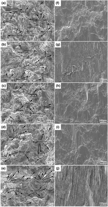
The tensile and compressive fracture surface characterization of monolithic Mg and Mg–1Al–xCNTs (x = 0.08, 0.15, 0.30, 0.60 wt%) composites are shown in Fig. 10. It is clear from the SEM tensile fracture images that the monolithic Mg and Mg–1Al–xCNTs composites show brittle fracture, which is due to the limited slip systems in Mg with hcp structure. Reference Reed-Hill and Robertson48 In addition, it is noted that different numbers of microcracks are distributed in the tensile fracture surfaces of monolithic Mg and Mg–1Al–xCNTs composites (Fig. 10), which means a poor plasticity. However, as shown in Fig. 9(c), the tensile fracture image of Mg–1Al–0.15CNTs composite exhibits some small dimple-like features dimple and less microcracks, indicating an enhancement of plasticity. As seen from Fig. 10, the compressive fracture images of monolithic Mg and Mg–1Al–xCNTs composites show almost similar characteristics without microcracks, indicating that they have similar CFS (see Table IV).
Tensile (left) and compressive (right) fracture surface images of composites: (a) (f) monolithic Mg, (b) (g) Mg–1Al–0.08CNTs, (c) (h) Mg–1Al–0.15CNTs, (d) (i) Mg–1Al–0.3CNTs and (e) (j) Mg–1Al–0.6CNTs.

IV. CONCLUSION
In the present study, near-dense Mg–1Al–xCNTs (x = 0.08, 0.15, 0.30, 0.60 wt%) composites were successfully fabricated by SPS followed by hot extrusion. The composites showed a significant improvement in tensile and compressive properties compared to the monolithic Mg. Especially the Mg–1Al–0.15CNTs composite exhibited the best mechanical properties among the fabricated composites. Compared with the monolithic Mg, the Mg–1Al–0.15CNTs composite exhibited higher TYS (157 MPa versus 98 MPa, increased by ∼60%), TUS (271 MPa versus 188 MPa, increased by ∼44%), CYS (118 MPa versus 81 MPa, increased by ∼46%), and CUS (321 MPa versus 255 MPa, increased by ∼26%), and maintained a high TFS of ∼8.8% and a high CFS of ∼17.9%. It can be considered that Hall–Petch strengthening, Orowan strengthening, CTE, and elastic modulus mismatches strengthening and load transfer strengthening collectively lead to the significant enhancement in tensile and compressive strength of the Mg–1Al–xCNTs composites.
ACKNOWLEDGMENTS
The authors thank Program for National Natural Science Foundation of China (51504162), Natural Science Foundation of Shanxi Province (2015021073, 2015011033), Scientific and Technological Innovation Programs of Higher Education Institutions in Shanxi (2014118), Scientific Activities of Selected Returned Overseas Professionals in Shanxi Province (2014), Special/Youth Foundation of Taiyuan University of Technology (2014TD016), Shanxi Province Fundamental Resources Platform of Science and Technology (201605D121030) and Scientific and Technological Innovation Programs for Excellent Researchers in Shanxi Province (201605D211015) for their financial supports.