I. INTRODUCTION
Fuel cells are promising candidates for alternative energy sources. New materials need to be developed to achieve further advances in fuel cell technology. One such material is the Nafion membrane (Dupont, Wilmington, DE) used in polymer electrolyte fuel cells (PEFCs). A PEFC membrane is a proton-conducting polymeric film that acts as a gas barrier as well as a proton conductor. For practical applications, PEFC membranes should have not only good proton conductivity, but also high long-term stability, thermal stability, and mechanical stability. Nafion polymers have low thermal stability and proton conductivity at intermediate temperatures (100–150 °C).
To resolve the aforementioned problems, several authors have developed polymersReference Pereira, Felisberti and Rocco1–Reference Yamada and Honma5 and organic–inorganic hybridsReference Onizuka, Kato, Shimura, Sakamoto and Yogo6, Reference Yazawa, Shojo, Mineshige, Yusa, Kobune and Kuraoka7 by the polymerization and/or condensation of vinylphosphonic acid (VPA). However, organic polymers are generally thermally unstable at intermediate temperatures. The sol-gel method is usually employed to fabricate organic–inorganic hybrids. In this method, it is necessary to remove solvents such as water and alcohol after membrane formation. In some cases, therefore, it is not easy to obtain monolithic materials or large membranes because of crack formation during solvent evaporation.Reference Brinker and Scherer8 Moreover, because several types of reactant are present in the solvent, and hydrolysis and condensation occur simultaneously, it is difficult to obtain the desired structure.
Recently, another synthesis route for organic–inorganic hybrids, involving solventless reactions using orthophosphoric acid and organically modified silanes, has been developed;Reference Niida, Takahashi, Uchino and Yoko9–Reference Tokuda, Tanaka, Takahashi, Ihara and Yoko15 the following metathesis occurs on heating: Si–X + P–OH → Si–O–P + HX↑ (X = Cl, ethoxy). Groups that do not participate in this reaction are omitted from the reaction formula. For example, (CH3)2SiX2 + H3PO4 → (CH3)2XSiOP(OH)2O + HX↑ is abbreviated to Si–X + P–OH → Si–O–P + HX↑. This reaction proceeds with traces of HX because the reaction temperature is near/above the boiling point of HX. Because of the absence of solvent evaporation, a transparent, crack-free, large, hybrid monolith can be produced simply by mixing the starting reagents, followed by heat treatment.
The hybrids prepared by metathesis contained an almost complete alternating copolymer consisting of silicate and phosphite units, Si–O–P. In this way, it is possible to achieve structure manufacturing. The phosphole group (POH) of VPA is required for high proton conductivity; however, excess VPA is expected to decrease the chemical durability of the hybrids. The present alternating copolymerization of oxides will enable the preparation of a new group of materials having high proton conductivity and good chemical durability and thermal stability because they will enable formation of a proton-conducting path with a lot of phosphole groups.
In this study, we design another class of proton-conducting organic–inorganic silicophosphite membranes based on solventless ethanol condensation followed by polymerization. We also carry out structural analyses using 29Si and 31P nuclear magnetic resonance (NMR) to confirm the occurrence of copolymerization, because few reports have been published on silicophosphite network formation by solventless ethanol condensation.Reference Tokuda, Tanaka, Takahashi, Ihara and Yoko15, Reference Lorenzo, Esquivias, Barboux, Maquet and Taulelle16 The thermal stability, durability, and proton conductivity of the membranes are also investigated.
II. EXPERIMENTAL
A. Preparation of organic–inorganic hybrid silicophosphite membrane
Vinylphosphonic acid (VPA; Tokyo Chemical Industry, Tokyo, Japan), diethoxymethylvinylsilane (DEMVS; Shin-Etsu Silicones, Tokyo, Japan), 3-methacryloxypropyldiethoxysilane (MDEMS; Shin-Etsu Silicones), anhydrous orthophosphoric acid (PA, crystal purity 99%; Merck, Whitehouse Station, NJ), and a polymerization initiator, Irgacure 754 (Ciba; Basel, Switzerland), were used. SILBEST No. 8560 (Tokuriki Chemical Research, Tokyo, Japan) was used as an electrically conductive adhesive for performing electrical conductivity measurements. VPA and DEMVS were stirred for 60 min at 90 °C under a N2 atmosphere. MDEMS was then added, and the resulting mixture was stirred for 30 min at 90 °C under a N2 atmosphere. A viscous precursor was obtained. PA was mixed with this precursor if required, and 0.3 wt% Irgacure 754 was then added to the precursor and the resulting mixture was poured into a polydimethylsiloxane mold. This mixture was irradiated using a high-pressure mercury lamp (UI-501C, Ushio, Tokyo, Japan) for 60 min with an irradiance of 120 mW/cm2, along with heat treatment at 100 °C.
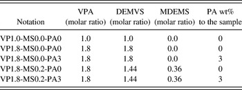
The sample compositions were designated using the starting material composition as follows: VP is the ratio of VPA to organically modified silanes, MS is the mol fraction of MDEMS with respect to silanes, and PA represents the PA weight% in the sample; for example, precursor VP1.8-MS0.2-PA3 refers to a precursor in which VPA:DEMVS:MDEMS = 1.8:0.8:0.2, including 3 wt% PA. The sample notations are listed in Table I.
Sample notation in this study. VPA, DEMVS, MDEMS, and PA are vinylphosphonic acid, diethoxymethylvinylsilane, 3-methacryloxypropyldiethoxysilane, and anhydrous orthophosphoric acid, respectively.

For the NMR assignments, DEMVS was hydrolyzed and condensed using HCl, water, and ethanol. VPA was also condensed at 200 °C.
B. Characterization
Structural analyses were performed using a 29Si and 31P NMR spectrometer (JEOL, CMX 400, Tokyo, Japan). The 90° pulses of 29Si and 31P were 4 and 3 μs, respectively. The delay times were set to 15 and 10 s for 29Si and 31P NMR, respectively. The chemical shifts were expressed in ppm with respect to tetramethylsilane for 29Si (0 ppm) and phosphoric acid for 31P (0 ppm). Attenuated total-reflectance infrared spectroscopy (ATR-IR; Thermo Nicolet Avatar360, Thermo Nicolet, Madison, WI) was also performed. Thermal stabilities were characterized by thermogravimetry (TG; Rigaku TG 8120, Rigaku, Tokyo, Japan) at a heating rate of 5 °C/min, and thermal mechanical analysis (TMA; Rigaku TMA 8310) at a heating rate of 10 °C/min.
For electrical conductivity measurements, the samples were coated with an electrically conductive adhesive (SILBEST No. 8560), and a Pt wire was used as an electrically conductive lead. The electrical conductivity was measured by frequency response analysis of the impedance spectra (Solartron 1255B and SI 1287, AMETEK, Hampshire, UK). The applied amplitude and alternating current (ac) frequency range were 100 mV and 1 mHz to 1 MHz, respectively. Humidity–temperature control was performed using SH-221 or SH-240 (ESPEC, Hudsonville, MI). To equilibrate the water content in the membrane, the membrane was placed inside the chamber for 6–12 h after a temperature change. To ensure equilibrium, the measurements were repeated several times until no changes were observed in the spectra.
For chemical durability estimations, we captured images of the membranes placed in the chamber for 72 h at room temperature and 40% relative humidity (RH). It is difficult to estimate the durability by weight loss because of water absorption. We have therefore provided qualitative durability estimation data in this study.
III. RESULTS
A. NMR analyses
The precursors were viscous, homogeneous, transparent liquids. The final products, after irradiation with ultraviolet (UV) light, were transparent, homogeneous, colorless, crack-free, large, water-durable, flexible membranes (Fig. 1).
Photograph of hybrid VP1.8-MS0.0-PA0. Large, crack-free membranes were obtained.

The precursors and hybrids exhibited several types of bonding, such as Si–O–P, Si–O–Si, and P–O–H. In this context, the following abbreviations are used. Dn* refers to Si with n Si–O–P bondings and (2 – n) ethoxides, and Dn refers to n Si–O–Si bondings with (2 – n) ethoxides. Tn* refers to P in VPA with n P–O–Si bondings and (3 – n) phospholes, and Tn refers to n P–O–P bondings. Qn* refers to P in added PA with n Si–O–P bondings and (3 – n) phospholes. The symbols with an asterisk denote species having alternating copolymers consisting of silicate and phosphite units, and those without an asterisk denote a self-condensed polymer structure.
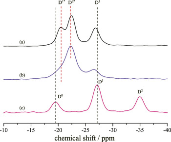
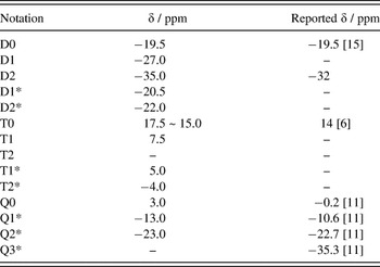
The 29Si NMR spectra of the precursors (a) VP1.0-MS0.0-PA0, (b) VP1.8-MS0.0-PA0, and (c) partially condensed DEMVS are shown in Fig. 2. The spectra observed in this study were normalized, as their areas are equal to each other. The peaks at −19.5, −27.0, and −35.0 ppm [shown in Fig. 2(c)] are attributed to D0, D1, and D2, respectively, because the precursor prepared by hydrolyzing DEMVS is composed only of these respective species, which are generated by self-condensation. These assignments are in agreement with those reported in a previous study.Reference Olejniczak, Łączka, Cholewa-Kowalska, Wojtach, Rokita and Mozgawa17 Next, we focus on the additional peaks at −20.5 and −22.0 ppm shown in Figs. 2(a) and 2(b). These peaks relate to Si–O–P bonding because they appeared only if VPA was added to the precursors. In addition, the intensity of the peak at −20.5 ppm decreased and the intensity at −22.0 ppm increased with increasing VPA. We therefore assigned the peaks at −20.5 and −22.0 ppm to D1* and D2*, respectively.
29Si NMR spectra of precursors (a) VP1.0-MS0.0-PA0, (b) VP1.8-MS0.0-PA0, and (c) partially condensed DEMVS.

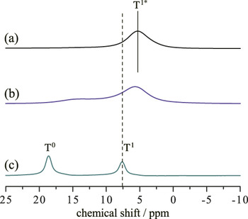
Figure 3 shows the 31P NMR spectra of precursors (a) VP1.0-MS0.0-PA0, (b) VP1.8-MS0.0-PA0, and (c) partially condensed VPA. Two peaks were observed in the case of partially condensed VPA, at 17.5 and 7.5 ppm, which are assigned to T0 and T1, respectively. This is because the partially condensed VPA is composed of only T0 and T1, even though vinyl group polymerization also occurs. A previous study reported that T0 appeared at around 14 ppm.Reference Onizuka, Kato, Shimura, Sakamoto and Yogo6 This discrepancy may be due to vinyl polymerization or a solvation effect. Our experiments were performed under solventless conditions, but previous studies used a solvent, which would affect the density and viscosity of the mixture. This may change the magnetic permeability of the solvent and the 31P chemical shifts. In addition, the peak at 5.0 ppm for precursor VP1.0-MS0.0-PA0 [shown in Fig. 3(a)] is assigned to T1* because the 29Si NMR spectra shown in Fig. 2(a) reveal that the present precursor includes an alternating copolymerized structure, such as Si–O–P, producing T1*. The downfield shift relative to T1* at 15.0 ppm for precursor VP1.8-MS0.0-PA0 [shown in Fig. 3(b)] is also assigned to T0 because it contains more VPA than precursor VP1.0-MS0.0-PA0. Here, the solvation effect is attributed to the high-field shift of T0 from VPA.
31P NMR spectra of precursors (a) VP1.0-MS0.0-PA0, (b) VP1.8-MS0.0-PA0, and (c) partially condensed VPA.

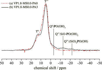
To clarify the effect of the addition of PA, 31P NMR spectra of the precursors VP1.8-MS0.0-PA0 and VP1.8-MS0.0-PA3 are also shown in Fig. 4; the spectra are normalized because the areas corresponding to VPA are equal. An increase in T0 and a decrease in T1* were observed after addition of PA. Small peaks assigned to Q0, Q1*, and Q2* appeared at −3.0, −13.0, and −23.0 ppm.Reference Megumi, Takahashi, Tokuda and Yoko13 The assignments of all the peaks are listed in Table II.

Assignment of the peaks in 29Si and 31P NMR spectra. Dn* refers to Si with n Si–O–P bondings and (2 – n) ethoxy groups, and Dn refers to n Si–O–Si bondings with (2 – n) ethoxy groups. Tn* refers to P in VPA with n P–O–Si bondings and (3 – n) phospholes, and Tn refers to n P–O–P bondings. Qn* refers to P in added PA with n Si–O–P bondings and (3 – n) phospholes. The symbols with an asterisk denote species having alternating copolymers consisting of silicate and phosphite units, while those without an asterisk denote a self-condensed polymer structure.

B. IR analyses
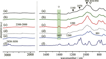
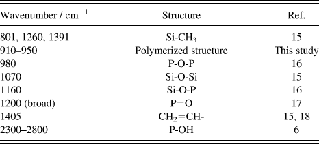
The IR spectra of (a) hybrid VP1.8-MS0.0-PA0, (b) hybrid VP1.8-MS0.0-PA3, (c) precursor VP1.8-MS0.0-PA0, (d) hybrid VP1.8-MS0.2-PA0, (e) VPA as a reagent, and (f) DEMVS as a reagent are shown in Fig. 5. The absorption at 1260 cm−1, related to Si–CH3,Reference Olejniczak, Łączka, Cholewa-Kowalska, Wojtach, Rokita and Mozgawa17 remained unchanged during polymerization. The IR spectra were therefore normalized with respect to the Si–CH3 absorption. From the literature, the absorptions at 980, 1070, 1160, 1200 (broad), 1405, and 2300–2800 (broad) cm−1 are assigned to P–O–P,Reference Kannan, Choudhury and Dutta18 Si–O–Si,Reference Olejniczak, Łączka, Cholewa-Kowalska, Wojtach, Rokita and Mozgawa17 Si–O–P,Reference Kannan, Choudhury and Dutta18 P=O,Reference Colthup, Daly and Wiberley19 CH2=CH (vinyl),Reference Olejniczak, Łączka, Cholewa-Kowalska, Wojtach, Rokita and Mozgawa17, Reference Förner and Badawi20 and POH,Reference Onizuka, Kato, Shimura, Sakamoto and Yogo6 respectively. The peaks at 801 and 1391 cm−1 are also assigned to Si–CH3.Reference Olejniczak, Łączka, Cholewa-Kowalska, Wojtach, Rokita and Mozgawa17 The differences in the IR spectra before and after UV irradiation were a decrease at 1405 cm−1 (vinyl) and an increase at 910–950 cm−1. The absorptions at around 910–950 cm−1 are thus assigned to the polymerized structure. These values are also listed in Table III. The symbols ▼, ◊, and ∇ in Fig. 5 refer to the inorganic structure, polymerized structure, and vinyl group, respectively. Unlike the 31P NMR spectra, there was no apparent difference between the IR spectra of the precursors VP1.8-MS0.2-PA3 and VP1.8-MS0.2-PA0.
Fourier transform infrared spectra of (a) hybrid VP1.8-MS0.0-PA0, (b) hybrid VP1.8-MS0.0-PA3, (c) precursor VP1.8-MS0.0-PA0, (d) hybrid VP1.8-MS0.2-PA0, (e)VPA as reagent, and (f) DEMVS as reagent.

Assignment of the absorptions in IR spectra.

C. Thermal mechanical analyses
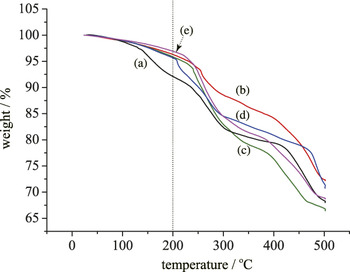
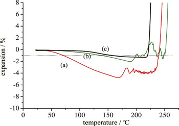
Figure 6 shows TG curves of hybrid membranes of (a) VP1.0-MS0.0-PA0, (b) VP1.8-MS0.0-PA0, (c) VP1.8-MS0.2-PA0, (d) VP1.8-MS0.0-PA3, and (e) VP1.8-MS0.2-PA3. It was observed that weight loss from the membranes proceeded in three steps: (i) below 100 °C, (ii) between 100 and 200 °C, and (iii) above 200 °C. Hybrids (b)–(e) were thermally stable up to 200 °C, whereas hybrid (a) was unstable. Figure 7 shows TMA curves of hybrid membranes of (a) VP1.8-MS0.0-PA0, (b) VP1.8-MS0.2-PA0, and (c) VP1.8-MS0.2-PA3. For the sake of convenience, the thermally mechanical stable temperature, Ts, is defined as the temperature at which 1% shrinkage occurs, to simplify comparison of the values. The values for hybrids (a)–(c) were 72, 143, and 162 °C, respectively.
TG curves of hybrids (a) VP1.0-MS0.0-PA0, (b) VP1.8-MS0.0-PA0, (c) VP1.8-MS0.2-PA0, (d) VP1.8-MS0.0-PA3, and (e) VP1.8-MS0.2-PA3. Measurements were performed in air at a heating rate of 10 C/min. The dashed line provides a visual guide.

TMA curves of hybrids (a) VP1.8-MS0.0-PA0, (b) VP1.8-MS0.2-PA0, and (c) VP1.8-MS0.2-PA3. Measurements were performed in air at a heating ratio of 10 K/min. Inset: dashed line indicates 1% shrinkage.

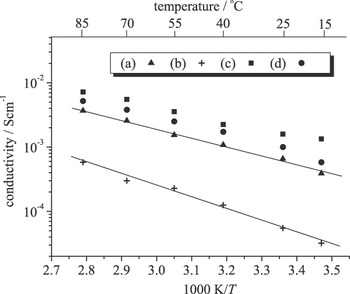
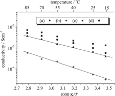
Figure 8 shows the temperature dependence of the electrical conductivities of hybrids (a) VP1.8-MS0.0-PA0, (b) VP1.8-MS0.2-PA0, (c) VP1.8-MS0.0-PA3, and (d) VP1.8-MS0.2-PA3 under 80% RH. The electrical conductivities at 85 °C under 80% RH were 3.6 × 10⁻³, 5.8 × 10⁻⁴, 7.2 × 10⁻³, and 5.2 × 10⁻³ S/cm for hybrids (a) VP1.8-MS0.0-PA0, (b) VP1.8-MS0.2-PA0, (c) VP1.8-MS0.0-PA3, and (d) VP1.8-MS0.2-PA3, respectively.
Temperature dependence of conductivities for membranes under 80% RH conditions; hybrids (a) VP1.8-MS0.0-PA0, (b) VP1.8-MS0.2-PA0, (c) VP1.8-MS0.0-PA3, and (d) VP1.8-MS0.2-PA3.

D. Chemical durability
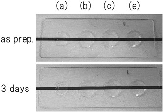
Figure 9 shows photographs taken before and after chemical durability estimations: (a) VP1.0-MS0.0-PA0, (b) VP1.8-MS0.0-PA0, (c) VP1.8-MS0.2-PA0, and (e) VP1.8-MS0.2-PA3. Cracks formed in sample (a) and phosphonic acid was eluted from samples (a) and (b). Crack formation and phosphonic acid elution were not observed in samples (c) and (d).
Photographs before and after durability estimation. (a) VP1.0-MS0.0-PA0, (b) VP1.8-MS0.0-PA0, (c) VP1.8-MS0.2-PA0, and (d) VP1.8-MS0.2-PA3. Cracks formed in sample (a), and phosphonic acid was eluted from samples (a) and (b).

IV. DISCUSSION
A. Structural analyses
The present authors have proposed the following alcohol condensation mechanism for orthophosphoric acid and organically modified alkoxysilanes in a solventless reactionReference Tokuda, Tanaka, Takahashi, Ihara and Yoko15:


As shown in Figs. 2 and 3, the presence of D1*, D2*, and T1* in the precursor indicates that such condensations proceed during the precursor formation process. Reactions (1)–(3) represent the main reaction path because the areas related to the alternating copolymer, Si–O–P, are larger than those related to the self-condensed polymers, Si–O–Si or P–O–P.
D1 is produced as a result of the following side reaction:


where H2O is supplied by the dehydrating condensation of VPA:

or by contaminated water in VPA. In reactions (5) and (6), it is assumed that ethanol evaporates easily, but H2O does not, because the precursors are heated at 90 °C; however, there is a trace of ethanol in the system. In fact, the viscosity of the precursor is high in an open system (present study), but remains low in a closed reaction system (not shown). This observation supports ethanol evaporation during the reaction. Reactions (1) and (2) also indicate that the reaction proceeds step-by-step because the acid dissociation constants, pKa1 and pKa2, of VPA in water are 1.1 and 6.6, respectively, although in the solventless reaction, the dissociation constants of the two types of phosphole are predicted to be different from those in water.
Thus, Si–O–P bonding is mainly formed by the ethanol condensation reaction, and Si–O–Si and P–O–P bondings are formed as by-products. On the other hand, in the conventional sol-gel method, Si–O–P bondings are formed as by-products because the rate of polycondensation between silicon alkoxide and phosphonic acid is different. One of the advantages of this method is that phosphonic acid can be easily stabilized in the membrane. In addition, all the P atoms in precursors VP1.0-MS0.0-PA0 and VP1.8-MS0.0-PA0 have phosphole as a proton donor because they are not D2 or D2*, but D1 or D1*.
In the case of the addition of PA, Q1* and Q2* are produced, as described in Sec. III. A (Fig. 4), which indicates that PA was stabilized in the precursor by reacting with the silanol in DEVMS. On the other hand, a decrease in T1* and an increase in T0 were also observed. This is because PA consumes some of the silanols, reducing reaction between VPA and silanol
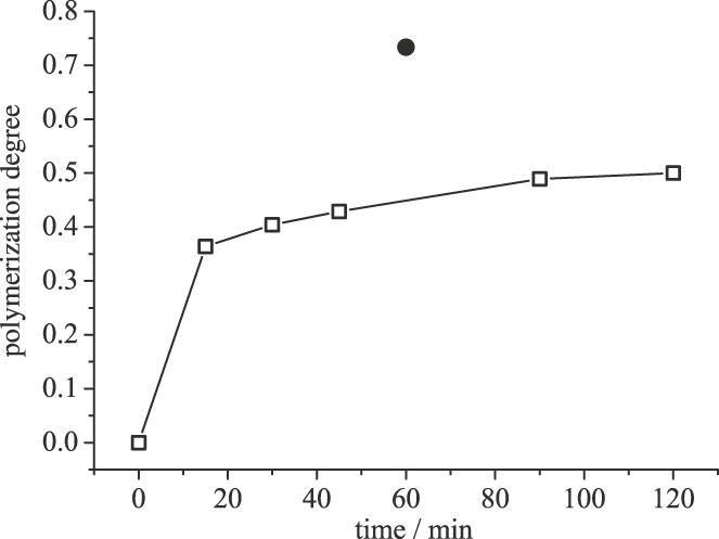
In the IR spectra (Fig. 5), the absorption at 1405 cm−1 related to the vinyl group decreases after UV irradiation. The polymerization degree can be calculated as

where A(t) is the area of the vinyl group absorption at time t (Fig. 10). It should be noted that the absorption at 1391 cm−1 related to Si–CH3 overlaps the vinyl group absorption. Thus, the maximum polymerization degree is not equal to 1. The polymerization rate is high immediately after UV irradiation and low after 10 min. Consequently, the membranes for characterization were obtained by UV irradiation for 60 min with heat treatment to ensure complete polymerization and to reduce the reaction time. The polymerization degree for this hybrid was 0.73, as shown in Fig. 10 (closed circle).
Polymerization degree plotted against UV irradiation time. The open square, ▫, denotes polymerization without heat treatment, and the closed circle, •, denotes polymerization with heat treatment at 60 °C.

In the case of the addition of PA, no specific IR spectral change was observed [Figs. 5(a) and 5(b)], although the NMR spectrum was affected (Fig. 4). When PA is introduced into the precursor, it produces P–OH, P=O, and P–O–Si bondings. However, the amount of PA added is small, and these peaks are broad, so they do not cause a change in the IR spectra.
As described here, it is possible to design organic–inorganic hybrid silicophosphite networks using a solventless reaction. This can be achieved by the following steps: (i) creation of an inorganic alternating copolymer structure, Si–O–P, and control of the residual phosphole; (ii) functionalization by addition of PA, if required; and (iii) formation of an organic polymer structure by photopolymerization or thermal polymerization. Moreover, metal alkoxides can be introduced into the hybrids, instead of silicon alkoxides, to introduce new functionalities (not shown).
B. Thermal and chemical stability of membranes
In this section, we discuss the thermal stability in the intermediate temperature region (100–200 °C). TGA results indicated that the series of hybrids having P/Si = 1.8 exhibit good thermal stability below 200 °C, whereas the hybrid VP1.0-MS0.0-PA0 does not. The 29Si NMR spectra shown in Fig. 2 indicate that the hybrid VP1.0-MS0.0-PA0 contains more Si–OEt and Si–OH as D1* and D1 than the hybrid VP1.8-MS0.0-PA0 does. These groups react with each other below 150 °C to release water and/or ethanol, resulting in low thermal stability. In contrast, replacement of DEMVS with MDEMS does not affect the thermal stability, as shown in Figs. 6(c) and 6(e). These facts indicate that the thermal stability depends not on the organic network but on the inorganic residual group.
It was observed from the TMA curves that addition of DEMVS improves the thermal mechanical stabilities. The Ts values for the hybrids with DEMVS [Figs. 7(b) and 7(c)] are higher than those of the hybrids without DEMVS [Fig. 7(a)], although no difference was observed in TGA below 200 °C for these hybrids. Moreover, it was revealed that the addition of PA improves the thermal mechanical stabilities up to almost 218 °C (1.3% shrinkage). Thus, the thermal mechanical stability depends on both the inorganic and organic networks.
The durabilities of the membranes were improved, as shown for samples (c) VP1.8-MS0.2-PA0 and (e) VP1.8-MS0.2-PA3. These membranes were stable in moderate atmospheric conditions because of stabilization of the inorganic network, but the membrane made from polyvinylphosphonic acid swells easily. However, under extreme atmospheric conditions, the present membranes swell. Thus, the durability achieved is still not sufficient, and we need to improve it further.
C. Electrical conductivity of hybrids
In all these hybrids, the conductivity depends linearly on 1/T. The activation energy, E a, can therefore be written as follows:

where σ, A, and R are the electrical conductivity, frequency factor, and gas constant, respectively. The activation energies for the present hybrids were calculated as 21 kJ/mol, which indicate that proton conduction is based on the Grotthus mechanism.Reference Coloban and Novak21
A comparison of Fig. 8(a) with Fig. 8(b) indicates that the replacement of DEMVS with MDEMS decreases the conductivity, although the number of OH groups in hybrid (a) VP1.8-MS0.0-PA0 is almost the same as that in hybrid (b) VP1.8-MS0.2-PA0, as shown in Figs. 5(a) and 5(d), respectively. One possible reason for the impedance decrement is proton trapping on the acrylic group. In contrast, addition of a small amount of PA effectively increases the conductivity, as shown in Fig. 8; the conductivities of the hybrids VP1.8-MS0.0-PA3 and VP1.8-MS0.2-PA3 were 7.2 × 10⁻³ and 5.2 × 10⁻³ S/cm, respectively. This is because PA acts as a proton donor and introduces a proton-conducting path into the membrane.
As described in Sec. III. C, VP1.8-MS0.2-PA3 is stable up to 218 °C. This membrane is also durable in moderate atmospheres. This membrane is therefore a potential candidate for highly proton conductive materials with good thermal stability.
V. CONCLUSION
To fabricate a proton-conducting membrane for fuel cells, organic–inorganic hybrid silicophosphites were prepared by alcohol condensation under solventless, catalyst-free, low-temperature, one-pot conditions. The resultant material was a transparent, homogeneous, colorless, crack-free, large, flexible membrane. We also investigated the local structures of the resulting membranes using 29Si and 31P NMR spectroscopy and IR measurements. The reaction resulted in inorganic alternating copolymerization, i.e., Si–O–P formation, for the most part, although self-condensation, i.e., Si–O–Si or P–O–P formation, also occurred. It was also observed that all P atoms have a phosphole as a proton donor. Subsequent UV irradiation with heat treatment led to formation of a polymerization structure that connected the inorganic alternating copolymers with each other. The thermal stability was also investigated by TGA and TMA. It was found that hybrid VP1.8-MS0.2-PA3 is stable in the intermediate-temperature range (100–220 °C). The durability was also investigated qualitatively. It was found that the durability of the hybrid VP1.8-MS0.2-PA3 was improved, but further improvement is still required. The proton conductivity of the hybrids was evaluated to be 5.2 × 10⁻³ S/cm. Thus, this synthesis route can be used to establish structure manufacturing and to develop a new group of materials for applications in fuel cells.
ACKNOWLEDGMENTS
This work was financially supported by the Joint Project of Chemical Synthesis Core Research Institutions Research and Education Funding for inter-University Research Projects, MEXT, Japan, and partially supported by a Grant-in-Aid for Scientific Research, No. 20613007, and Exploratory Research and Mission Research Project for Sustainable Humanosphere Science, Kyoto University. This work is also supported by Grant-in-Aid for Scientific Research (C), No. 20613007, MEXT. One of the authors (Y.T.) acknowledges financial support from the Murata Science Foundation.