

I. INTRODUCTION
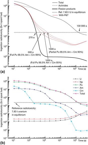
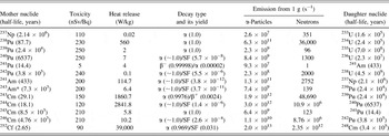
One of the major challenges of the back-end of the nuclear fuel cycle is to determine the fate of actinides that are either separated during reprocessing or remain, in minor amounts, in the high-level waste (HLW) generated by reprocessing. Reprocessing of one metric tonne (mt) of spent nuclear fuel (SNF) yields up to 13 m3 of liquid HLW Reference Kopyrin, Karelin and Karelin1 containing a total of up to 0.4 kg/m3 residual U, Pu and minor actinides, MA (MA = Np, Am, Cm). These elements emerge as major contributors to the long-time ecological hazard (Fig. 1). 2–4 The dose factors for the most dangerous fission products, 135Cs and 90Sr, are estimated to be 13 and 28 nSv/Bq, respectively, with the highest value of 110 nSv/Bq for 129I, Reference Eckerman, Harrison, Menzel and Clement5 but thereafter, the dose is between 110 and 250 nSv/Bq and is dominated by the actinide contribution (Table I and Refs. 4–7). To prevent the release of actinides, a possible strategy is to incorporate actinides in durable crystalline solids that are suitable for disposal in a geologic repository or in very deep boreholes. Reference von Hippel, Ewing, Garwin and Macfarlane8–Reference Laverov, Velichkin, Omelyanenko, Yudintsev, Petrov and Bychkov11 Currently, alumino-phosphate (in Russia) and borosilicate glasses (USA, France, UK, Germany, Japan, India, PRC) are used. However, the vitreous state is thermodynamically metastable, and vitreous waste forms may devitrify, which is enhanced at elevated temperature and in an ionizing radiation field. Reference Lutze and Ewing9–Reference Laverov, Velichkin, Omelyanenko, Yudintsev, Petrov and Bychkov11 Additionally, the interaction of glass surfaces with underground waters and brines can produce colloids Reference Pierce, McGrail, Martin, Marra, Arey and Geiszler12,Reference Novikov, Kalymkov, Utsunomiya, Ewing, Horreard, Merkulov, Clark, Tkachev and Myasoedov13 that facilitate the transport of actinides over long distances. Ceramic waste forms are essentially more suitable for the safe immobilization of transuranium actinides.


A key consideration in the development of any actinide waste form is the effect of the radiation damage caused by alpha-decay of the actinides. Reference Lutze and Ewing9–Reference Laverov, Velichkin, Omelyanenko, Yudintsev, Petrov and Bychkov11,Reference Laverov, Yudintsev, Livshitz, Stefanovsky, Lukinykh and Ewing14–Reference Ewing, Weber and Lian21 This phenomenon may be simulated by two techniques: (i) doping with short-lived actinides, typically 238Pu and 244Cm with half-lives of 87.8 years and 18.1 years, respectively, and (ii) irradiation with heavy charged particles (Cs+, Pb+, Au+) or noble gas ions (He2+, Ne+, Ar+, Kr+, Xe+). Data resulting from actinide-doping experiments are the most useful, as this is an accelerated study of the phenomenon of interest; however, such experiments are difficult because of the radioactivity and require special facilities that often do not have the full range of necessary analytical techniques available for the examination of the samples. Irradiation with heavy, charged particles (Cs+, Pb+, Au+) or noble gas ions (He2+, Ne+, Ar+, Kr+, Xe+) does not have the disadvantages of actinide-doping technique, but the sample geometry (a higher surface area to volume ratio) and the dose rate are very different from that experienced by the actual waste form over extended periods. The ion beam technique can be used to simulate the effects of both alpha particles and nuclear recoil in a wide variety of solids under controlled temperature conditions. The irradiated specimen is nonradioactive and high irradiation doses are accumulated in a short time (some tens of minutes). Structural damage may be observed in situ during irradiation using transmission electron microscopy, and radiation effects may be observed simultaneously in all the phases that are present in a specimen.
Quantitative measures of the response to irradiation are critical amorphization dose (D c) and temperature (T c). Depending on the nature of irradiation, the D c value is calculated as the number of charged (or neutral) particles per square unit (cm2) or α-decays per unit of mass (in α-decays/g) or volume (in α-decays/cm3). Most commonly the data are given at ∼300 K because most of the irradiation tests are performed under normal conditions. The most important temperature range to analyze for actinide waste form behavior is between 300 and 550 K, corresponding to underground repository conditions. Reference Ewing, Weber and Lian21 To compare cumulative doses due to various types of irradiation, fluences are recalculated to displacements per atom (dpa).
The dose accumulated in the actinide-doped sample (in α-decays/m3) for a time t is calculated as Reference Karioris, Appaji Gowda, Cartz and Labbe22
 $$D = \left( {{{A\rho } \mathord{\left/ {\vphantom {{A\rho } \lambda }} \right. \kern-\nulldelimiterspace} \lambda }} \right)\left[ {1 - \exp \left( { - \lambda t} \right)} \right]\quad ,$$
where A is the specific activity of the sample (Bq/kg), ρ is the sample density (kg/m3), λ is the decay constant for the given isotope (c−1).
The cumulative α-dose per unit mass is recalculated to dpa as
 $$D\left( {{\rm{dpa}}} \right) = {{{N_{\rm{d}}} \times \left( {D \times M} \right)} \mathord{\left/ {\vphantom {{{N_{\rm{d}}} \times \left( {D \times M} \right)} {\left( {{N_{\rm{f}}} \times {N_{\rm{A}}}} \right)\quad ,}}} \right. \kern-\nulldelimiterspace} {\left( {{N_{\rm{f}}} \times {N_{\rm{A}}}} \right)\quad ,}}$$
where N d is the average number of atomic displacements per single α-decay event; D is the cumulative α-dose; M is the molar mass of the compound; N f is the number of atoms in the compound; and N A = Avogadro's number. The value of N d is usually assumed to be 1500, but this number varies depending on the displacement energies of atoms in different materials.
The effects caused by ion irradiation and α-recoil may be quantitatively compared by Reference Karioris, Appaji Gowda, Cartz and Labbe22
 $${\left( {{\rm{dpa}}} \right)_{\rm{R}}} = {{\left( {{D_{\rm{R}}}{E_{\rm{R}}}{f_{\rm{R}}}} \right)} \mathord{\left/ {\vphantom {{\left( {{D_{\rm{R}}}{E_{\rm{R}}}{f_{\rm{R}}}} \right)} {2\left( {{E_{\rm{D}}}{\rho _{\rm{A}}}} \right)\quad ,}}} \right. \kern-\nulldelimiterspace} {2\left( {{E_{\rm{D}}}{\rho _{\rm{A}}}} \right)\quad ,}}$$
where D R is the number of α-decay events (α-recoils) per 1 cm3 of the matter, E R is the energy of α-recoil assumed to be 80 keV, f R is the fraction of the energy required for atomic displacement (taken to be 1), E D is the energy to displace an average atom (taken to be 25 eV), and ρA is the atomic density (taken to be 1023 atoms/cm3).
The equivalent fluence, F, of the ions to produce the same number of dpa is given as
 $${\left( {{\rm{dpa}}} \right)_{\rm{i}}} = {{\left( {F{E_{\rm{i}}}{f_{\rm{i}}}} \right)} \mathord{\left/ {\vphantom {{\left( {F{E_{\rm{i}}}{f_{\rm{i}}}} \right)} {\left( {L2{E_{\rm{D}}}{\rho _{\rm{A}}}} \right)}}} \right. \kern-\nulldelimiterspace} {\left( {L2{E_{\rm{D}}}{\rho _{\rm{A}}}} \right)}}\quad ,$$
where L is the range of the ions (taken to be 1.5 μm) of energy E i, and f i is the fraction of the energy going toward atomic displacement (taken to be 0.1). Programs, such as TRIM, have been developed to estimate N d and to recalculate irradiation fluences from heavy-ion irradiations to displacements per atom. Reference Ziegler, Biersack and Littmark23
Heavy ion irradiation produces radiation damage at a dose rate many orders of magnitude higher than that experienced by the actual waste form. To demonstrate that data from ion irradiation experiments may be applied to the evaluation of radiation damage in waste forms, comparative studies of radiation effects in natural (U, Th)-bearing zircons, in synthetic 238Pu-doped zircon, and heavy-ion irradiated zircons have been completed. Reference Ewing, Weber and Clinard15–Reference Ewing, Weber, Morss, Edelstein and Fuger17,Reference Ewing24,Reference Weber and Ewing25 The critical amorphization doses due to ion-irradiation and alpha-decay in doped, synthetic phases are similar. Thus, the ion-irradiation method has been recognized as a useful and effective method for the study of radiation effects in the actinide host phases. Additionally, similar results have been obtained for the amorphization doses calculated in dpa for 244Cm-doped, Gd-titanate pyrochlore, and ion-irradiated pyrochlore. Reference Ewing24,Reference Weber and Ewing25
Amorphous or aperiodic materials are metastable. Thus, there is a driving force to lower the defect density created by an irradiation event by recombination of isolated defects or recrystallization of damaged domains. The recovery rate increases with temperature, and at some point the rate of recovery equals the rate of damage accumulation. This is the critical temperature, T c, a temperature above which radiation damage no longer able to accumulate. The higher the dose required for amorphization, D c, and the lower the critical temperature, T c, then the more radiation “resistant” a material is considered to be. This “resistance” is the result of the two competing processes, the damage accumulation rate versus the recovery rate. For an actinide-doped phase, T c is determined by iteratively heating amorphous material and noting the temperature at which crystallinity is recovered. This is usually done by step-heating samples and characterizing the degree of crystallinity using x-ray diffraction analysis. A more complicated procedure involves long-term heating of the actinide-containing samples with a stepwise determination of the structure by x-ray diffraction. Reference Weber and Ewing25–Reference Strachan, Scheele, Buck, Kozelisky, Sell, Elovich and Buchmiller27 For ion beam experiments, T c is determined by iteratively irradiating the sample at increasing temperatures and determining when there is a loss of crystallinity by observing the selected area diffraction pattern.
There have been numerous studies of radiation damage in vitreous and ceramic materials that have been considered candidates for the immobilization of excess, weapons-grade Pu. Reference Laverov, Yudintsev, Livshitz, Stefanovsky, Lukinykh and Ewing14–Reference Ewing, Weber and Lian21,Reference Ewing24–Reference Weber, Ewing and Meldrum35 However, in Russia and the United States, the present strategy is for the irradiation of this plutonium as a mixed oxide (MOX) fuel in light water reactors or, in the future, in fast reactors that utilize higher energy neutrons. At the moment, the immobilization option is of greatest interest for transuranium elements, such as Am or Cm Reference Laverov, Velichkin, Omelyanenko, Yudintsev, Petrov and Bychkov11,Reference Laverov, Yudintsev, Livshitz, Stefanovsky, Lukinykh and Ewing14 due to economical and technical factors related to their transmutation. 2–4 However, in the United States, concern for the increasing cost of the MOX facility under construction at the Savannah River Site in South Carolina has revived the consideration of the immobilization of some fraction of the excess Pu. Among potential actinide host phases, the oxide phases with the fluorite structure-type (pyrochlore, zirconolite, murataite), perovskite, garnet, apatite-britholite, and monazite are of the highest interest.
We have investigated the radiation response of all of these phases, with the exception of monazite. Both methods for the simulation of radiation damage in ceramic waste forms have been used: (i) actinide (244Cm) doping and (ii) ion-beam irradiation. The relatively short half-life of 244Cm (18.1 years) provides for the amount of radiation damage accumulation necessary for the amorphization of most of the crystalline phases in a period of 1–3 years. Unfortunately, due to the high radiation hazard, these studies require special equipment with radiation shielding. Ion irradiation provides for high cumulative doses in a short time (tens of minutes) and allows the direct observation of radiation damage accumulation using high-resolution transmission electron microscopy (HRTEM). However, the dose rates are much higher than those that will be experienced by actinide waste forms. Nevertheless, the combination of both methods provides a realistic basis for assessing the radiation response of different structure-types and compositions of potential host phases for actinides.
This study summarizes the results of the behavior of ceramic waste forms that were determined to be promising actinide host phases (Table II) and that have been suggested for the immobilization of the actinide and rare earth fractions of HLW produced by reprocessing of spent fuel. The self-irradiation tests using α-decay of 244Cm were performed at the Research Institute of Atomic Reactors (Russia). Ion-irradiation studies with 1 MeV Kr2+ ions were conducted at Argonne National Laboratory. Nd3+ and Sm3+ were used as surrogates of MA in nonradioactive samples due to their crystal-chemical similarities to trivalent Am and Cm.
Formula, structure, actinide and REE waste loading, and method of radiation damage study (Ln – lanthanides).

II. SELF-IRRADIATED ACTINIDE-DOPED CERAMICS
The earliest self-damage experiment was with 244CmAlO3 perovskite. Reference Mosley36 Later studies using 244Cm-doping began in the late 1970s Reference Rusin, Gray and Wald37,Reference Turcotte, Wald, Roberts and Rusin38 as part of the early effort to develop nuclear waste forms. Subsequently, there were investigations of 244Cm-substituted Gd2Ti2O7 (isometric pyrochlore), CaZrTi2O7 (monoclinic zirconolite), and Ca2Nd8(SiO4)6O2 (apatite structure-type), Reference Weber, Wald and Matzke20,Reference Wald, Offermann and Lutze39–Reference Weber and Matzke43 and in multiphase Reference Mitamura, Matsumoto, Miyazaki, White, Nukaga, Togashi, Sagawa, Tashiro, Levins and Kikuchi44–Reference Mitamura, Matsumoto, Stewart, Tsuboi, Hashimoto, Vance, Hart, Togashi, Kanazawa, Ball and White46 and perovskite ceramics. Reference Mitamura, Matsumoto, Tusboi, Vance, Begg, Hart, Murakami and Ewing47 Our studies, summarized in this article, of radiation damage in Cm-bearing ceramics included the preparation of inactive specimens doped with lanthanides (Nd3+ and Sm3+) as surrogates for trivalent curium (Cm3+) and americium (Am3+) because of similarities in their ionic radii, respectively. Because 244Cm decays to 240Pu, Ce (presumed to be Ce4+) was used to simulate the behavior of Pu4+. Oxide mixtures were compacted into pellets at ambient conditions, the pellets were heated to temperatures of either 1620 or 1750 K, held at temperature for 5 h, cooled, and thoroughly milled, and then the procedure was repeated. The products were examined by x-ray diffraction using a DRON-3 or a Rigaku D/Max 2200 (Rigaku Corporation, Tokyo, Japan; Cu Kα, 40 keV voltage, 20–30 mA current, 2θ angular range of 2°–80°, stepwise of 0.01°–0.02°). Compositions of individual phases were determined by scanning electron microscopy/energy dispersive spectroscopy (SEM/EDS) and a JSM 5300 + INCA-4500 analytical unit (JEOL Ltd., Tokyo, Japan and Oxford Instruments, Oxford, UK; 25 keV voltage, 1 nA current, 3–5 μm probe diameter, dwell time of 100 s, oxides and fluorides were used as standards).
The Cm-doped ceramic specimens were synthesized as mixtures of Nd, Sm, and matrix forming oxides (e.g., Fe, Al, Ti, Zr) that were soaked in a Cm nitrate solution, dried under infrared lamp at 400 K, heated to 770 K, kept at this temperature for 1 h to decompose hydroxides, calcined at 1073 K for 2 h, cooled to room temperature, milled in an agate mortar, and compacted in pellets under a pressure of 200 MPa. The pellets were heated to temperatures within a range of 1620–1720 K, kept at the final temperature for 5 h, and cooled to room temperature, the procedure was repeated twice with intermediate grinding. Two pellets of each composition with a diameter of 5–6 mm and a height of 2 mm were prepared for irradiation and leaching tests. For the synthesis of Cm-doped specimens, we used the following isotopic mixture (wt%): (i) 75.5 244Cm, 15.2 245Cm, 8.6 246Cm, 0.5 247Cm, 0.2 248Cm or (ii) 67.3 244Cm, 15.2 245Cm, 8.6 246Cm, 0.5 247Cm, 0.2 248Cm, 8.2 240Pu (formed during storage due to 244Cm decay).
The radiation-induced transformation from the crystalline-to-amorphous state in the Cm-doped samples over time was studied by x-ray diffraction, using a RKU-114M chamber (measurement monthly), and DRON-3 x-ray diffractometer (Burevestnik, St. Petersburg, Russia; measurement every 3 months). For the XRD study, the specimens were coated with a 10 μm Teflon film, and diamond was used as an internal standard.
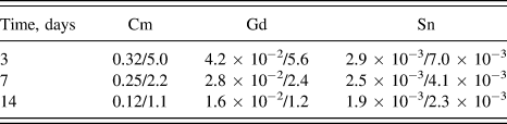
Chemical durability of the Cm-doped specimens was determined using both as-prepared and amorphous specimens. The pellet was hung by a Pt wire in the center of a sealed Teflon container, which was filled with deionized water. The tests were performed at a temperature of 363 K, and samples of the solution were taken on the third, seventh, and 14th days. After each leaching period, the pellet was removed and stored in a sealed tube. Samples of leachate were diluted with concentrated nitric acid (12 M) in amount of 1 vol% and kept at 363 K for 24 h and then chemically analyzed. Then the Teflon container was washed with distilled water, and then the pellet was hung by Pt wire again and a new aliquot of deionized water was used. The specimen surface area to solution volume ratio in the tests was lower (3 m−1) than required by MCC-1 test (10 m−1). Cm concentration in the leachate was determined by alpha-spectrometry. In spite of very high cumulative dose (up to 1.1 × 10¹⁹ α-decays/g or 1.2 dpa) the pellets retained their mechanical integrity, unlike that of actinide-doped monazite and zircon single crystals that experienced spalling and disaggregation due to volume expansion with increasing dose. Reference Burakov48
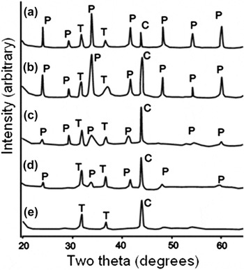
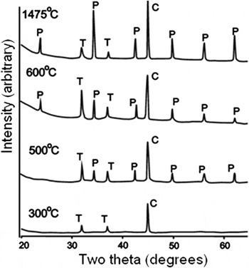
The intensity of the diffraction maxima gradually decreased in the XRD patterns (Fig. 2), and the peak positions shifted to lower angles of two-theta as a result of unit cell expansion over the time of the experiment, i.e., with increasing dose. The unit cell volume expansion varied among the phases studied over a range of 2–6 vol%. The cumulative dose at which XRD diffraction maxima disappear (Fig. 2) was designated to be the critical amorphization dose, D c, at 300 K. Actually, the D c is probably somewhat higher because even after x-ray diffraction maxima disappeared, electron diffraction patterns still confirmed the presence of some small, nanoscale “islands” of crystallinity. The difference in D c, as determined by XRD versus TEM, is approximately 20%. Reference Matzke, van Geel, Merz and Walter49 The fully amorphous specimens were heat-treated in stepwise increments of 100°–200° over a range of 573 and 1750 K and held for 5 h at each temperature stage. The average value between the temperature of the first appearance of diffraction maxima of the phase and the temperature when the peaks were absent was considered to be the critical amorphization temperature, T c (Fig. 3). The actual T c is probably somewhat lower because it is necessary to overcome the activation barrier for the recombination of defects and recovery of the damage domains.
Amorphization of Al-perovskite (P, Nd0.5Sm0.46Cm0.03Pu0.01AlO3) under irradiation with a dose of ×1018 α-decays/g (dpa): (a) 0.01, (b) 0.3 (0.03), (c) 0.8 (0.08), (d) 1.2 (0.12), (e) 2.3 (0.2). T – Teflon, C – diamond (internal standard).

Recovery of the structure of amorphous Al-perovskite (P, Nd0.5Sm0.46Cm0.03Pu0.01AlO3) after heating at different temperatures for 5 h. T – Teflon, C – diamond (internal standard).

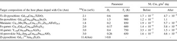
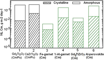
The target compositions of each phase, 244Cm contents, D c and T c values, and leach rates of Cm from the specimens in the 7- to 14-day tests before and after amorphization are compiled in Table III. Details of the experiments and discussion of individual experiments are given in previous studies. Reference Laverov, Velichkin, Omelyanenko, Yudintsev, Petrov and Bychkov11,Reference Laverov, Yudintsev, Livshitz, Stefanovsky, Lukinykh and Ewing14,Reference Yudintsev, Lukinykh, Tomilin, Lizin and Stefanovsky50–Reference Laverov, Yudintsev, Stefanovsky, Omelyanenko and Nikonov53 The radiation-induced amorphization has only a minor effect on leachability. The leach rate of Cm from the amorphous specimens was found to be higher than that from the as-prepared specimens by a factor of three to four, except for Sn-pyrochlore and Al-perovskite, for which the Cm leach rate increased by one order of magnitude. Similar results were obtained for the Cm-doped apatite and pyrochlore, while zirconolite exhibited no appreciable difference in normalized Pu and Cm mass loss (Fig. 4) between the crystalline and amorphous samples. Reference Wald, Weber, Wicks and Ross40 Previous studies have established that the nonradioactive and Pu-doped pyrochlore ceramics (∼12 wt% 238PuO2) exhibited the same dissolution rate in a single-pass flow-through test. Reference Strachan, Scheele, Buck, Icenhower, Kozelisky, Sell, Elovich and Buchmiller26,Reference Icenhower, Strachan, McGrail, Sheele, Rodrigues, Steele and Legore54 But this is not consistent with other experimental results, so these data must be confirmed by replication. Based on their radiation response at 300 K, the phases investigated can be divided into three groups: (i) low resistance (D c ∼ 0.2 dpa) – murataite, perovskite, ferrite garnet; (ii) medium resistance (0.4 ≤ D c ≤ 0.6 dpa) – aluminate garnet, titanate–zirconate pyrochlore; and (iii) high resistance (D c ≥ ∼0.8 dpa) – zirconate and stannate pyrochlores. Critical amorphization temperatures range between 600 and 900 K, which is higher than the range of temperatures anticipated in a mined geologic repository.
Target formulae of the phases, 244Cm content, D c (dpa) and T c values, normalized leach (NL) rate of Cm in water before and after amorphization (7–14 days of testing).

- No data.
Effect of amorphization on actinide leaching by Ref. Reference Mitamura, Matsumoto, Stewart, Tsuboi, Hashimoto, Vance, Hart, Togashi, Kanazawa, Ball and White46 and our data (3–6).
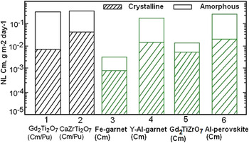
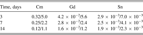
The leach rate of Cm after amorphization increases by a factor of three to ten, depending on the phase. Absolute values of release rate were found to be the lowest for ferrite garnet and murataite, while stannate pyrochlore, aluminate perovskite and garnet were the least durable. Note that the pH of leachate was 4–4.5 due to radiolysis of the water, which markedly affects matrix behavior. Leach rates of long-lived 241Am and 239Pu in distilled water without a radiolytic effect (pH ∼ 6.5) at 363 K from murataite-based ceramics were lower by two to three orders of magnitude than leaching rates from the Cm-doped ceramics. Reference Laverov, Yudintsev, Stefanovsky, Omelyanenko and Nikonov53 These data were obtained in short-time tests; in longer-time tests, leach rates of actinides will be reduced due to incongruent dissolution Reference Lutze and Ewing9–Reference Laverov, Velichkin, Omelyanenko, Yudintsev, Petrov and Bychkov11,Reference Lumpkin, Geisler-Wierwille and Konings19 with formation of a surface film of low-solubility oxides and hydroxides of Ti, Zr, Al, Fe, and Sn (Table IV).
Elemental leach rate (g/m2/d) from Sn-pyrochlore (crystalline/amorphized).
The only phase that did not become amorphous was Gd1.7 241Am0.3Zr2O7. Reference Stefanovsky, Yudintsev and Myasoedov55 The as-prepared sample exhibited major fluorite structure with weak superstructure diffraction maxima due to pyrochlore. At a cumulative dose of 7.9 × 10¹⁷ α-decays/g (0.11 dpa), the XRD pattern showed a broadening of the major peaks at half-height by 20% of the initial value and a reduction of relative intensity. At a dose of 4.6 × 10¹⁸ α-decays/g (0.42 dpa) the a unit cell parameter increased to 5.343 Å (d = 3.085 Å), and unit cell expansion reached a maximum value of ∼1.4 vol%. Finally, at a dose of 5.5 × 10¹⁸ α-decays/g (0.78 dpa) positions of diffraction maxima were shifted to lower 2Θ angles (d 111 reduced to 3.071 Å) and width of the most intense peak was 67% of its value for as compared with the as-prepared specimen. This behavior of the phase is due to two simultaneous processes: formation of the defects and their recombination during recovery. In the early stage of damage accumulation the peaks, in particular (111), have a reduced intensity and broaden because the defect formation rate exceeds the recombination rate. At higher doses, the damage accumulation rate overwhelms the recovery process and the material becomes amorphous. Similar phenomena have been observed in 238Pu-doped zirconia. Reference Burakov, Anderson, Zamoryanskaya, Yagovkina, Nikolaeva, McGrail and Cragnolino56 High radiation resistance is a characteristic of the zirconate pyrochlore. Reference Sykora, Raison and Haire57 Its structure is transformed into a less-ordered fluorite-type structure. Overall, amorphization increases leach rates of actinides from some matrices by several times, but for others – by one and more orders of magnitude (Fig. 4). The phases with the lowest leach rates while still crystalline and which have a minimal change in their solubility after they are fully amorphous are the most attractive actinide host phases, even if they have a low critical dose, D c, at room temperature.
III. ION-IRRADIATED CERAMICS
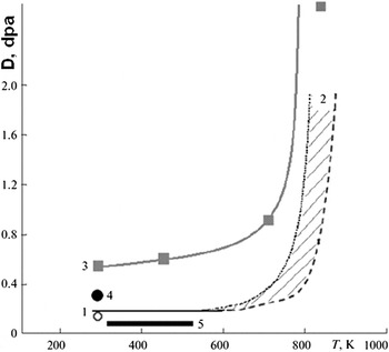
Ion irradiation is one of the most informative and commonly used methods for the study of the radiation response of nuclear waste forms. Major advantages include the short irradiation time (tens of minutes), no induced activation, simultaneous determination of critical amorphization doses of all the phases in the specimen, the possibility to observe radiation damage during irradiation by electron microscopy, and the possibility of investigating a wide variety of structures and compositions. A number of potential waste forms, mainly for Pu, have been investigated by this method. Reference Ewing, Weber, Morss, Edelstein and Fuger17,Reference Ewing, Weber and Lian21,Reference Strachan, Scheele, Buck, Kozelisky, Sell, Elovich and Buchmiller27,Reference Weber, Navrotsky, Stefanovsky, Vance and Vernaz30–Reference Laverov, Yudintsev, Yudintseva, Stefanovsky, Ewing, Lian, Utsonomiya and Wang34,Reference Zhang, Livshits, Lizin, Hu and Ewing51–Reference Laverov, Yudintsev, Stefanovsky, Omelyanenko and Nikonov53,Reference Lumpkin, Smith, Blake, Murphy and Knecht58–Reference Zhang, Lian, Becker, Ewing, Wang, Hu and Saxena64 Major results were obtained for the phases with simple compositions using lanthanides and naturally occurring actinides (U and Th) as surrogates for transuranium elements. One of the reasons for the frequent use of 1 MeV Kr2+ ions is that the critical amorphization doses at room temperature recalculated to dpa are close to those obtained in actinide-doping experiments (Fig. 5). Reference Laverov, Velichkin, Omelyanenko, Yudintsev, Petrov and Bychkov11,Reference Ewing, Weber and Lian21,Reference Wang, Begg, Wang, Ewing, Weber and Kutty31,Reference Zhang, Livshits, Lizin, Hu and Ewing51
Amorphization of synthetic ferrite garnets Reference Livshits, Lizin, Zhang and Ewing52 doped with 244Cm (1) and irradiated with 1 MeV Kr2+ ions (2) and aluminate garnets irradiated with Kr2+ (3) and doped with 244Cm (4), and temperature range in the underground repository (5).

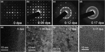
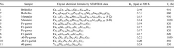
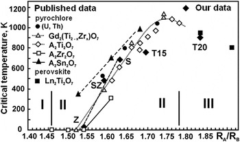
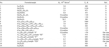
The radiation response of the ceramics based on britholite, pyrochlore, murataite, and garnet under ion-irradiation was investigated, and the D c and T c values were determined (Figs. 5 and 6 and Table V). The samples with waste surrogates were produced by cold pressing and sintering or melting and crystallization by inductive cold crucible melting. Reference Stefanovsky, Yudintsev, Gieré, Lumpkin, Gieré and Stille10 The melted ceramics of britholite and murataite were produced from oxide mixtures in a lab-scale unit with a 65 mm inner diameter copper cold crucible, energized by a 5.28 MHz/10 kW generator. Major attention was focused on the effect of isomorphism in the structure of the phase on its radiation response. The data for murataite, garnet, and britholite have been previously published, Reference Lukinykh, Tomilin, Lizin and Livshits28,Reference Lian, Yudintsev, Stefanovsky, Wang and Ewing33,Reference Laverov, Yudintsev, Yudintseva, Stefanovsky, Ewing, Lian, Utsonomiya and Wang34,Reference Zhang, Livshits, Lizin, Hu and Ewing51–Reference Laverov, Yudintsev, Stefanovsky, Omelyanenko and Nikonov53,Reference Utsunomiya, Wang, Yudintsev and Ewing59–Reference Utsunomiya, Yudintsev and Ewing62 and they are not considered in this study in detail. The radiation response parameters (D c, T c) for the same structure-type vary depending on chemical composition (Table V). We present new data on the ion-irradiation of the phases with A2B2O7 stoichiometry (A is a complex waste surrogate represented by a mixture of rare REE, B = Zr4+, Sn4+, Ti4+). Depending on the element in the B-site, the phases have the pyrochlore (B = Zr4+, Sn4+) or perovskite (B = Ti4+) structure. Pyrochlore is a fluorite derivative structure in which the unit cell of the fluorite structure is doubled. One of eight oxygen ions is absent, reducing the coordination number of the B-site cation from 8 to 6. A2B2O7 compounds form the pyrochlore structure if the A-site to B-site ratio of their ionic radii (R A/R B) is within the range between 1.46 and 1.78 Å. Reference Ewing, Weber and Lian21,Reference Wang, Begg, Wang, Ewing, Weber and Kutty31 At lower R A/R B values, the phases have fluorite-type structure; at higher ratios, the layered monoclinic perovskite-type structure (P21, Z = 4) is stable. The latter is typical of large REE titanates from La to Nd. Light REE cations occupy four different sites with a coordination from 7 to 11, whereas Ti4+ cations are in an octahedral coordination. Reference Whittle, Lumpkin, Blackford, Aughterson, Smith and Zaluzec63,Reference Zhang, Lian, Becker, Ewing, Wang, Hu and Saxena64 Adjacent blocks are shifted along the [100] direction by a half of the TiO6 octahedron. Two REE3+ cations are located within the perovskite-structured layer, and two more cations are located between them. The pyrochlore and perovskite structures are of interest due to their high capacity for REE/An fraction constituents. Waste loading increases from 55 to 65 wt% with the replacement in the B-site of Zr and Sn cations by lighter Ti and transforms the pyrochlore structure into a perovskite-like structure.
Electron diffraction patterns of Ca2.37Th0.56Zr2.03Fe2.96O12 garnet before (a) and after (b–d) irradiation with 1 MeV Kr2+ ions to doses of 0.06 (b), 0.12 (c), and 0.17 (d) dpa and HRTEM images of the initial (e) and irradiated phase to doses 0.06 (f), 0.12 (g), and 0.17 dpa (h). Reference Zhang, Livshits, Lizin, Hu and Ewing51

Radiation response of the phases under 1 MeV Kr2+ irradiation.

Two series of the specimens were prepared by cold pressing and sintering at a temperature of 1773 K for 5 h in air. Zirconate pyrochlore was chosen as a baseline composition. The other members of the series were obtained by complete or partial substitution of Sn or Ti for Zr. Complex mixtures of REE recalculated to 2 atoms of REEs (0.24La + 0.48Ce + 0.20Pr + 0.76Nd + 0.16Sm + 0.10Eu + 0.06Gd – series 1, and 0.24La + 0.46Ce + 0.21Pr + 0.75Nd + 0.15Sm + 0.02Eu + 0.03Gd + 0.14Y – series 2) were used as the REE/An fraction surrogate. Uranium was used as an analog of tetravalent actinides in amount of 0.07 atoms per formula in series 1; Y, which is also a minor component of HLW, was introduced into the specimens of series 2. The specimens were irradiated with Kr ions within the range of 50–1050 K at a fluence rate of 1011 to 1012 ions/(cm2 s). Loss of crystallinity was observed using HRTEM by observing the selected area electron diffraction pattern, which went from having sharp diffraction maxima to the diffuse scattering characteristic of an amorphous material.
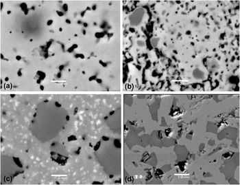
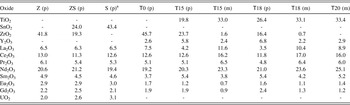
Pyrochlore was the predominant phase in the specimens of series 1 and in the specimen T0 in series 2. Monoclinic titanate dominated in three of the compositions in series 2; two of them (T15 and T18) also contained appreciable amounts of pyrochlore (Fig. 7). In the pyrochlore, variations of compositions at both the A- and B-site were common, while in contrast, the perovskite-type characteristically had REE cations in the A-site, and the B-site was occupied by Ti (Table VI). The other feature of the specimens is close to ideal perovskite stoichiometry and significant deviation from ideal formula for pyrochlore. The latter is demonstrated by absent ocations in the A-site and O2− as compared with their values (2 and 7, respectively) in the ideal formula.
SEM image of the samples Z (a), SZ (b), S (c), and T18 (d). Light – pyrochlore (a–c) or monoclinic titanate (d), dark – ZrO2 (a), SnO2 (b–c) or pyrochlore (d), fine white grains – REE oxide (c), black – pores, scale bar – 2 μm (a–c) or 10 μm (d).

Compositions (wt%, Σ = 100%) of the pyrochlore (p) and monoclinic (m) phases.

– Not introduced.
a Enrichment of REEs is observed, probably capture of REE oxide grains.
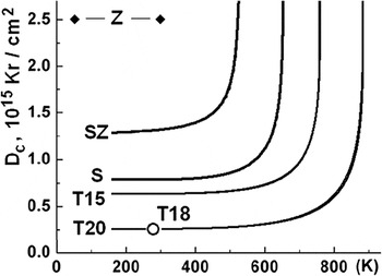
Variations in the radiation response of the different structure-types and compositions have been established. The variations were most significant for the pyrochlore structure: The T c and D c (at 300 K) values decreased as the compositions changed from zirconate–stannate to stannate, and further, with titanate–zirconate. Zirconate pyrochlore did not become amorphous, even at 50 K (Figs. 8 and 9); its structure was transformed into a disordered, defect fluorite-structure. The REE titanate with the perovskite structure had the lowest radiation resistance as is evidenced by D c (∼0.2 dpa at 300 K) and T c (∼910 K) shown in Fig. 8. The results obtained are similar to the data for the phases with simpler compositions, but with the same structure (Table VII). Regardless of the elements in the A-site, zirconate pyrochlore has the highest radiation resistance. Replacement of Zr in the B-site by Sn or Ti reduces radiation resistance, as evidenced by an increase in the critical temperature. Reference Ewing, Weber and Lian21,Reference Wang, Begg, Wang, Ewing, Weber and Kutty31,Reference Ewing66 An increase of the R A/R B ratio leads to an increase in the critical temperature, reaching a maximum value of 1100 K for Gd-titanate pyrochlore. The T c value for the pyrochlore structure, A2Ti2O7 (A = Lu…Gd), increases linearly with the increase of the ratio of the average cationic radius in both the A and B sites. Reference Whittle, Lumpkin, Blackford, Aughterson, Smith and Zaluzec63,Reference Smith, Blackford, Lumpkin, Whitle and Zaluzec67,Reference Lumpkin, Pruneda, Rios, Smith, Trachenko, Whittle and Zaluzec68 These generalities allow for the prediction of the behavior of the phases with different composition but the same structure under irradiation. More precise predictions of the effect of composition on the radiation response can be made by considering the electronic structure, type of bonding (ionic, covalent), and distortion of structure polyhedral. Reference Wang, Begg, Wang, Ewing, Weber and Kutty31,Reference Zhang, Lian, Becker, Ewing, Wang, Hu and Saxena64,Reference Smith, Blackford, Lumpkin, Whitle and Zaluzec67 The monoclinic perovskite structure is typical of LREE from La to Pm and titanate with complex rare earth (REE)/actinide (An) fraction surrogate (specimens in this study: T18 and T20). The behavior of these specimens is similar to that of the simpler Nd2Ti2O7 analog, as well as Gd2(Ti0.75Zr0.25)2O7 pyrochlore. Reference Wang, Begg, Wang, Ewing, Weber and Kutty31,Reference Whittle, Lumpkin, Blackford, Aughterson, Smith and Zaluzec63,Reference Ewing66,Reference Smith, Blackford, Lumpkin, Whitle and Zaluzec67
Temperature dependence of critical amorphization dose of pyrochlore (SZ, S, T15) and perovskite-type phase (T16, T20). The pyrochlore structure of the sample Z is transformed into the less ordered defect fluorite structure at irradiation.

The plot of T c for pyrochlore and perovskite under 1 MeV Kr2+ irradiation against the ionic radii ratio R A/R B from published Reference Lukinykh, Tomilin, Lizin and Livshits28–Reference Weber, Navrotsky, Stefanovsky, Vance and Vernaz30,Reference Mitamura, Matsumoto, Tusboi, Vance, Begg, Hart, Murakami and Ewing47,Reference Burakov48 and our recent data (filled rhombs, samples – Z, SZ, S, T15, T20). I – defect fluorite structure field, II – pyrochlore field, III – perovskite field.

Radiation response of the pyrochlore and perovskite structure actinide host phases under 1 МeV Kr2+ irradiation (D c at 300 K).

1–16 – pyrochlore structure phases, 17–19 – perovskite structure phases. А – REE/An fraction surrogate. Crystalline – remained in a crystalline state (is not amorphized at this temperature).
a Enrichment of REEs is observed, probably due to capture of fine grains of REE oxide.
A feature of ion-irradiation is its very high defect formation rate achieving 10−3 dpa/s, Reference Weber, Ewing, Catlow, Diaz de la Rubia, Hobbs, Kinoshita, Matzke, Motta, Nastasi, Salje, Vance and Zinkle16,Reference Ewing, Weber and Lian21,Reference Ewing66 which is much higher than that experienced in the matrices with 10 wt% 238Pu (10−9 dpa/s) or 239Pu (10−12 dpa/s). At such high dose rates, defects cannot recombine quickly enough and critical temperature, as measured in ion-irradiation experiments, is 100–300 K higher than those measured in actinide-doping experiments. Due to the slower accumulation of defects in the 239Pu-doped phases (T 1/2 = 24,100 years), their critical temperatures are ∼75° lower Reference Ewing, Weber and Lian21 than those for the 238Pu-bearing phases (T 1/2 = 87.1 years). The greater the half-life of an isotope used in an actinide-doping experiment, the greater the difference in critical temperature as measured by actinide-doping versus ion-beam irradiation. The temperature conditions in HLW repository are estimated to be within the range of 300–550 K and depend on external factors (e.g., geothermal gradient) and properties of the waste form (e.g., waste composition and loading). Heat release due to radioactive decay of short-lived actinides causes heating of the matrix for the first several hundred years of storage. Then temperature will decrease to the ambient values because long-lived daughter actinides (237Np, 239Pu, 240Pu) have a much lower heat release (Table I).
For the phases investigated in this study, the critical temperatures increase from 510 to 640 K for Zr/Sn pyrochlore (specimen SZ) and Sn-pyrochlore (specimen S), respectively; to 800 K for Ti/Zr pyrochlore (T15); and 900 K for perovskite (T20). Temperature conditions in underground repository and lower critical temperatures for the actinide-bearing matrices as compared with ion-irradiation suggest that Sn- and Zr/Sn-pyrochlores will not become amorphous, but rather will remain in crystalline throughout the storage period. For Ti/Zr pyrochlore (T15), and for perovskite (T18 and T20), their critical temperatures are too high (750–910 K) for them to remain crystalline during long-term storage in the repository. With a critical dose of 0.3 dpa (monoclinic phase) and 0.6 dpa (pyrochlore in the specimen T15), they will become amorphous due to the decay of radionuclides of the REE/An fraction (95% REE, 5% An) at room temperature (∼300 K) after 20–40 years.
For a waste form containing 40 wt% REE/An fraction, heat release due to actinide decay (241Am – 20% and 244Cm – almost 80%) will only be about 36 kW/m3 (Table I). Taking into account short-lived REEs (144Ce, 147Pm, 152,154,155Eu), the waste form temperature will be somewhat higher. The intensity of heat generation by the waste form and reduction of temperature with time are influenced by (with reduced significance) waste composition and loading, waste package dimensions, interim storage time, density, heat capacity, and thermal conductivity of the waste form and host rock. Based on a preliminary assessment, the 10 cm inner radius cylindrical matrix block at 40 wt% REE/An fraction loading (95% REEs and 5% An: 64% 241Am, 25% 243Am, 10% 244Cm, 1% 245Am) disposed in granite will have a temperature over 400 K for 90 years with a maximum at 450 K in 10 years. This will result in damage recovery and a reduction in the rate of amorphization. Decay and reduction of 244Cm content will decrease heat release in 100–150 years. The disordering rate of the structure will exceed the recovery rate and the material will become amorphous after thousands of years.
IV. CONCLUSIONS
Among the materials investigated in this study, only Zr-pyrochlore and, under some circumstances, the stannate/zirconate and stannate pyrochlores, will remain crystalline throughout the period of geologic disposal, i.e., for hundreds of thousands of years. The REE-titanate perovskite and the titanate/zirconate pyrochlore will become amorphous in less than a thousand years, even considering the high heat release rate by the actinide fraction. Major criteria for the selection of the waste form for the actinide fraction are: high waste loading, low solubility in underground waters (for both the crystalline and amorphous state), as well as the feasibility of full-scale production. The radiation response of actinide-doped materials is of lesser importance. Most of the phases that have been proposed for Pu immobilization are not highly resistant to radiation, and they will become amorphous in less than a thousand years. However, there is generally no significant change in actinide release from these fully damaged materials. Reference Laverov, Velichkin, Omelyanenko, Yudintsev, Petrov and Bychkov11,Reference Laverov, Yudintsev, Livshitz, Stefanovsky, Lukinykh and Ewing14,Reference Lukinykh, Tomilin, Lizin and Livshits28,Reference Yudintsev, Lukinykh, Tomilin, Lizin and Stefanovsky50,Reference Laverov, Yudintsev, Stefanovsky, Omelyanenko and Nikonov53 From this point of view, and taking into consideration a high content of the waste and possibility for industrial scale production, the perovskite structure titanates are of significant interest. The radiation-resistant zirconate pyrochlore requires a long sintering time due to a very low phase formation reaction rate and has a high melting point, thus hindering synthesis.
ACKNOWLEDGMENTS
The work was performed under the support of the Russian Foundation for Basic Research (Projects #13-05-00085 and #14-05-31034).
RCE's effort and the ion-beam irradiation experiments were supported by the U.S. Department of Energy Office of Science, Office of Basic Energy Sciences Energy Frontier Research Centers program under Award Number DE-SC0001089.
The authors thank L.A. Kochetkova, M.S. Nikolsky, B.S. Nikonov for their help in examination of the specimens and V.I. Malkovsky for temperature calculations.
The electron microscopy with in situ ion irradiation was accomplished at Argonne National Laboratory at the IVEM-Tandem Facility, a U.S. Department of Energy Facility funded by the DOE Office of Nuclear Energy, operated under Contract No. DE-AC02-06CH11357 by the University of Chicago Argonne, LLC. L.M. Wang, S. Utsunomiya, J. Lian, J. Zhang, and W. Li thank the staff and scientists at HVEM- and IVEM-Tandem Facility at Argonne National Laboratory for their help and support during the ion irradiation experiments. This facility was essential for the completion of the studies summarized in this paper.