Introduction
High-strength antagonistic behavior of lightweight periodic complex structures has led to increasing interest in various applications such as aerospace industry,[ Reference Valdevit, Jacobsen, Greer and Carter 1 ] biomedical,[ Reference Wang, Zhao, Chang, Qian, Zhang, Wang, Vannan and Wang 2 , Reference Murr, Gaytan, Medina, Lopez, Martinez, Machado, Hernandez, Martinez, Lopez, Wicker and Bracke 3 ] devices,[ Reference Zhu, Liu, Qian, Han, Duoss, Kuntz, Spadaccini, Worsley and Li 4 , Reference Xu, Gallant, Wunderlich, Lohmann and Greer 5 ] and photonics.[ Reference Von Freymann, Ledermann, Thiel, Staude, Essig, Busch and Wegener 6 ] The mechanical properties of these periodic structures such as modulus and strength are usually governed by the volume fraction of the constituent material. For three-dimensional (3D) architecture materials, the truss design and the nodal connectivity (or coordination number) of the truss structure have a distinct influence on their mechanical properties.[ Reference Christensen, Kadic, Wegener, Kraft and Wegener 7 ] For the low-density materials such as aerogels and foams that are below 10 mg/cm3 with random cellular architectures generally results in specific properties (e.g., stiffness, strength, energy absorption, and conductivity), which are far below those of the bulk material.[ Reference Gibson and Ashby 8 ] It was reported that by controlling both dimensions and periodicity of the architecture, microlattice follows E/E s∞(ρ/ρ s)2 relation, where E is the measured compressive Young's modulus and ρ is the density of the structure. This relation is an important measure of the dependency of the mechanical property in terms of Young's modulus on each complex structure types.[ Reference Schaedler, Jacobsen, Torrents, Sorensen, Lian, Greer, Valdevit and Carter 9 ]
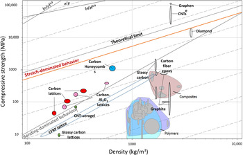
Depending on their geometry and nodal connectivity, these architected systems with different unit-cell structures can be deformed by either bending-dominated mechanism or stretch-dominated mechanism,[ Reference Ashby, Scheffler and Colombo 10 ] which varies in their failure mechanism.[ Reference Montemayor and Greer 11 ] The latter is of particular interest because these structures lead to the highest strengths even in the relative density range of less than 0.1%, as compared with bending-dominated structures such as natural foams.[ Reference Bauer, Schroer, Schwaiger and Kraft 12 – Reference Dong, Deshpande and Wadley 14 ] Nodal connectivity (Z) is the number of struts that meet at each node of the microstructure. The failure response of a structure by bending-dominated or stretch-dominated mechanism can be governed by its nodal connectivity. A 3D structure must have a connectivity of M = 6 at the nodes to be rigid and a connectivity of M = 12 to be stretch-dominated; structures with 6 < M < 12 are bending-dominated.[ Reference Fleck, Deshpande and Ashby 15 , Reference Deshpande, Ashby and Fleck 16 ] The condition for stretch-dominating behavior is further defined by the Maxwell's stability criterion which, for a 3D structure, is given by M = b − 3j + 6 = 0 ≥ 0, where b and j are the number of struts and nodes in the unit cell. This is discussed later in this section. By fabricating 3D periodic lattices comprised stretching-dominated structures such as the octet or the octahedral unit cells, 3D structural metamaterials can be generated with near-linear modulus and strength to density ratio that is ultralight as well as having excellent reversibility of the induced deformation.[ Reference Meza, Zelhofer, Clarke, Mateos, Kochmann and Greer 17 ] To fully explore the potential of these ultralight architected systems, both the design of the material composition and the corresponding advanced fabrication techniques must be developed in addition to controlling the architecture. It has been exhibited in the recent advances that by controlling the composition and the architecture of the material, the mechanical properties such as the Young's modulus and the strength can significantly be improved.[ Reference Fleck, Deshpande and Ashby 15 , Reference Valdevit, Bauer and Baldacchini 18 – Reference Zhu, Li, Ogata and Yip 20 ] Bauer et al. has demonstrated the fabrication of smallest nano-honeycomb structures by carbonization, which exhibited compressive strengths of up to 1.2 GPa at 0.6 g/cm3; the strength is exceptionally high in comparison with the carbon and polymer microlattice structure for a given density, as can be seen in the Ashby diagram in Fig. 1. Paste or viscoelastic ink extrusion have also been demonstrated to make architected materials with improved strength by incorporating highly anisotropic silicon carbide whiskers and carbon fibers as fillers to reinforce the epoxy resin, and the honeycomb structures synthesized with fiber reinforcement showed higher tensile strength and 10–20 times higher longitudinal Young's modulus than that of the most commercial 3D-printed polymers.[ Reference Compton and Lewis 21 ]
Ashby graph on compressive strength–density. This chart compares different architected materials reported so far, as well as bulk materials. This graph is designed using the Software CES Edupack 2014 (Granta Design).

To fabricate these complex structures with diverse materials in a small length-scale, 3D printing is regarded as the most promising technique.[ Reference Zheng, Lee, Weisgraber, Shusteff, DeOtte, Duoss, Kuntz, Biener, Ge, a Jackson, Kucheyev, Fang and Spadaccini 22 ] It is an additive manufacturing method that enables fabrication of complex 3D architectures based on computer-designed models.[ Reference Farahani, Chizari and Therriault 23 ] Additive manufacturing (AM) offers new possibilities to realize complex cellular architectures, including octet truss lattices, earlier limited by the fabrication methods. With the technological advances in fabrication methods, 3D lattices with high structural complexity and small feature sizes can be fabricated by various 3D-printing methods[ Reference Montemayor, Chernow and Greer 24 ] such as micro-stereolithography,[ Reference Zheng, Lee, Weisgraber, Shusteff, DeOtte, Duoss, Kuntz, Biener, Ge, a Jackson, Kucheyev, Fang and Spadaccini 22 ] direct laser writing (DLW),[ Reference Bauer, Schroer, Schwaiger and Kraft 12 , Reference Bückmann, Stenger, Kadic, Kaschke, Frölich, Kennerknecht, Eberl, Thiel and Wegener 25 , Reference Brenne, Niendorf and Maier 26 ] two-photon lithography (TPL),[ Reference Montemayor, Meza and Greer 27 , Reference Meza, Das and Greer 28 ] fused deposition modeling,[ Reference Naghieh, Karamooz Ravari, Badrossamay, Foroozmehr and Kadkhodaei 29 ] ultraviolet (UV)-assisted 3D printings,[ Reference Farahani, Lebel and Therriault 30 ] etc., each of which offers controlled composition, geometric shape, function, and complexity over traditional manufacturing methods.[ Reference Compton and Lewis 21 ] In particular, 3D architected systems combined with reinforced composite materials have been recognized as a promising approach to fabricate mechanically strengthened lightweight structures.
In this prospective article, we discuss the recent trends in the study of architected structures using 3D-printing techniques. Firstly, the mechanical properties of the architected materials will be discussed, followed by the different methods of 3D printing with functional materials, and finally, the future prospect and its potential applications is discussed.
Mechanical property of 3D cellular composite
Three factors that influence the properties of cellular structures are:
-
(i) the properties of the solid bulk material;
-
(ii) the topology (connectivity) and shape of the cell edges and faces; and
-
(iii) the relative density,
 $\tilde \rho /\rho _{\rm s} $
, where
$\tilde \rho $
is the density of the cellular structure and ρ
s that of the solid of which it is made.[
Reference Ashby
31
]


By changing the cellular architecture, desirable mechanical properties can be achieved. According to the report by Ashby, the strength and modulus of the architecture material scales with the relative density as can be seen from (Fig. 1).[
Reference Gibson and Ashby
8
] The conventional cellular material such as the foam exhibits poor scaling, where the slope of the strength versus
 $\tilde \rho /\rho _{\rm s} \; $
is 2, due to its bending-dominated behavior. However, stretch-dominated structure such as the octet is close to the ideal scaling behavior in which the slope of the strength versus
 $\tilde \rho /\rho _{\rm s} $
is 1. The deformation mechanisms of architected materials (bending- or stretch-dominated) decide their mechanical properties, and the suitable ordered lattice architecture can be chosen to design metamaterial with desired mechanical properties. After the elastic limit is reached in stretch-dominated structure, failure can occur by a number of possible mechanisms, where the individual struts can plastically deform, or buckle or fracture. Thinner struts with small t/L ratio, where t is the thickness of the shell and L is the length of the individual strut, would tend to cause buckling, while thicker struts will result in plastic deformation to result in more load-bearing capability. The different possible collapse mechanisms compete upon deformation, and the one that requires the lowest stress dominates.
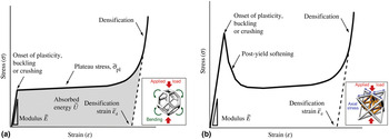
In Fig. 2(a), the stress–strain curve initially exhibits linear elastic region up to its elastic limit, at which point the struts of the cell yield, buckle or fracture. The structure continues to deform at a nearly constant stress (the “plateau stress”
 $\tilde \sigma _{{\rm pl}} $
), which corresponds to plastic, non-recoverable deformation of the truss until the structure starts to collapse where the opposite sides of the cells impinge (the “densification strain”
 $\tilde \in _{\rm d} $
). As densification occurs due to collapse of the structure, the stress rises steeply [cells in the insets of Fig. 2(a) and (b)]. In Fig. 2(b), the stretch-dominated structure shows similar linear elastic region up to the elastic limit, but there is drop in flow stress after the yield point. The yield point is attained as strut failure is first observed, and then decreased rapidly with increasing strain due to plastic buckling or brittle collapse of the struts. Later, the curve follows a plateau and finally rapid hardening due to the densification effect as the deformed struts come in contact with each other. This occurs because the mechanisms of deformation transitions from buckling, which occurs at lower stresses after the yield point, to plastic deformation of the material after the material densifies. Typically, the modulus and the initial strength of the stretch-dominated structure are significantly larger than those of the bending-dominated structure of the same relative density. Most foams are bending-dominated and their stiffness and strength (at a given relative density) is far below the levels of stretch-dominated structures such as the honeycomb or octet.
Strain–strain behavior of: (a) bending-dominated lattice and (b) stretching-dominated lattice.[ Reference Zheng, Lee, Weisgraber, Shusteff, DeOtte, Duoss, Kuntz, Biener, Ge, a Jackson, Kucheyev, Fang and Spadaccini 22 , Reference Ashby 31 ]

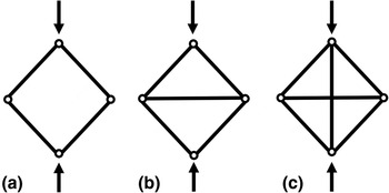
For designing a cellular structure, the layout of its struts is important, which decides the dominated failure mechanism in that particular structure. According to the Maxwell criterion, defined previously, if M < 0, the frame has one or more degrees of freedom as shown in Fig. 3(a) that allows for displacements and thus does not contribute to stiffness or strength of the structure. If the joints are locked, the struts of the frame bend when the structure is loaded. When a structure with low-connectivity is loaded, the struts buckle results in a low modulus. The deformation is predominantly bending-dominated because the thin shell buckles easily. If, instead, M = 0, the frame structure is no longer subject to buckling and the individual struts carry tension or compression upon loading as shown in Fig. 3(b), and it becomes a stretch-dominated structure. Stretch-dominated structures have higher structural efficiency than bending-dominated due to the extra support from the stretching struts. For structures with M > 0, the condition of self-stress arises as a result of the horizontal bar being shortened that consequently puts the vertical struts in tension even without the application of external loads as shown in Fig. 3(c).[ Reference Ashby 31 ] Additionally, mechanical properties of 3D truss structures are known to be sensitive to defects such as misplaced joints and node positions, and this sensitivity is highly dependent on their nodal connectivity. Lattices with a high connectivity of six or more, such as the triangular lattice, are less sensitive to defects, compared with square lattices. For structures whose connectivity value is in a transitional range, like a square lattice, it deforms by stretching when loaded uniformly, but upon the introduction of a defect such as a macroscopic crack, the struts deform by a combination of stretching and bending mechanisms. This failure behavior can vary depending on the degree of imperfection.[ Reference Schaedler, Jacobsen, Torrents, Sorensen, Lian, Greer, Valdevit and Carter 9 ]
The pin-jointed frame in three forms: (a) structure folds up when loaded and if its joints are welded together, the struts bend, becoming a bending-dominated structure. The triangulated frame at (b) is stiff when loaded because the transverse strut carries tension and is a stretch-dominated structure. The frame at (c) is overconstrained; if the horizontal bar is shortened the vertical one is comes in tension even when no external loads are applied, a state of self-stress.[ Reference Ashby 31 ]

The modulus of the cellular structure is given as
 $\tilde E/E_{\rm s} = (\tilde \rho /\rho _{\rm s} )^2 $
for bending-dominated behavior, and the failure strength
 $\tilde \sigma _{{\rm pl}} $
is given as
 $\tilde \sigma _{{\rm pl}} /\sigma _{y,{\rm s}} = (\tilde \rho /\rho _{\rm s} )^{3/2} $
; whereas for the stretch-dominated structure, both show linear behavior as
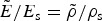 $\tilde E/E_{\rm s} = \tilde \rho /\rho _{\rm s} $
, and
 $\tilde \sigma _{{\rm pl}} /\sigma _{y,{\rm s}} = \tilde \rho /\rho _{\rm s} $
, where
 $\tilde \rho $
is the density of the foam, ρ
s is the density of the solid, and E
s is the modulus of the solid of which the strut is made. These relations are important when comparing 3D cellular structures with alternative topologies for their modulus and strengths with respect to the relative density to evaluate their mechanical properties. As stated earlier, the modulus and initial yield strength of a stretching-dominated cellular solid are typically much greater than those of a bending-dominated cellular material of the same relative density. This makes stretch-dominated cellular solids attractive alternatives to bending-dominated foamed materials for lightweight structural applications.[
Reference Deshpande, Ashby and Fleck
16
] One of the most common cellular structures is honeycomb, which is highly anisotropic in stiffness. Regular hexagon honeycombs, when loaded parallel to the axis of hexagons, in which the cell walls are aligned with the load, expand or compress rather than undergoing bending and lie near the ideal-stretch line of the E versus ρ graph, while when loaded normal to this direction, the inclined edges of the hexagon collapse due to bending.[
Reference Ashby
31
] The stretching dominant behavior is further maximized by making the honeycombs fully triangulated.[
Reference Compton and Lewis
21
,
Reference Bauer, Hengsbachb, Tesaria, Schwaigera and Kraft
32
]
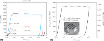
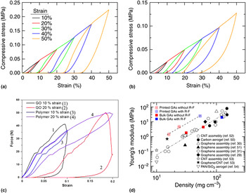
Figures 4 and 5 show the enhanced stress–strain behavior of carbon triangular honeycombs and graphene-based materials[
Reference Zhu, Han, Duoss, Golobic, Kuntz, Spadaccini and Worsley
33
,
Reference Lin, Jin, Zhang, Wang, Wang, Zhou and Cheng
34
] respectively, which is observed by performing their compression tests.
(a) Stress–strain curves showing that strength and stiffness increase with decreasing dimensions and (b) measured stress–strain curve for a carbon honeycomb with triangular unit cells with an edge length of 970 nm.[ Reference Bauer, Schroer, Schwaiger and Kraft 12 ]

Compressive properties of graphene-based architecture materials. Stress–strain curves during loading–unloading cycles in sequence of increasing strain amplitude for: (a) bulk graphene aerogel (123 mg/cm3); (b) 3D printed graphene aerogel microlattice (53 mg/cm3) using the GO ink with (R–F) solution[ Reference Zhu, Han, Duoss, Golobic, Kuntz, Spadaccini and Worsley 33 ]; (c) compression test of 3D-printed polymer and GO-reinforced parts[ Reference Lin, Jin, Zhang, Wang, Wang, Zhou and Cheng 34 ]; and (d) the relationships between Young's modulus and density of bulk and printed graphene aerogels.[ Reference Zhu, Han, Duoss, Golobic, Kuntz, Spadaccini and Worsley 33 ]

Nanofabrication for 3D cellular composites
Fabrication of architected structures requires a sophisticated patterning approach; the 3D printing, for example, uses computer-aided designs and prints layer-by-layer.[ Reference Raney and Lewis 35 , Reference Serra, Planell and Navarro 36 ] Different approaches have been explored so far to print 3D architectures, and these vary from using ink and filament-based methods such as fused deposition modeling (FDM) and polyjet technology to light-based methods involving DLW, and micro-stereolithography to create sub-micrometer scale structures. Mostly polymer structures are used as a template and then are turned into carbon structures after post-annealing processing.[ Reference Szczurek, Ortona, Ferrari, Rezaei, Medjahdi, Fierro, Bychanok, Kuzhir and Celzard 37 ]
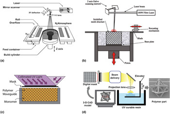
Light-induced fabrication techniques work on the generation of 3D structures by solidifying the light-sensitive polymer areas where the light is exposed. 3D architectures are fabricated by using photopolymerizable resins in stereolithography or digital projection lithography, while polymer powders are merged together in selective laser or e-beam melting (Fig. 6).[ Reference Xiong, Mines, Ghosh, Vaziri, Ma, Ohrndorf, Christ and Wu 38 , Reference Kruth, Mercelis, Van Vaerenbergh, Froyen, Rombouts, Van Vaerenbergh, Froyen, Rombouts, Van Vaerenbergh, Froyen and Rombouts 39 ] These printing methods have recently been used widely as they are capable of generating complex 3D structures at resolutions comparable with those achieved by ink-based printing techniques and with smaller feature sizes in the range of 5–500 nm.[ Reference Raney and Lewis 35 ] Jacobsen et al. have introduced yet another method involving the polymer waveguide technology, where a self-propagating polymer waveguide is formed from a single-point exposure of light, which yielded a high-aspect-ratio polymer fiber (length/diameter > 100) in a few seconds.[ Reference Jacobsen, Barvosa-Carter and Nutt 40 ] Upon exposure of light in the UV range, polymerization of the photopolymer begins at the point of exposure and the subsequent incident light is trapped in the polymer because of internal reflection, producing an interconnected 3D lattice. The architecture can be easily altered by changing the angle of the incident light, diameter, of the individual waveguides and the aperture spacing on the mask. A wide array of different architectures with unit-cell dimensions ranging from 0.1 to >10 mm can be made by altering the mask pattern and the angle of the incident light.[ Reference Schaedler, Jacobsen, Torrents, Sorensen, Lian, Greer, Valdevit and Carter 9 , Reference Torrents, Schaedler, Jacobsen, Carter and Valdevit 41 ] Micro-stereolithography method has been extensively used to fabricate 3D lattices with high structural complexity and with feature sizes ranging from tens of micrometers to centimeters.[ Reference Zheng, Lee, Weisgraber, Shusteff, DeOtte, Duoss, Kuntz, Biener, Ge, a Jackson, Kucheyev, Fang and Spadaccini 22 , Reference Lausic, Bird, Steeves and Hibbard 42 ] Each image is projected through a reduction lens onto the surface of the photosensitive resin, curing the exposed liquid. However, this method has limitation in their scaling and material diversity. Similar technique is the TPL in which structures are written using laser powers of range 6–14 mW and a writing speed of ~50 µm/s approximately. The laser power is used to control the diameter of the struts, and the speed to control the quality of the structures.[ Reference Meza, Das and Greer 28 ] TPL combines the advantages of 3D printing and photolithography to provide full control in creating small-scale structures on a variety of length scales with a resolution down to 150 nm scale.[ Reference Bauer, Schroer, Schwaiger and Kraft 12 , Reference Meza, Zelhofer, Clarke, Mateos, Kochmann and Greer 17 , Reference Bückmann, Stenger, Kadic, Kaschke, Frölich, Kennerknecht, Eberl, Thiel and Wegener 25 , Reference Montemayor, Meza and Greer 27 , Reference Bauer, Schroer, Schwaiger, Tesari, Lange, Valdevit and Kraft 43 ] Lauren C. Montemayor, in their work,[ Reference Montemayor, Meza and Greer 27 ] showed the fabrication of hollow metallic nanolattices with dimensions spanning from 100 to 1 mm and larger. Another similar technique is DLW, which allows for production of almost arbitrary polymeric geometries using laser inscription.[ Reference Bauer, Hengsbachb, Tesaria, Schwaigera and Kraft 32 ] Laser light is coupled into an inverted microscope and focused onto the negative-tone photoresist SU-8.[ Reference Von Freymann, Ledermann, Thiel, Staude, Essig, Busch and Wegener 6 ] In recent works, hollow lightweight structures are also studied, which are made by removing the polymer from the coated nanolattices using focused ion beam milling or etching. These are focused on to create structures with lower density.[ Reference Montemayor, Meza and Greer 27 , Reference Meza, Das and Greer 28 ]
Light-induced fabrication methods: (a) A typical SLS layout, inset is the image of lightweight sandwich panel made from glass-filled nylon[ Reference Kruth, Mercelis, Van Vaerenbergh, Froyen, Rombouts, Van Vaerenbergh, Froyen, Rombouts, Van Vaerenbergh, Froyen and Rombouts 39 ]; (b) Schematic representation of the SLM process with selectively melted fine metal powders to form ultralight metallic microlattice[ Reference Xiong, Mines, Ghosh, Vaziri, Ma, Ohrndorf, Christ and Wu 38 ]; (c) Open-cellular microtruss structures formed from a 3D pattern of interconnected self-propagating polymer waveguides[ Reference Torrents, Schaedler, Jacobsen, Carter and Valdevit 41 ]; and (d) Projection micro-stereolithography, a layer-by-layer fabricated octet-truss microstructures with resolution of ~5 µm.[ Reference Zheng, Lee, Weisgraber, Shusteff, DeOtte, Duoss, Kuntz, Biener, Ge, a Jackson, Kucheyev, Fang and Spadaccini 22 ]

Selective laser sintering (SLS) or selective laser melting (SLM) is a technique in which the surface of metal powder is selectively melted by laser, and then a new layer of powder is deposited, thus building up the component,[ Reference Xiong, Mines, Ghosh, Vaziri, Ma, Ohrndorf, Christ and Wu 38 ] and has also been extensively used to grow decent quality grapheme.[ Reference Yang, Yan, Liu, Chabi, Xia and Zhu 44 ] SLM enables printing of metals, and functions through focused laser melting of metal powder in a layer-by-layer synthesis with structures of up to centimeter dimensions. Although among the different rapid prototyping (RP) techniques, SLS has the advantage of being able to process a wide range of materials. However, it holds drawbacks in creating large dimensions (millimeter range) of the smallest features achievable and forming rough metal surfaces. They are usually applied in production of orthopedic and dental implants.[ Reference Taneva, Kusnoto, Evans and Bourzgui 45 ]
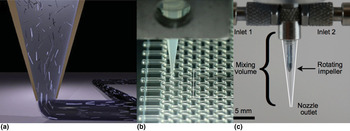
Ink or filament extrusion-based fabrication methods involve printing directly with the form of ink or solid filament, extruding through a nozzle and forming the desired pattern without the use of light or lasers (Fig. 7). Direct ink writing helps in designing of concentrated viscoelastic inks that exhibit significant shear thinning to allow extrusion through micronozzles under ambient conditions at normal pressures.[ Reference Compton and Lewis 21 ] By carefully tailoring the ink composition and rheology, the printability, architecture, and properties of patterned 3D structures can be controlled. The primary challenge for this method is to design viscoelastic ink materials possessing thixotropic behavior to facilitate flow under pressure and a rapid dilatant recovery after deposition resulting in shape retention.[ Reference Compton and Lewis 21 ] Clausen et al. successfully demonstrated the fabrication of 3D printing with elastomeric ink. Ink deposition is performed using a 200 µm syringe with a structure consisting of ten layers with 136 µm layer thickness.[ Reference Clausen, Wang, Jensen, Sigmund and Lewis 46 ] In another experiment, a typical graphene oxide (GO) ink consisting of mixing 6 g of 40 mg/ml GO suspension, 0.343 g (NH4)2CO3 solution and 0.7 g fumed silica, is extruded through a micronozzle to pattern 3D structures. To prevent the ink from drying and clogging of the tip, the printing is carried out in an organic solvent bath (isooctane) that is not miscible with the aqueous ink.[ Reference Yang, Chabi, Xia and Zhu 47 ] The 3D fountain pen growth has so far been demonstrated with metallic, polymer,[ Reference Kim, Seol, Pyo, Lee, Je and Margaritondo 48 ] and carbon nanomaterial wires.[ Reference Seol, Chang, Kim and Jung 49 , Reference Kim, Chang, Kim, Yang, Han, Lee, Kim and Seol 50 ] A meniscus of the monomer solution is created outside the micropipette opening and as the micropipette is pulled away, the meniscus is stretched and its cross-section decreases. When its size reaches the nanoscale, the monomer meniscus is rapidly polymerized by O2 in air, forming a polymer nanostructure with a high-aspect ratio by continuous pulling. This technique has been demonstrated to successfully fabricate nanowires of conducting polymers such as polypyrrole (PPy) and poly(3,4-ethylenedioxythiophene): poly(styrene sulfonate) (PEDOT:PSS); a composite of 0.07–0.62 wt.% multi walled carbon nanotubes (MWNTs) in PEDOT:PSS and reduced GO by using a colloidal dispersion of GO sheets, and reducing it by thermal or chemical treatment (with hydrazine).[ Reference Kim, Seol, Pyo, Lee, Je and Margaritondo 48 ] These nanowires can be used in applications such as stretchable interconnects and 3D transducers in gas sensors. The FDM is the technique, which builds parts layer-by-layer from the bottom up by heating and extruding thermoplastic filament. It is a very simple method which does not require solvent or post processing, and has a flexibility in material selection.[ Reference Karamooz Ravari, Kadkhodaei, Badrossamay and Rezaei 51 ] However, it still suffers from the difficulty of downsizing printed structures to the nanometer scale, which is required to fabricate ultralight-architected materials[ Reference Kim, Chang, Kim, Yang, Han, Lee, Kim and Seol 50 ] Polyjet technology is another widely used technique, which works similar to inkjet printing, but instead of jetting drops of ink onto paper, these 3D printers jet layers of curable liquid photopolymer onto a build tray and are instantly cured by UV-light. It also allows for mix-printing of any two materials to deliver the desirable mechanical properties in a composite form.[ Reference Ober, Foresti and Lewis 52 ] The 3D printing using polyjet technology is performed with the maximum resolutions of 16 µm in vertical and 42 µm in in-plane directions.[ Reference Wang, Chang, Chen, Zhang and Wang 53 ] In addition, 3D printing of high-strength materials can largely benefit along with recent progress in manufacturing techniques that will lead to demonstration of ultra-light weight complex architectures with remarkable strength. At scales <100 µm, the mechanical properties of the base material are the same as in the bulk. Therefore, to obtain enhanced mechanical properties, which strongly depend on the microarchitecture of the material, it is essential to choose a suitable fabrication technique.
The ink-based extrusion fabrication technique: (a) Schematic representation of composite ink deposition[ Reference Compton and Lewis 21 ]; (b) Optical image of the fabrication of PDMS-based architectures using direct ink writing[ Reference Clausen, Wang, Jensen, Sigmund and Lewis 46 ]; and (c) Optical image of the impeller-based active mixer for 3D printing of homogenously mixed inks.[ Reference Ober, Foresti and Lewis 52 ]

Nanomaterials for 3D cellular composites
In the recent investigation on 3D-printed structures, a polymer structure is fabricated which is either used as a sacrificial template that is then etched away after being coated with an alternative materials, or further processed to generate ceramics or carbon, etc. Inspired from the biologic materials such as bone, enamel or nacre, 3D structures were also fabricated by using ceramic building blocks of 1–100 nm size.[ Reference Bauer, Schroer, Schwaiger, Tesari, Lange, Valdevit and Kraft 43 ] At small dimensions, the fracture toughness is reported to be increased since the flaw or crack size decreases with the feature size that makes crack propagation more difficult and also as the secondary compliant phase can deflect crack propagations. Thus, the fracture strength increases with decreasing size, and has been predicted to reach theoretical strength at a critical thickness.[ Reference Gao, Ji, Jäger, Arzt and Fratzl 54 ] Apart from morphology and density, the functional properties of architected materials are mostly governed by the material composition.[ Reference Zhu, Han, Duoss, Golobic, Kuntz, Spadaccini and Worsley 33 ] Below we discuss how the 3D-printed materials ranging from polymer to carbon and their composites to create architected structures with high strength.
Polymer: As seen in most of the methods in the previous section, polymer is the main source material. Using stereo lithography process with 34 µm horizontal and 29 µm vertical accuracy of the printer, architected structures are fabricated with density of 1.189–0.004 g/cm3. The hardened structures have mechanical properties with Young's modulus of 1900–100 MPa, and a compressive yield strength of 42.2–1.5 MPa.[ Reference Lausic, Bird, Steeves and Hibbard 42 ] In another experiment, polylactic acid (PLA) is combined with a bioactive CaP glass to fabricate 3D biodegradable scaffolds with considerably higher mechanical properties than other polymer scaffolds.[ Reference Serra, Planell and Navarro 36 ]
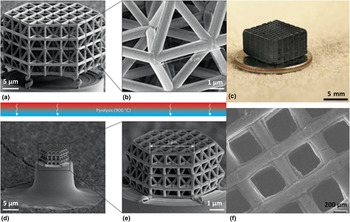
Carbon: Carbon nanomaterials have superior mechanical properties than polymer materials and 3D cellular structures of these materials can further promote stronger mechanical strengths with higher specific surface areas.[ Reference Ma and Chen 55 ] However, it is a challenge to fabricate 3D carbon structures in a defined architecture, and therefore there is a need to discover different methods. One common method to form carbon structures is 3D printing a stabilized polymer structure as a template and subsequently being converted into carbon through a pyrolysis step. This approach is 3D-printing process and is not applicable for printing carbon alone, as pure carbon can neither be molten, cross-linked nor polymerized after its layer-by-layer deposition.[ Reference Szczurek, Ortona, Ferrari, Rezaei, Medjahdi, Fierro, Bychanok, Kuzhir and Celzard 37 ]. Consequently, different carbon sources are surveyed to fabricate carbon structures, such as grapheme,[ Reference Yang, Chabi, Xia and Zhu 47 ] carbon fiber epoxy, carbon composites, etc. as can be seen in Fig. 8, which demonstrates architectural carbon structures with low relative density created by adopting different methodologies. Pyrolysis at 1000–3000°C transforms the printed cellular structures from polymer into considerably smaller carbon structures with significantly enhanced physical properties with shrinkage of structure up to 90%. Carbon nanostructure with single struts shorter than 1 µm and strut diameters of 200 nm are fabricated which show remarkable mechanical properties in the form of the tetrahedral lattice or the honeycombs structures with triangular unit cells of edge length 5–10 µm.[ Reference Bauer, Schroer, Schwaiger and Kraft 12 ]. Atomic bonds after pyrolysis are confirmed as predominantly pure carbon-to-carbon structures. Furthermore, 3D graphene structures are the most commonly investigated carbon-architected materials for its unique characteristics of low density and high mechanical strength with particular highlight on graphene aerogels, which form an ultra-low density structures with excellent structural integrity and microarchitecture accuracy. Their production involves sol–gel chemistry, which involves reducing GO to form a highly cross-linked graphene hydrogel, followed by freeze-drying or supercritical drying to remove the absorbed water.[ Reference Ma and Chen 55 ] Typically, the 2D GO/graphene sheets are assembled to form 3D graphene networks by dispersing GO in a solution and adding cross-linkers or ultrasonicating the GO dispersion solution to cause gelation. This is then followed by reduction processes, and special drying techniques to obtain graphene structures.[ Reference Zhu, Han, Duoss, Golobic, Kuntz, Spadaccini and Worsley 33 ]
Architectured structures from carbon and composite materials: (a) Polymer structure before pyrolysis: whole structure; (b) close-up view of a single unit cell[ Reference Bauer, Schroer, Schwaiger and Kraft 12 ]; (c) a 3D printed graphene aerogel microlattice; (d, e) pyrolysis of polymer nanolattices, which shrinks isotropically to about 20% of their initial size, from (a) and (b), respectively, to generate glassy carbon; and (f) Scanning electron microscope (SEM) image of the same graphene aerogel.[ Reference Yang, Chabi, Xia and Zhu 47 ]

Nano-composite materials: Due to the weak mechanical property of the polymer and its resulting poor surface quality of the parts, the progress in additive manufacturing technology has been greatly hindered in its materials versatility. Therefore, reinforcing polymers with fillers to increase their mechanical properties is extensively investigated. The design and behavior of polymer nanocomposites mainly depend on the aspect ratio of nanofillers, percolation threshold and interfacial property of nanofiller and matrix, where the dispersion of nanofillers is a critical parameter that determines the properties of polymer nanocomposites. Due to its high mechanical strength, graphene oxide has been used as filler to strengthen polymers. Lin et al. demonstrates the composite formation by dispersed SLGO with added polymer resin.[ Reference Lin, Jin, Zhang, Wang, Wang, Zhou and Cheng 34 ] Other carbon-based structure that have been broadly under study involves carbon fiber composites (CFRP), which have a high specific strength and stiffness. These act as a promising material for making stiff and potentially strong structured supports. CFRP laminate sheets are mostly used as the source, which contains 55 vol.%, 228 GPa carbon fiber in a vinyl ester matrix.[ Reference Dong, Deshpande and Wadley 57 , Reference Liu, Qiao, Liu, Xie, Zhou, Wu and Ma 58 ]
Applications
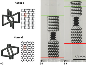
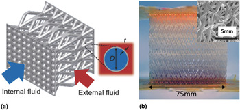
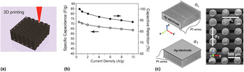
The mechanically strengthened nanostructures with ultra-low density can benefit different engineering applications. One of the recently explored applications of these architecture truss materials is in new fields such as soft robotics, where a robot's body is designed using architecture metamaterials that carry the burden of control and actuation. In one such demonstration, 3D-printed metamaterials with auxetic behavior (negative Poisson's ratio) are used as an inchworm-type soft robot for crawling through channels, and used for navigation in biomedical applications.[ Reference Mark, Palagi, Qiu and Fischer 59 ] In the design, as shown in Fig. 9(a), the two clutch pieces are made of architecture metamaterials, auxetic (top) and normal (bottom), which have complementary mechanical material properties. When the bellows are cyclically inflated and deflated, the auxetic and normal material slips forward through the channel respectively, making the robot crawl upward through a square transparent pipe. The images in Fig. 9(a) and (b) show the initial and final position of the soft robot, which is reached through expansion and contraction cycles of the bellows. During the expansion, the auxetic clutch moves upwards (green line), and the normal clutch is stationary (red). During contraction, the auxetic clutch remains fixed, and the normal clutch slides upwards. This is a passive clutch mechanism based on complementary material properties, which reduces the number of actuators from three to one. These structural designs can eventually enable compliant and robust implementation of small-scale robots with enhanced functions. In a different demonstration, architected material enables its use for thermal management application as a cross-flow heat exchanger with enhanced heat transfer.[ Reference Roper, Schubert, Maloney, Page, Ro, Yang and Jacobsen 60 ] AM has enabled fabrication of such cross-flow heat exchangers with optimized 3D cellular architecture, which comprises complex, designed fluid pathways for efficient transport. Their low thickness-to-diameter ratios compared with all existing polymer and metallic engineered heat exchangers enable efficient heat exchange that is independent of the thermal conductivity of the solid constituent material. The heat exchange core consists of fluid network made from a lattice of hollow tubes, fabricated by photopolymer waveguide and stereo lithography processes [Fig. 10(b)]. The resulting structure is coated, and the printed polymer template is removed, opening up the fluid path. These microlattice fluid networks is tested in a cross-flow configuration with hot air as the fluid flowing inside the tube network and cold air as the fluid flowing around the tube network. Other materials such as 3D graphene microstructures also offer potential for designing anisotropic thermal insulation materials. Pyrolysis was shown to be an excellent method to increase the resolution of 3D-printed carbon structures, thus enabling the cellular materials to exhibit near-ideal behavior with highest mechanical strength.[ Reference Bauer, Schroer, Schwaiger and Kraft 12 ] 3D-printed graphene structures, which offer large surface areas, low density, and superior mechanical rigidity with engineered porosity, also have potential to be used in technologies such as catalysis, desalination, and other filtration/separation applications.[ Reference Zhu, Han, Duoss, Golobic, Kuntz, Spadaccini and Worsley 33 , Reference Ma and Chen 55 ] Due to their high conductivity, high porosity, high electrochemical stability, and high elasticity, interconnected graphene networks are considered as attractive and competent materials for energy storage and conversion applications, including fuel cells, batteries, solar cells, and supercapacitors.[ Reference Ma and Chen 55 ] Graphene is an ideal candidate to host metal-oxide nanoparticles and conductive polymers, for the creation of highly efficient 3D graphene composite/hybrid electrodes, which also favors their use in supercapacitors.[ Reference Yang, Chabi, Xia and Zhu 47 ] Figure 11 shows the application of 3D hierarchical graphene aerogels in supercapacitors.[ Reference Zhu, Liu, Qian, Han, Duoss, Kuntz, Spadaccini, Worsley and Li 4 ] The 3D-printed graphene composite aerogel (3D-GCA) electrodes with periodic porosity are made of composite thixotropic ink prepared by mixing GO precursor suspension (40 mg/cm3), 4.2 wt.% graphene nanoplatelets (GNP), and 12.5 wt.% silica fillers, as well as a catalyst (R–F solution with sodium carbonate). This electrode has remarkable capacitive retention of 90% [Fig. 11(b)] when current density increases from 0.5 to 10 A/g, which is among the best values reported for carbon-based electrodes. In another experiment [Fig. 11(c)], electrically functional 3D-architectured of graphene/SiC composites is demonstrated.[ Reference Román-Manso, Figueiredo, Achiaga, Barea, Pérez-Coll, Morelos-Gómez, Terrones, Osendi, Belmonte and Miranzo 56 ] Two geometric configurations were adopted in order to measure the conductivity along the rod axis within the xy-plane (longitudinal, σ L), and in the transverse direction (xz-plane, σ T) showed anisotropic electrical conductivity with values for of 611 and 273 S/m in the longitudinal and the transverse directions, respectively. In the terms of biomedical applications, utilization of 3D-printed structures is comprehensive in bone and tissue engineering. Bone scaffolds have appropriate biologic as well as mechanical properties with designed porosity and pore interconnectivity to provide cell ingrowth and nutrition exchange in the bone; realizable with different AM techniques.[ Reference Naghieh, Karamooz Ravari, Badrossamay, Foroozmehr and Kadkhodaei 29 ] PLA is the commonly used polymer for various biomedical applications since it is a biodegradable polymer that has been approved by the FDA (Food and Drug Administration).[ Reference Serra, Planell and Navarro 36 ] Its matrix is used in combination with both polyethylene glycol and G5 glass particles, to obtain 3D fully biodegradable porous composite structures with superior mechanical and bioactive properties. Also, acrylonitrile butadiene styrene fibers are applied to create their customizable arrays, which are incorporated into a collagen scaffold for tendon repair demonstrations.[ Reference Mozdzen, Rodgers, Banks, Bailey and Harley 61 ]
(a) Auxetic and normal unit cells, (b, c) Locomotion of a soft metamaterial robot. An inflatable bellows (an air tube passes through the normal metamaterial and connects to the bottom side of the bellows) connects the normal (bottom) and auxetic (top) metamaterial clutches.[ Reference Mark, Palagi, Qiu and Fischer 59 ]

(a) Schematic representation showing unit cell lattice of 3D-printed architected material, (b) image of two interlaced lattices, with sacrificial scaffold formed via photopolymer waveguide process.[ Reference Roper, Schubert, Maloney, Page, Ro, Yang and Jacobsen 60 ]

(a) Schematic representation of 3D printing of a GO-GNP electrode structure by using a ink with shear-thinning rheology; (b) Specific capacitance and capacitive retention of 3D-GCAs calculated as a function of current density[ Reference Zhu, Liu, Qian, Han, Duoss, Kuntz, Spadaccini, Worsley and Li 4 ]; and (c) Schematics representation of both set-ups for s measurements of the scaffolds corresponding to the longitudinal (σ L) and transverse (σ T) structure orientations, and picture showing the actual rod arrangement with axis of coordinates for σ L and σ T measurements.[ Reference Román-Manso, Figueiredo, Achiaga, Barea, Pérez-Coll, Morelos-Gómez, Terrones, Osendi, Belmonte and Miranzo 56 ]

Conclusions
This review gives a selective overview and highlights about recent developments in advanced manufacturing of small-scale mechanically reinforced 3D-architected structures with dimensions that span to nanometers. The advantage of well-defined architecture and small-scale size effect can be propagated toward generating unique class of materials with supreme mechanical strength at ultra-low densities. With the various available fabrication techniques, 3D printing is capable of creating unique functional structures with well-controlled structural parameters, which can open up tremendous opportunities in design and fabrication of novel devices. Structures like, 3D-printed periodic carbon structures were able to achieve very high modulus with respect to their extremely low bulk density. In addition, the stereolithography printed 3D graphene oxide structures with good mechanical properties of improved strength and ductility were demonstrated. From the results of compression tests of these architected structures, the failure model can be estimated and accordingly, the design can be altered to generate structures with higher mechanical strength. So far, 3D architectures have been printed with minimum feature sizes of few nm from multiple classes of materials, yet further research in both design and materials is required to yield 3D architectures with an unimagined performance. As new methods emerge and mature, fabrication of complex architectures with high resolution is achievable and the new optimized designs of multiscale, cellular architectures composed of multiple materials in the composite form is expected to yield more breakthroughs in the future. Thus, the 3D architecture-based structural materials is a growing field and has the potential to allow for development of metamaterials for revolutionary engineering applications requiring extreme mechanical properties.
Acknowledgments
This work received financial support from Discovery Accelerator Supplement Grant 493028-2016, funded by Natural Sciences and Engineering Research Council of Canada (NSERC).