The physics of indentation of metals by wedges, fundamental to hardness tests and assessment of mechanical behavior,[Reference Oliver and Pharr1–Reference Pharr, Herbert and Gao4] has a long history of theoretical and experimental investigation.[Reference Hill, Lee and Tupper5–Reference Hirst and Howse9] Theoretical tools for studying wedge indentation include slip-line fields[Reference Hill, Lee and Tupper5] and cavity models.[Reference Johnson10] Experimentally, deformation patterns have been obtained by studying changes in the shape of an inscribed rectangular grid[Reference Hill, Lee and Tupper5] or using microstructural features as markers.[Reference Chaudhri11, Reference Chaudhri12] These experimental techniques are, however, limited in one or more of the following aspects: spatial resolution, temporal resolution and field of view. More recently, electron microscopy (electron backscatter diffraction, EBSD) has been used to determine lattice rotations in indentation of single crystals,[Reference Kysar, Gan, Morse, Chen and Jones13] but not plastic strain or other measures of deformation. Further, given the complexity of indentation, slip-line fields, while useful, provide an over-simplified view of the deformation field. With these motivating factors, we use a combination of high-resolution imaging, particle image velocimetry (PIV) and finite-element analysis (FEA) to study wedge indentation strain fields with enhanced spatial and temporal resolution.
Noteworthy prior studies of wedge indentation using FEA and related simulation include conventional elastic–plastic FEA,[Reference Cai14, Reference Jayadevan and Narasimhan15] discrete dislocation plasticity for films[Reference Balint, Deshpande, Needleman and Van der Giessen16] and polycrystalline aggregates,[Reference Widjaja, Van der Giessen and Needleman17] FEA using strain-gradient plasticity[Reference Fredriksson and Larsson18] and crystal-plasticity-based FEA for face-centered cubic single crystals.[Reference Saito, Oztop and Kysar19] Importantly, however, the application of FEA to indentation by narrow angle wedges (and cones) has been problematic and largely ignored. A recent attempt to resolve problems in simulating narrow angle indentation (cone) is noteworthy; it uses a needle-like protrusion from the indenter tip and removes a thin layer of material adjoining the symmetry axis from the specimen.[Reference Hazell20]
In fact, the aforementioned problem in FEA arises due to an unrealistic constraint generated by the commonly used half-symmetry boundary conditions (b.c.). This may be explained as follows. Consider a hypothetical mode of deformation in which a surface material point “C”, which is initially almost directly below the wedge tip (|x| ≈ 0, y = 0), is pushed away to one side early during the indentation and remains close to the free surface as the indentation progresses. A small rectangular element OABC with OA lying initially on the symmetry line will thus experience extreme stretching and large, unphysical strains along the interface due to the symmetry constraint on the face OA. This problem cannot be resolved by using a finer mesh; refinement would merely lead to mesh-dependent (possibly, divergent) strains. Instead, consider replacement of the symmetry b.c. on the horizontal displacement u along the indentation axis (y-axis):

by a “weak” form of the b.c. (see schematic in Fig. S1)

where ∆ is the indentation depth. The symmetry line is kept shear free, i.e., τ xy|x=0 = 0 if y < 0, for both types of b.c. Note that the strong form of the b.c. is a special case of the weak form and the weak b.c. defines, in effect, a frictionless contact that prevents flow of material across the symmetry line. The weak form is a perfect substitute for the strong form as long as points on the y-axis do not exhibit significant lateral flow. If u along x = 0 is large, the solution using the weak b.c. is approximate because the motion of points away from the symmetry line would be resisted by internal forces to some extent. Crucially, the weak b.c. removes the unphysical stretching described above, enabling FEA of narrow angle wedge indentation.
Annealed oxygen-free high conductivity (OFHC) Cu specimens (76.2 mm × 25.4 mm × 9.5 mm) were indented at 0.3 mm/s using high-speed steel wedges of apical angles (2α) of 30, 60, 90 and 120°. A transparent glass block was used to restrict out-of-plane flow and establish plane strain. During indentation, the specimen was imaged through the glass at 30 fps using a CCD camera–optical microscope assembly, capturing an area of 5.3 × 4.0 mm around the indenter, with spatial resolution of 0.0033 mm/pixel. Displacement/velocity fields of material flow were obtained by image correlation (see Supplementary movie files) using PIV, from which strains and strain rates were calculated.[Reference Murthy, Huang and Chandrasekar21, Reference Sundaram, Guo, Murthy, Saldana and Chandrasekar22]
The ABAQUS explicit solver was chosen for its robust contact analysis capability. The indenter was modeled as a rigid body, whereas the Cu specimen was modeled as a rate-independent, elastic–plastic material with isotropic hardening (Fig. S2). The specimen was meshed using four-noded plane-strain elements with reduced integration. The simulation was time scaled by a factor of 250 over the experiments to provide a good compromise between solution time and accuracy. The outer dimensions of the specimen were chosen to be large enough (≥20∆) to simulate a semi-infinite specimen (Fig. S3). The mesh size is chosen to give 140–180 specimen elements along each side of a strain interrogation region (typically 2∆ × 2∆ in extent). The wedge–specimen contact was modeled using a friction coefficient μ = 0.5, with maximum shear stress τ max = Y/√3 with Y chosen to be the midpoint of the uniaxial yield curve. The weak b.c. were modeled using a frictionless contact extending to a depth ∆; using μ = 0 here ensures that τ xy|x=0 = 0.
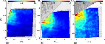
Figure 1 shows measured equivalent plastic strain fields (ɛ p) plotted on depth-normalized axes, derived from high-resolution image sequences of the indentation such as shown in the Supplementary videos. Three distinct modes of deformation are seen depending on 2α, two of which exhibit high strains and strain localization. In narrow angle [2α = 30°, Fig. 1(a)] wedge indentation, points initially beneath the indenter are pushed to one side early during the indentation, and a region of strain localization develops around these points as the indentation progresses. The region of maximum strain lies on the interface and close to the free surface. We call this mode of indentation “separation”. In contrast, for a wider wedge [90°, Fig. 1(b)] the strain localization is of a distinctly different kind. A point initially below the indenter remains nearly so during indentation, but the deformed region itself is confined, leading to a localized region of high ɛ p below the wedge tip. This mode will be called “cutting”. At even wider angles [120°, Fig. 1(c)], the strain localization is much less pronounced, and the pattern is the well-known one of radial compression. In this case, the overall deformed region is quite large and extends to about y = −3∆ for 2α = 120 [Fig. 1(c)], but essentially ends at y = −∆ for 2α = 30 [Fig. 1(a)]. The difference in strain localization between 30 and 90° wedge indentation shows that identifying a single non-radial mode of deformation (historically termed as “cutting”) as in the past[Reference Hill, Lee and Tupper5, Reference Mulhearn7] is inadequate. The 2α range associated with this traditional “cutting” pattern exhibits two distinct deformation modes, “separation” at smaller values of 2α and “cutting” at larger values of 2α.
Plastic strains obtained from experiments for wedge angles (2α) of (a) 30°, (b) 90° and (c) 120°. The strain patterns correspond to (a) separation, (b) cutting and (c) radial compression.

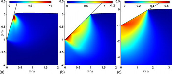
Figure 2 shows the ɛ p field obtained using FEA for the same set of wedge 2α and plotted on similarly normalized axes. A comparison of strains in FEA and experiments shows good agreement, and establishes the efficacy of the weak b.c. in simulating narrow (30°) as well as wide angle indentation. Note that μ is difficult to control in experiments and accounts for the minor disagreement between the experiments and FEA. Also, PIV is difficult to perform at locations very near interfaces. Interestingly, both FEA and PIV results indicate that the “cutting” mode (90°) provides the largest possible ɛ p. This is even larger than the ɛ p seen in the “separation” mode with a narrow wedge (30°). Both sets of results show that the peak ɛ p is smallest for 120° radial compression, about 0.64.
Plastic strains obtained by FEA with weak b.c. for wedge angles (2α) of (a) 30°, (b) 90° and (c) 120°. The strain patterns correspond to (a) separation, (b) cutting and (c) radial compression.

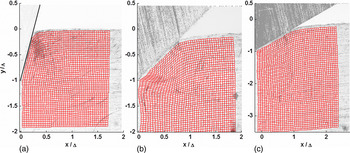
Figure 3 depicts the final shapes of initially rectangular grids after indentation by wedges of different 2α. Such grids are commonly used to illustrate deformation modes in experiments, but in contrast to physically inscribed grids, PIV allows the tracking of grids of any size up to the limit of resolution. The 120° pattern [Fig. 3(c)] agrees closely with the well-known radial compressive pattern.[Reference Haddow8] Note the localized deformation beneath the indenter tip for 2α = 90° [Fig. 3(b)]. For the same grid size, this localization is barely detectable for the narrow angle wedge indentation [Fig. 3(a)]. An even coarser grid would miss the strain localization altogether and provide a misleading picture of the deformation. This is of particular concern in experiments; for example, the inscribed grid used by Hill et al.[Reference Hill, Lee and Tupper5] with their narrow wedges is too coarse for this reason.
Deformed grid patterns for various wedge angles (2α) (a) 30°, (b) 90° and (c) 120°.

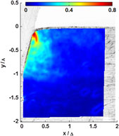
In the simulations, it was noted that the lateral flow (i.e., in the x-direction) even with the 30° wedge was very small, no more than a fraction of the element width. Taken in conjunction with the good agreement between FEA and PIV strains in Figs. 2 and 3, this shows that the effect of “cohesive” forces along the symmetry line on the deformation may be safely ignored for 2α = 30° and also that the weak b.c. are highly effective. For wide-angle wedges, where the FEA can also be performed successfully using the strong b.c., use of the weak b.c. produces consistent results. This is seen in Fig. S4, wherein the ɛ p FEA fields for 2α = 120° using weak and strong b.c. are essentially indistinguishable.
The application of weak b.c. along the y-axis to a depth of ∆ resembles a frictionless crack with crack-face interpenetration prevented by contact. The major difference is that during indentation, material ahead of the instantaneous wedge tip along OY (up to a depth of ∆) is still free to flow laterally (u ≥ 0). With a crack, points ahead of the crack tip cannot experience such lateral flow unresisted.
The highly localized strains generated by narrow angle wedge indentation could be of value to probe strain gradient effects, since the localization is associated with large strain gradients and tighter limits on the accommodation volume for geometrically necessary dislocations. Further, the different spatial localizations of ɛ p, shear and pressure using wedges of different 2α could be used to study phenomena such as pressure-driven phase change in materials,[Reference Pharr, Oliver and Harding23] ductile to brittle transition and microstructural changes. Owing to close similarities between wedge and cone indentation, the weak b.c. should facilitate simulation of narrow angle cone indentation. A comprehensive report of the deformation fields for a wider, more finely sampled range of wedge angles and different friction coefficients will be presented elsewhere.
Acknowledgments
NSF grants CMMI 1130525 and 1031056 are acknowledged for support.
Supplementary materials
For supplementary material for this article, please visit http://dx.doi.org/10.1557/mrc.2012.6