1.0 ADDITIVE MANUFACTURING IN UNMANNED AERIAL VEHICLES (UAVS)
The advent of low-cost and light weight autonomous control systems, rare earth magnet electric motors and powerful LiPo batteries has resulted in a huge surge in the development and use of small, lightweight UAVs (commonly referred to as drones). While the initial developments of UAV technology were the preserve of the military and security agencies, the vast majority of these systems are now sold into the hobby market, in the form of small multi-rotor systems carrying small cameras. More recently, a number of commercial and scientific sectors, ranging from farming to plant maintenance to disaster monitoring to photography, have taken up such technologies in significant numbers, see for example Refs 1 and 2.
At the same time, a number of new manufacturing technologies have impacted on developments in this field. In particular, the availability of low-cost additive manufacturing (3D printing) has provided design freedom to those wishing to make specialist UAVs in modest quantities for research and scientific purposes, or for initial prototyping of systems before committing to large scale manufacture. A thorough and recent review of the use of additive manufacturing and its use in UAV design is provided by Ref. 3. They cite, for example, the work of the authors in Ref. 4 who describe the use of 3D printing to create a small scale test model for wind-tunnel testing and validation. Also, the authors of Ref. 5 who recount their experiences with a larger maritime surveillance UAV which includes substantial elements of 3D printed structure. The first fully 3D printed UAV flown was the Southampton University Laser Sintered Aircraft (SULSA), which was developed to demonstrate what was possible with this newly emerging combination of technologies in a fixed wing format(Reference Marks6). Since that time, the SULSA aircraft has been used for a number of further studies, the latest of which is the subject of this article.
2.0 SOUTHAMPTON UNIVERSITY LASER SINTERED AIRCRAFT (SULSA)
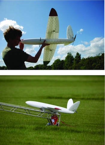
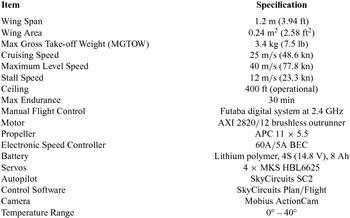
The SULSA is an all laser sintered, battery powered sub-4 kg UAV with on-board GPS enabled autopilot (see Fig. 1). Basic details of the system are set out in Table 1. SULSA was originally designed, built and flown to demonstrate the possibilities of using as much 3D printing in a UAV airframe as possible. This method of manufacture enabled the creation of complex geometry, including elliptical wings and geodesic structural reinforcement throughout. SULSA was not initially designed to carry a payload or to be operated other than from its catapult to landing on grass strip runways.
SULSA airframe illustrating SLS structure and catapult mounting.

SULSA UAV specifications

It was, however, designed to allow completely autonomous pre-planned operations with the capability for in-mission flight-plan updating. SULSA can be operated in MANUAL, ASSISTED or AUTOPILOT modes. MANUAL mode allows the pilot to directly command the control surfaces. ASSISTED mode allows the pilot to dictate intended direction, speed, height, etc.., without the need to actually directly direct the ailerons and ruddervators – this permits control at ranges where the aircraft is difficult to see. In AUTOPILOT mode, SULSA follows a pre-programmed route and can be controlled via a ground control station. Autopilot flight control plans are typically initiated when the autopilot senses the accelerations caused by release of the catapult or can be set to hold a constant airspeed and heading until a specified altitude had been reached, after which waypoint following begins. These can continue all the way to final shutdown after landing. The 2.4 GHz Futaba primary radio control system used for close-in manual flight has a range of approximately 1 km while the autopilot has its own dedicated 633 MHz telemetry channel to the ground control station with a range of approximately 10 km. The autopilot telemetry system enables monitoring of the aircraft's position in real time as well as on-board health monitoring. It can also be used to upload changes to any pre-programmed guidance instructions.
The original airframe was flown a number of times to establish its airworthiness and suitability for autopilot control. The most recent variant of the system incorporates a number of design improvements including the use of carbon fibre reinforced hinge pins for the control surfaces and a nose mounted video camera. Waterproofing was limited to enclosing the internal avionics within a waterproof bag and using water-resistant grease to protect and salt-proof the servos and their linkages. The pitot system also included an elongated internal tube with multiple spirals to reduce the likelihood of water reaching the internal pressure sensor. The external pitot tube was heated by making it of copper and soldering it directly to the heatsink for the internal speed controller. Future variants will incorporate high-definition video radio downlinks to provide live data from the on-board camera and enhanced waterproofing.
3.0 MARITIME FLIGHT TRIALS
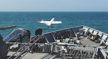
To assess the suitability of the basic SULSA concept for maritime operations, a series of flight trials have been carried out with the support of the UK's Royal Navy. Initially, in 2015, a simple launch from ship and recovery to shore trial was conducted from HMS Mersey while positioned close to the southern coast of the UK (see Fig. 2). This demonstrated the feasibility of ship board catapult launch to a pre-programmed, autopilot controlled flight plan. Landing was carried out by a shore-based operator onto the adjacent beach. Following this successful test, it was decided to embark on a more ambitious set of trials in the Antarctic from HMS Protector. These flights were intended to establish the capabilities of the system when operated at low temperatures, with recovery at sea and long endurance flights at extended ranges from the ship using a suitably declared danger area. Execution was conducted as a trial under the authority of the Royal Navy's Maritime Operational Test and Evaluation (OT&E) Board who authorised the trial to proceed.
SULSA launching from HMS Mersey – 21 July 2015.

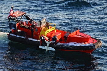
During the trials, SULSA was launched from the HMS Protector to conduct visual surveys as directed by the commanding officer in the vicinity and ahead of the ship prior to being recovered by ditching in the sea alongside. It was then recovered by a sea boat. The choice of sea boat recovery was dictated by the health and safety requirements of the ship rather than by any limitations of the airframe or difficulty in landing the aircraft directly on the ship into a net or other compliant structure. By landing in the sea well clear of the ship and sea boat, risks to personnel were reduced to their lowest possible extent, albeit at the cost of some inconvenience and possible damage to the airframe. Clearly, an on-board recovery would be more practicable and for such a small airframe landing on such a large flight-deck area, easily accomplished. A series of SULSA airframes were made available for use during the trial with the intention that, where possible, they would be re-used following recovery. The low cost of the system allowed multiple airframes to be supplied for the flight trials. To achieve the trial objectives, a minimum of three flights were required with the survivability of the UAVs following recovery determining if further flights would be possible.
The test flights were planned in conjunction with a formal safety assessment which contained detailed technical and operational aspects of the UAV.
4.0 TRIAL OBJECTIVES
The trial objectives defined at the outset of the project were:
-
• Sufficient aircraft performance,
-
• Successful aircraft launch,
-
• Established on climb-out post-launch,
-
• Established at selected altitude on selected flight path,
-
• Accurate maintenance of flight path following pre-planned waypoints,
-
• Accurate over-flight of Terminal Waypoint (TWP),
-
• Successful handover to Unmanned Air System (UAS) Operator (i.e. pilot using RC controls),
-
• Successful ‘soft’ ditch in sea,
-
• Utility of media in conducting ice survey for navigation,
-
• Re-usability of aircraft.
The trial objectives were met by an incremental approach to testing, by determining the baseline serviceability and operational capabilities of the UAV and its interfaces with the ship before the aircraft's first flight. The total number of flights possible during the trial was determined by the number of airframes available, their re-usability, the number of launch cradles available and the available weather windows. There were three SULSA UAVs embarked for use during the trial. Their reusability was determined by the survivability of the UAV following ditching in the sea. There were six launch cradles embarked for the trial. During a normal launch, these detach after the aircraft has left the catapult launcher and it was expected that they might be lost overboard. However, it might be possible to capture them depending on the launch position in which case they could be re-used.
The ground and flight phases followed the incremental ‘crawl, walk, run’ philosophy using a ground test phase followed by a flight test phase.
5.0 GROUND TEST PHASE
The ground test phase was used to conduct a baseline assessment of the effectiveness of the basic procedural and technical capabilities of the UAV to shape the flight test phases of the aircraft. The following points were assessed during ground testing:
-
• Aircraft serviceability following transit to ship.
-
• Location of launcher and method of attachment to deck/super-structure.
-
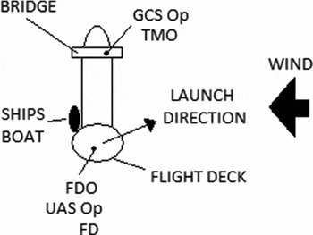
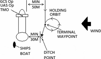
• Location of personnel. Figures 3 and 4 provide an initial indication where it was planned that all project personnel would be located.
-
• Communication between all positions (i.e. bridge, flight deck/launch position and the ship's boat).
SULSA launch template.

SULSA recovery template.

Aircraft performance was established to determine any differences between performance in the temperate climates that SULSA has previously flown and Antarctic temperatures. The aircraft was ground tested warm and pre-cold soaked to determine the effects on:
-
• Engine performance,
-
• Battery Life,
-
• Servo operation,
-
• Control surface movement,
-
• Communications with Skycircuits PLAN Ground Control System (GCS) and Radio Control (RC) handset,
-
• Electromagnetic Interference assessment (effect of HMS Protector's emitters on SULSA),
-
• Route planning and entry to GCS,
-
• Ability to upload route plan to SULSA.
6.0 FLIGHT TEST PHASE
The flight test phase was broken into three elements as discussed in the following paragraphs. Ideally, each phase would consist of two flights each; however, due to the minimum expectation of three and maximum of six flights set by airframe availability, it was assumed that there might be only one of each unless the survivability of the UAV allowed more.
-
a. Basic Operation. Initial flight testing aimed to ensure the basic technical capabilities of the UAV. The first flight aimed to test the launch and recovery procedures in addition to the ability to accurately track the movement of the UAV on the GCS. Any identified shortfalls in the basic operation could then be used to shape the operational employment test phase. If significant issues were identified, the flight could be re-flown or the risk accepted following mitigation action (this would predominately be determined by the re-usability of the aircraft). The basic operations were planned to include:
-
i. Successful launch without recourse to MANUAL or ASSISTED control
-
ii. Capture pre-planned route
-
iii. Follow simple pre-planned route within Visual Line Of Sight (VLOS)
-
iv. Over-fly TWP – enter holding orbit
-
v. Transfer to ASSISTED control and controlled ‘soft’ ditching
-
vi. Recovery of aircraft
-
vii. Extraction of media and assessment of media quality
-
b. Basic Operational Employment. This phase expands on the basic operation to start to look at the operational employment of the UAV and its ability to capture video footage along the aircraft's track. Flights in this phase would be planned to fly further from the ship up to the maximum anticipated VLOS (up to approximately 1 km from the ship) and assess the system at two distinct altitudes. It was accepted that the aircraft might not actually be visual for the whole flight and a determination can be made by the command on HMS Protector whether a route correction should be updated to bring the aircraft back within visual acquisition. The prime aim of this phase of flight test phase would be to assess the utility of received video footage and its relation to features on the ground/ice.
-
c. Advanced Operational Employment. This phase would take the basic employment and extent to the maximum BVLOS range of 1.5 km. It was intended that the project team would be tasked by HMS Protector Command with conducting a survey of an area of interest to the ship. The route is to be planned and flown accordingly with the analysis of the resulting video used to determine the utility of the SULSA UAS as a whole.
7.0 HMS PROTECTOR
HMS Protector is the Royal Navy's ice patrol ship and the test flights were aimed at gaining understanding of how such a system might aid the ship in its normal operational duties as well as assessing further the capabilities of the SULSA system. During launch and recovery, the ship would be in dynamic positioning mode (with orientation depending on prevalent wind to ensure Wind Over Deck (WOD) for SULSA launch). It would be preferred that minimal speed is employed due to the short flight duration of the SULSA flight and the expected relative position of the TWP which would be ideally located off the bridge wing (although updates could be made if required). All non-urgent radio transmissions were halted during flight trials.
SULSA can be launched with a maximum headwind component of 12 m/s (25 kn) within 25° of wind direction. A headwind component of 3 –8 m/s (6-15 kn) can aid SULSA launches during calm conditions.
8.0 LAUNCH TEMPLATE
Figure 3 illustrates the typical template for a SULSA launch and shows the relative launch direction of the aircraft, a figurative position of the ship's boat and the anticipated positions of all trial personnel. It also shows an initial estimated position of the launcher. Once launched, the UAV would be set to attain a nominal altitude of at least 300 ft. above sea level at its first waypoint at which point it would commence following its pre-planned route.
9.0 RECOVERY TEMPLATE
Figure 4 illustrates the typical template for SULSA recoveries with the anticipated positions of project personnel: the UAV to approach its TWP on a track parallel to the ship's course. The TWP would be at least 50 m from the ship's side and at an altitude of at least 150 ft.; in order to ensure the UAV approaches TWP parallel to the ship, a waypoint (TWP-1) would be established. Once the UAV over-flies the TWP, it would then immediately enter a holding orbit away from the direction of the ship. It would stay in this orbit until the UAS Operator (located on the bridge wing) had visually acquired it – once it is parallel to the ship again (at its closest point), the UAS operator would take control of it in MANUAL mode and fly the aircraft to a soft ditch in the sea beside the ship ensuring that it did not get closer than 30 m. The ship's boat would then be tasked to recover the UAV using directions from the bridge.
10.0 LAUNCH SUMMARIES AND FLIGHT RESULTS
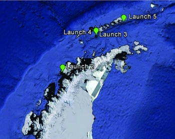
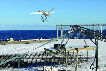
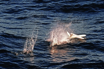
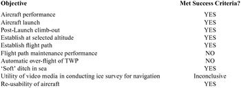
Five launches were attempted during the flight trials series which are summarised next. Figures 5–8 show the locations of the successful launches, the launch arrangements, aircraft landing and airframe recovery by sea boat. Table 2 lists the locations of the ship at the start of each of the successful launches, while Table 3 summarizes the trial objectives and outcomes.
Launch One – 24 March 2016
Launch locations.

SULSA launching from HMS Protector – 3 April 2016.

SULSA landing alongside HMS Protector – 3 April 2016.

SULSA being recovered by HMS Protector's ship's boat – 3 April 2016.

Launch locations

Summary of trial objectives

10.1 Synopsis
An unsuccessful flight with the aircraft failing to launch successfully.
An inauspicious start. Despite meticulous preparation, a launch failure wrote off the first airframe, though the avionics were reusable. Video indicated that this wasn't due to the trolley derailing, but instead failing to detach cleanly from the aircraft. After some modifications to the launch trolleys (and replacing the catapult bungee/raising the catapult for good measure), there were no further problems with the launches.
10.2 Test conditions and results
On launch, the cradle did not leave the end of the launcher evenly resulting in the aircraft impacting the deck approximately three meters from the end of the launcher. The un-even launch was assessed to be due to movement of the ship caused by sea swell and wind speeds above 20 kn. The airframe was unusable but its avionics were assessed as being re-usable.
The launch ship was stationary in the water (in dynamic positioning). Wind was 20 kn on aircraft heading (GREEN 90) with sea state 2 and a light swell of +/–2°. The incident has illustrated the sensitivity to the launch system to the ship's motion accentuated from the flight deck (noting that the flight deck is approximately 15 metres above sea level and therefore more prone to ship movement).
Launch Two – 29 March 2016
10.3 Synopsis
Successful flight giving confidence for EVLOS flight.
The first successful flight. The intention was to assess the accuracy of navigation by flying a series of waypoints in close proximity to the ship. Though navigation was not perfect (with the aircraft appearing to drift progressively closer to the ship), it gave enough confidence for the EVLOS flights. Some good on-board video was obtained.
10.4 Background
Following the failure of the first flight, a number of measures were taken to reduce the likelihood of causing a repeat performance. These included minor modifications to the launch cradle, mounting the launcher on some trestle tables to increase deck clearance and changing the launcher bungee. In addition, the launch was conducted into wind of <4 kn with negligible gusts with the ship in a static position in dynamic positioning.
10.5 Test conditions and results
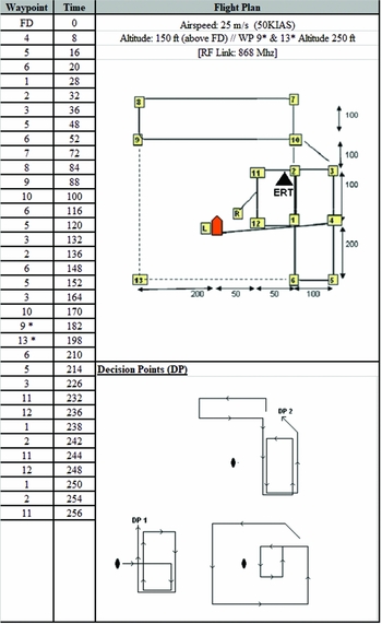
The flight was conducted using the template shown in Fig. 9. The waypoints were planned using a relative position to the ship's location and aligned to the ship's head bearing. However, it became evident on launch that the autopilot was not quite aligned to this heading and although it attempted to follow the pre-determined flight plan, its accuracy slowly decreased. At decision point 2, it was determined not to allow the flight plan to proceed on the 3rd phase (an orbit of the ship) as the flight path took the aircraft to approximately 50 m of the ship rather than the planned minimum of approximately 200 m at this point. The UAV was transferred to MANUAL control and landed safely on the water. The aircraft was recovered safely and efficiently by the ship's boat.
Launch two flight profile.

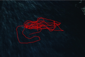
Flight time was approximately 5 minutes 20 seconds. The media was recovered from the UAV and provided good quality footage of the flight. The flight track recorded by the aircraft GPS is shown in Fig. 10 but this track was corrupted by intermittent GPS location failures in the logging process.
Launch two flight track. Note that this is based on the GPS positions logged by the autopilot and is not representative of the flight path followed by the aircraft in this case.

10.6 Analysis
It is assessed that the deviation from the planned flight path was caused by a combination of two things: (1) Incorrect interpretation of reference heading by the UAV following transfer of the route i.e. the orientation of the route did not accurately reflect the actual heading of the ship at the time of launch, and (2) the relative tightness of the planned route caused the aircraft to continually over-fly its intended waypoint due to inaccuracy in track maintenance thought to be caused by the low feedback rate autopilot steering commands. The restricted accuracy of route maintenance compounded the initial heading orientation errors. Note that the tightness of the route was required to maintain the aircraft within VLOS – it is not assessed that this would be an issue for Extended VLOS (EVLOS) flight when minimal waypoints would be planned.
Initial evaluation indicated that the aircraft airframe was reusable, but not some of the avionics/engine components, although the autopilot, receiver, servos and motor appeared to be functional.
Launch Three – 31 March 2016
10.7 Synopsis
Good flight demonstrating excellent aerodynamic performance but somewhat let down by poor systems performance and non-recoverable video of flight.
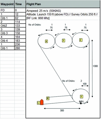
The aim for this flight was to perform a series of orbits over an abandoned research base. For this, absolute rather than relative waypoint positions were used, though significant discrepancies between the ship's navigation system and the SkyCircuits Plan software for the same coordinates was observed. As a result, SULSA did not fly exactly where it was meant to, and on top of this, the camera did not save the video file (most likely due to salt water ingress on landing – clearly a fully waterproof camera would be a more viable but also more expensive solution to this problem). Otherwise, it was a successful first EVLOS flight.
10.8 Background
Following on from the first successful flight, this profile was intended to act as a standard format for providing a survey pattern in a direction determined by the ship's command.
10.9 Test conditions and results
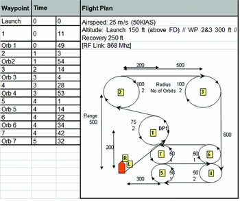
A survey area was identified within Deception Island with the ship in dynamic positioning approximately 1.2 nm from the nearest point of land. The flight was conducted using the template shown in Fig. 11. The latitude/longitude of the survey area and the ship's location was provided as input to the GCS Skycircuits PLAN tool. It was noticed that the range and bearing given between the survey area and the ship were significantly different on PLAN and the ship's own systems. (GCS gave 1,325 yards at 223°, whereas the ship systems gave 1,600 yds at 216°.) Waypoint 3 was specified as the survey area and flanked by waypoints 2 and 4 with similar search orbits. To mitigate the potential variation in the survey area direction it was decided to add an additional search orbit after waypoint 4 to ensure that the survey area was covered – noting the limitation of maximum range of 1,500 m. Prior to launch, the ship was manoeuvred to give the correct WOD and the orientation of the initial and TWP adjusted accordingly (300 m at GREEN 45). Note that due to the max range limitation, the aircraft did not actually over-fly the survey area – the intention was to try and gain video footage of it.
Launch three flight profile.

The aircraft was launched into wind GREEN 90 14 kn with 1 – 2 kn gusts and assessed as an efficient and stable launch. After attaining the cruise altitude, the aircraft turned to its initial waypoint and conducted its planned two orbits prior to departure to the survey area. The aircraft was visual throughout the flight, although its orientation at its furthest point was only detectable by aided vision. As the aircraft conducted its four orbits it became obvious that it covered the search area in only the first orbit (waypoint 2 rather than the planned waypoint 3), with the remaining search orbits increasingly further away from it (as per the plan).
It was intended that the aircraft would only orbit each survey (2,3,4,5) waypoint once, however, it was noticed that at waypoint 5, the UAV entered a second orbit. The GCS operator then edited the route to command the UAV to return to its TWP. The UAV responded immediately to the command and on arrival at the TWP entered its holding orbit. The UAS operator took control in MANUAL for a soft ditch in the sea without incident.
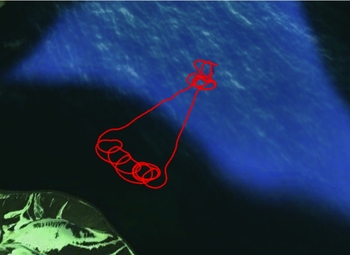
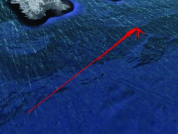
Flight time was approximately 4 minutes 50 seconds. Unfortunately, the media recovered from the UAV was found not to have recorded the actual flight. The flight track recorded by the aircraft GPS is shown in Fig. 12.
Launch three flight track.

10.10 Analysis
The aerodynamic performance of this flight was good. Flight path maintenance seemed good especially considering the much higher wind speed. It is obvious that without the requirement to fly a tight, multiple-waypoint route, the UAV stability was satisfactory.
It is assessed that the variation of information obtained from Skycircuit's PLAN and the ship's systems is due to different World Geodetic System Models. The conclusion is that the latitude/longitude co-ordinate system used by PLAN (and hence programmed to the UAV autopilot) is erroneous and resulted in the displacement of the search area, mitigated by the addition of an extra orbit to ensure it would be covered. It was concluded that all future flights would be completed by the reference method of plotting waypoints.
The multiple orbit of waypoint 5 was found to be an error in planning. It is required that the number of orbits be input in a dialog box during the planning process; if the number input is left as 0, then an infinite number or orbits will be conducted – this was found to be the case. This was an oversight in planning and not due to autopilot error. On the positive side, the GCS commands to the UAV proved the ability to update UAV route geometry commands during flight.
It was noted that although the latitude/longitude of waypoints could be entered (and accepted) by the GCS PLAN software, it was not possible to enter (exactly) the home (i.e. ship's location) without access to the Internet. Therefore, the exact position had to be derived by the GCS on power-up of the aircraft. Without further analysis of the software functionality, it is unknown what errors would be introduced by this system. It was further observed that there were limitations in the ability to conduct post flight analysis of the telemetry – to observe the flown route, Google Earth is required, which necessitates an Internet connection.
It is unknown why the camera system did not record the flight. The UAV is designed to record continuously when powered up and therefore does not require to be ‘switched-on’. It is possible that the loss of power on landing caused the camera to stop functioning immediately and thereby prevented the media file from being ‘saved’. It is inevitable that technical issues like these will occur due to the nature of use and remain a risk of reoccurrence without a redesign of the UAS. Future variants with a live video downlink would overcome this issue.
Initial evaluation indicated that the aircraft airframe was reusable, however, as per the previous flight, some of the avionics components were not.
Launch Four – 1 April 2016
10.11 Synopsis
Successful flight providing excellent camera footage despite unreliable Radio Frequency (RF) link and periodic loss of visual contact with the ship.
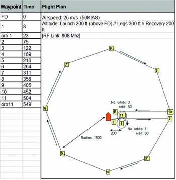
This flight was a circuit around the ship at a radius of 1.3 km with the aim of capturing footage of the Deception Island crater. This time, the camera was set to split the video into three-minute segments to limit the amount of footage that might be lost. The flight went exactly as expected, though tentative visual contact and a period without RF link caused some anxiety and the command was given to take manual control and ditch as soon as SULSA was within visual range. As a result the last part of the video that included the return to the ship was lost, though some spectacular footage was still obtained.
10.12 Background
This flight was a departure from the ice navigation focus mainly to take advantage of the unique surroundings of Deception Island. The main intent was to assess the RF link capability and the camera performance.
10.13 Test conditions and results
The test flight intended to expand on the achievements of previous flights. An octagonal flight path was designed around the ship in an attempt to video the internal perimeter of the island's crater at the maximum height available (400 ft). This was planned to be the longest flight at over double the duration and pushing towards the maximum cleared range (1,500 m). The flight was conducted using the template shown in Fig. 13. Shortly before launch, the range was reduced from 1,500 m to 1,300 m in order to accommodate the ship's position and allow a safety margin from the nearest point of land.
Launch four flight profile.
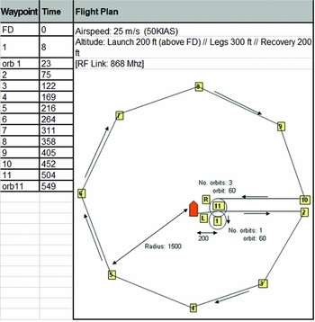
The route was planned using the reference method of plotting waypoints with particular effort to ensure correct orientation with the ship's head. The outbound transit to 1,500 m was designed to be as near to 90° from the ship's head as possible to assess if the orientation was correct. The autopilot safety perimeter was set at 1,500 m (if route maintenance failure occurred and the UAV reached this range, the aircraft would automatically return to its Emergency Return Point (ERP) at G45 300 m where it would orbit until ditched).
The aircraft was launched into wind GREEN 90 23 kn with 1 – 2 kn gusts. Just after leaving the launcher (with cradle detached), the aircraft experienced a large left wing drop (approximately 40°) due to wind gust but recovered immediately in AUTOMATIC control without loss of altitude. After attaining the initial cruise altitude of 200 ft (above sea level), the UAV conducted its planned single orbit prior to departure to its initial waypoint 1,300 m from the ship, climbing to a cruise altitude of 400 ft (300 ft above sea level). It was obvious on the route out that wind was notably stronger than previously experienced, however the aircraft could be seen to crab into wind without any problems. The route was designed to take the UAV behind the ship initially, and it was expected that the RF link would drop out at some point due to obscuration of the antenna (which was located on the Starboard (STBD) bridge roof). Once the aircraft came out from the RF blind arc (RED180 to RED90), the GCS failed to reacquire the telemetry downlink from the AV. Nevertheless, the UAV maintained its planned route and arrived at its TWP to enter a holding orbit prior to the UAS Operator taking MANUAL control and conducting a safe ditch in the sea near the STBD quarter. At various points throughout the flight, the ship lost visual contact with the UAV due to unsuitable background contrast or sun blinding. When the UAV was in view, it was always at its planned position in the route and approximately on schedule for each waypoint.
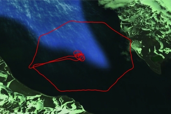
Flight time was approximately 10 minutes 20 seconds with a route length of approximately 12 km. The media recovered from the UAV provided approximately 8 minutes of flight footage, however failed to record the last 2 minutes of the flight. The flight track recorded by the aircraft GPS is shown in Fig. 14.
Launch four flight track.

10.14 Analysis
Again, the aerodynamic performance of the aircraft was good. The autopilot handling including flight path maintenance in a higher wind speed was also good; however, the video footage still shows continual, large (+/–15°) lateral flight perturbations which required corrections which looked highly inefficient – this illustrates that the Flight Control System (FCS) control laws can be optimised for a significantly smoother and more stable flight (especially given the large control surface areas) which would provide a better platform for the camera capability.
The aircraft's route maintenance in the absence of an RF link proved the autopilot's autonomous capability; however, the ship's command team expressed understandable concern that there were periods of flight where the GCS Operator had no control over the aircraft due to loss of RF link. This, combined with the periodic loss of visual contact of the UAV, led to periods of discomfort waiting for the UAV to be visually reacquired. Although this flight led to a degree in confidence in the autonomous ability of the autopilot, it also led to a consequential reduction in the confidence in the GCS RF link. It is unknown why the RF link did not re-acquire the UAV following emergence from the blind arc, and future flights should be planned to reduce sustained interruption to the RF link.
The problem experienced with the camera on the previous flight was assessed to be caused by the camera cutting out prior to saving the media file on the microSD card due to salt water ingress on ditching. A modification to the camera functionality was made which caused the camera to make shorter clips of imagery rather than a single long recording. The shortest duration option available was three minutes; therefore, the recovered footage contained 3 × 3 minute recordings, the first of which has two minutes of on-deck preparation. The final two minutes of the flight was not recorded.
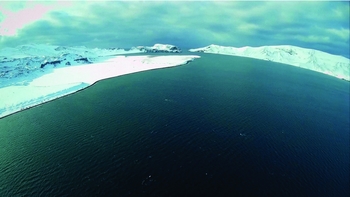
The quality of the recorded footage is very clear and would give the command team excellent situational awareness for the immediate area. It also provides an impressive view of the Deception Island crater, see Fig. 15.
Initial evaluation indicated that the aircraft airframe was again reusable, however, as per the previous flights, some of the avionics components were not.
Launch Five – 3 April 2016
10.15 Synopsis
Inconclusive flight in terms of operational requirement; but longest flight to date.
With the ship sailing north later in the day to meet a weather window, this was the last opportunity to fly. GPS coverage was less than usual but appeared to be sufficient. However, a sustained loss of GPS signal was experienced during flight that caused SULSA to navigate increasingly erratically, and manual control was taken when the aircraft was 700 – 800 m from the ship. Control was recovered and the rest of the flight was conducted in manual mode.
10.16 Background
The 5th flight was intended to be a repeat of a profile to survey a specific area requiring EVLOS flight. However, during launch preparations, the GCS displayed a GPS error. It was decided to swap aircraft to determine if this was a problem with the aircraft or GPS reception. On start-up of the other aircraft, the GPS error momentarily illuminated before clearing. It was decided to go ahead with the planned flight; however, since the ‘spare’ aircraft was being used, the alternate flight profile was used (this aircraft had been assembled using avionics recovered from a previous flight, and to mitigate any potential unforeseen problems with the autopilot, a profile was designed which would ensure that the aircraft would remain within a 900 m radius of the ship whereby the UAS operator could take control immediately. This would also mitigate any GPS problems encountered.
This was the last day that HMS Protector would remain in the Antarctic region and therefore the last opportunity to fly under 60° South within the existing Notice to Airmen (NOTAM).
10.17 Test conditions and results
The test flight intended to prove the reusability of the avionics package following a previous ditching.
The autopilot module was the only part of the avionics that required to be reused with the engine, camera, speed control unit and battery all replaced with new items. It was also intended that the flight would be used to gain footage of the ship in the Antarctic environment as the last opportunity in the Antarctic region – this was a requirement requested for university publicity reasons. As this was considered to be the ‘spare’ airframe, it was the only one not painted with highlighted colours (i.e. it was plain white), hence another reason to maintain a closer range. The flight was conducted using the template shown in Fig. 16.
A frame from the video captured during the third flight.

The route was planned using the reference method of plotting waypoints with particular effort to ensure correct orientation with the ship's head. The autopilot safety perimeter was set at 900 m (if route maintenance failure occurred and the UAV reached this range, the aircraft would automatically return to its ERP at G45 300 m where it would orbit until ditched).
The aircraft was launched into wind GREEN 90 in 2 – 3 kn negligible gusts. The launch was fault free and efficient. After attaining the initial cruise altitude of 200 ft (above flight deck), the UAV turned towards its first waypoint and conducted its planned two orbits before departing to WP 2. At some point during this transit the GCS operator reported that the UAV had registered a GPS failure with zero satellites. Approximately 30 seconds later, the GCS Operator reported that the UAV was diverging from the flight path by over 100 m with no attempt to correct. The UAV still (visually) appeared to be following its planned flight path in that it was orbiting at approximately the correct time scheduled. Around this time, the ship reported that the GPS position in dynamic positioning had also momentarily failed. Approximately 30 seconds later, the GCS Operator then reported that the UAV had crossed the safety radius at 900 m from HMS Protector (flight time approximately 4 minutes). The GCS Operator also reported that the aircraft flight path (as displayed on the GCS laptop) appeared highly erratic. As the aircraft was still visual (with aided visual support from the bridge), the UAS Operator took MANUAL control and flew the UAV directly back to the ship. As this was one of the last remaining flights, it was decided to get some camera footage of the ship before conducting a safe ditch in the sea approximately 30 m of the STBD quarter. The UAV was recovered safely to the ship.
Flight time was 14 mins 30 seconds. Approximately 13 minutes of footage was obtained from the camera. The flight track recorded by the aircraft GPS is shown in Fig. 17.
Launch five flight profile.

Launch five flight track. Note that this is based on the GPS positions logged by the autopilot and is not representative of the flight path followed by the aircraft in this case.

A frame from the video captured during the last flight.

10.18 Analysis
Once again, the UAV illustrated its excellent aerodynamic performance – flight was very stable and, under ASSISTED control, highly responsive and manoeuvrable.
The exact cause of GPS failure is unknown but is not thought to be a technical issue with the AV/GCS (i.e. functioning as designed), however, at this latitude, lack of GPS could simply be due to the ship's position and time of day where the coverage is not as great as previously encountered; this is corroborated by HMS Protector losing its GPS position at approximately the same time. The UAV GPS failure may also be due to incorrect almanac data or atmospheric model, however, lack of detailed technical knowledge of SULSA's GPS means that this cannot be checked.
This flight highlights the SULSA's reliance on GPS – once the GPS failed, (theoretically) the navigation of the UAV should have reverted to the on-board Inertial Reference System (IRS) with its compass at least providing a directional reference for the UAV to turn and head in the general direction of the ship. It is unknown why this did not occur; the IRS system itself did not fail as the UAV was correctly orientated throughout the flight and therefore it may be concluded that the AV's compass did not function correctly – due to lack of knowledge of the SULSA avionics systems, it cannot be definitively determined at this stage. There is also the possibility that any errors in the compass system (or any module of the avionics packages) may have been suspect due to previous damage incurred by salt water immersion.
The UAV failed to meet the requirements of the flight in that it was unable to adhere to the pre-planned route. If this had been a beyond line of sight, then it assessed that the aircraft control may have been unrecoverable.
Despite the majority of the flight being in ASSISTED control, the quality of the recorded footage is very clear and would give the command team excellent situational awareness for the over-flown area, see for example Fig. 18.
11.0 TRIAL RESULTS
11.1 Aircraft performance
Success Criteria: The aircraft demonstrates sufficient performance in the Antarctic environment to enable climb to the desired altitude and achieve the endurance of the planned flight (approximately 10 min).
Result: Aircraft performance was evaluated during ground testing prior to the initial flight to determine the maximum duration of the aircraft battery in the ambient temperature of the Antarctic region. Testing was conducted at 9° and 0° and with batteries cold soaked, held at ambient temperature and pre-warmed. The aircraft's battery protection circuit was set at its lowest value (although this safety feature was removed for test flights so that the battery could be used to depletion). Each trial run was commenced with 30 sec of full power throttle to simulate the launch setting. In all test cases, the performance assessed was the same, giving 13 min 5 sec with full power applied and 30 min with cruise power applied (approx. 55% of maximum throttle setting). During the flight test phase, the longest flight conducted was 14 min 30 sec at an operational temperature of 1°. The aircraft performance met the success criteria.
Analysis. It is assessed that although Lithium Polymer (LiPo) batteries are prone to degradation at low temperatures, the initial discharge rate of the battery combined with the enclosed airframe warmed the battery to its operating temperature which it maintained throughout the flight.
11.2 Aircraft launch
Success Criteria: The aircraft is able to clear the launcher and adopt the correct climb attitude to enable engine and aerodynamic performance to take over from ballistic launch performance.
Result: The launch system was evaluated during all SULSA launches. Launch criteria was: Ship in dynamic positioning with deck roll and pitch limits of +/–2°, wind 20 kn at Green 90, and gusts 3 – 4 kn. Following the loss of the first aircraft from an impact on deck, a number of modifications were made to the launcher system. All subsequent launches were conducted without incident. The aircraft launch performance met the success criteria.
Analysis. The first launch resulted in an impact with the deck approximately 3 m from the end of the launcher, assessed to be due to inadvertent movement of the aircraft on the launch cradle due to wind gust immediately prior to launch, combined with a weaker than expected launch force. Analysis determined that the aircraft velocity at the end of the launcher was 15 m/s compared to the required 20 m/s. The launcher bungee was replaced and tested using a test weight. Minor alterations were made to the cradle to prevent aircraft movement and the launcher platform raised by 1 m off the flight deck.
The launcher system is perhaps an over-engineered system designed to get a relatively light UAV sufficient forward inertia to allow flight. However, with the pusher propeller, it is not possible to simply hand launch the aircraft without risk of injury.
11.3 Post-launch climb-out
Success Criteria: Maintain a positive rate of climb and be able to achieve selected pre-planned altitude within a safe distance of the ship.
Result: The aircraft's post launch climb-out performance was evaluated on all successful launches with wind at Green 90 ranging from light airs to a maximum of 23 kn. In all cases, the aircraft exhibited a very stable platform with performance increasing with increasing wind speed. Establishment at the climb angle was evident with good lateral control to maintain a direct into-wind heading. The aircraft's post-launch climb-out performance met the success criteria.
11.4 Establish at selected altitude
Success Criteria: Aircraft establishes desired pre-planned flight altitude.
Result: The aircraft's ability to establish itself at any desired altitude was evaluated throughout the flight test phase. Approximation of flight altitude was conducted by reference to the ship's super-structure and by observing relative changes in altitude commanded by the autopilot and GCS. In all cases, the aircraft appeared to fly at the demanded altitude within approximately +/–20 ft. The aircraft's altitude performance met the success criteria.
Analysis: Without detailed telemetry from an on-board calibrated source, or from an external reference system, it is impossible to determine the exact performance of the aircraft pitot/static system. However, the observed performance was considered fit-for-purpose.
11.5 Establish flight path
Success Criteria: The aircraft establishes itself on pre-planned flight path (course/speed).
Result: The aircraft's ability to establish itself on a pre-defined flight plan was evaluated throughout the flight test phase using planned routes. In all flights, the aircraft reacted appropriately on the over-flight of the initial waypoint varying its course and airspeed appropriately. The aircraft's ability to establish itself on its pre-planned route met the success criteria.
Analysis: These criteria aimed to test the aircraft's ability to handover from its pre-programmed climb-out logic to the user defined route plan. In all cases, the handover was conducted without fault.
11.6 Flight path maintenance performance
Success Criteria: Aircraft is able to follow the pre-planned route accurately executing all turns at the desired point at the planned airspeed and altitude.
Result: The aircraft's flight path maintenance performance was evaluated throughout the flight test phase using routes of varying length and complexity. A number of issues were identified which prevented the aircraft from maintaining its route to within an acceptable error margin. The aircraft's flight path maintenance performance failed to meet the success criteria.
Analysis: Aircraft Dynamic Performance: During the first successful flight (launch two), a fairly tight route was devised in order to keep the UAV within VLOS of the ship in order to observe its behaviour. It was found that although the UAV would perform its pre-planned course alterations on the over-flight of waypoints, it was unable to perform adequate course corrections in sufficient time to become stable on each path leg length before the over-flight of the next waypoint. This led to increasingly inaccurate positioning and a divergence from the route to the extent that the UAS Operator had to take control prior to completion of the route. Physical evaluation of the control surfaces suggest that the FCS will have adequate control authority of the surfaces, and therefore, it is assessed that the autopilot FCS has not been optimised to implement adequate control laws that will allow the aircraft to quickly and efficiently acquire and maintain any specified course. It is worth also noting that although the steering law implementation seemed poor, the autopilot auto-stabilisation appeared to be excellent – the aircraft always seemed highly stable and correctly orientated throughout its speed and altitude envelope.
Discrepancy between ship and GCS GPS models: During subsequent flights when the EVLOS flight was conducted, the pre-planned route was designed such that the way points would allow sufficient time for the FCS to stabilise on the heading before requiring the aircraft to alter course again. Although this provided a much better route maintenance performance, it highlighted severe discrepancies between the ship's GPS system (WECDIS) and that employed by the SkyCircuits software on the GCS. The latitude/longitude of the survey area and the ship's location was provided and input to the GCS PLAN tool. It was immediately noticed that the range and bearing given between the survey area and the ship were significantly different on GCS and WECDIS. (GCS gave 1,325 yards at 223° whereas WECDIS gave 1,600 yards at 216°.). The Ship has assured WECDIS as the navigational authority for the area of operations, whereas it was not clear on what World Geodetic System (WGS) the SkyCircuits GCS has been based. Due to the discrepancy on WGS interpretations, the accuracy of the GPS was placed in doubt – while the GPS position derived from its receiver may be highly accurate, the autopilot's interpretation of it may lead to significant errors.
Loss of GPS: Notwithstanding the WGS discrepancies described previously, during the last flight, the GPS received signal failed soon after launch. On probability, it was assessed that this was principally due to time of day and relative position at a latitude greater than 60° South which seemed to be corroborated by the ship momentarily losing its GPS signal at the same time. On losing GPS, the UAV reverted to its IRS and magnetic compass to follow its route. The GCS Operator reported that the aircraft's position (via telemetry) was becoming increasingly inaccurate and erratic. The UAS Operator took control and returned the UAV to the ship rather than trust the automatic route following. Only access to additional satellites would seem to offer a solution to such issues.
11.7 Automatic over-flight of TWP
Success Criteria: Aircraft accurately over-flies TWP and enters into a holding pattern until ASSISTED or MANUAL control has been achieved.
Result: The aircraft's ability to return to its TWP was evaluated during all test flights. With the exception of flight launch four, the UAS operator was required to take control of the aircraft prior to the aircraft reaching the final waypoint and entering its holding orbit. The aircraft's ability to follow its pre-planned route to the TWP failed to meet the success criteria.
Analysis: The failure of the aircraft to reach the TWP is very much linked to the success criteria of the previous section. Launch four was the exception in that the aircraft adhered to the plan and arrived, as expected, at the TWP and entered its terminal orbit. Launch four was assessed as successful due to a balanced route geometry with fairly small heading alterations with long leg lengths to allow the aircraft to stabilise on each.
11.8 ‘Soft’ ditch in sea
Success Criteria: Once in ASSISTED or MANUAL control, the UAS Operator will control the flight of SULSA to a ‘soft’ landing on the sea, without the aircraft breaking apart.
Result: The aircraft's controllability to conduct a soft ditch in the sea within the immediate vicinity of the ship was evaluated at the end of every successful flight. The UAS Operator was able to easily take control of the UAV and smoothly fly it to an accurate and repeatable landing point. The ability to conduct a safe and effective ‘soft’ ditch in the sea met the success criteria.
Analysis: In MANUAL and ASSISTED control, SULSA is a highly agile and easily controllable aircraft. The UAS Operator had no difficulty in performing the ditching which resulted in no structural damage to the aircraft at all.
11.9 Utility of video media in conducting ice survey for navigation
Success Criteria: The memory card holds video media taken along the planned route of the aircraft and that then can be correlated to the ice in the vicinity of the ship (and hence be useful for navigation).
Result: The utility of video media was assessed following every flight. It was found that the method of aircraft recovery (by ditching) meant that recovery of the media was not reliable due to salt water ingress into the avionics (and camera unit). Regardless, the media was recovered with considerable high-quality, colour footage of the flight path which could easily be used for navigation. Combined with the pre-planned route, the footage could be easily correlated to the survey route; however, due to restrictions placed on the maximum range of the aircraft and test conditions at the time, the aircraft was not actually able to take footage of ice fields for assessment in conducting ice navigation. The utility of video media failed to meet the success criteria in that the test was inconclusive.
Analysis: The method of recovery is essentially unrealistic for an environment such as the Antarctic and detracted from the trial aims. For obtained footage to be useable, it must be timely and relevant; however, there is a significant effort required to launch and recover the ship's boat to retrieve the UAV from the sea, especially as this places the boat's crew at a higher level of risk in the extreme Antarctic environment. Similarly, when in proximity of ice, the ship's boat would not have been able to launch and hence the aircraft would not have been in the best position to provide ice navigation assistance out to the low range of 1.5 km.
Footage was not obtained for the full duration of all flights. It was found that the camera would not consistently survive the ditching in the sea and occasionally failed to record. Modifications were made to the method of operation which enabled periodic ‘clips’ to record to the on-board SD card; this allowed the majority of the flight to record with only the clip recording at the time of ditching lost due to camera failure.
The footage obtained was a direct recording which could only be relayed to the ship's command following recovery. The largest inadequacy of the system was that it did not provide a live Full Motion Video (FMV) downlink. Subsequent versions of SULSA will provide a suitable link.
11.10 Re-usability of aircraft
Success Criteria: Once recovered from the sea, the aircraft can be refurbished within the ship for further flights.
Result: The reusability of the SULSA aircraft following a soft ditch in the sea was evaluated following every successful flight. In all cases where a soft ditch was conducted, the airframe received no structural damage and was assessed airworthy for subsequent flights. However, all avionics were subjected to a higher degree of assessment. All servos were found to be largely unaffected by the landing and, following cleaning and function testing, were deemed as serviceable for flight. Similarly, one autopilot module was assessed as serviceable and was re-flown on the last flight. However, the camera unit, the speed control unit, power interface and battery were all deemed un-fit for further flight. The aircraft's ability to be re-used following a soft ditch in the sea met the success criteria.
Analysis: While it was proved that the majority of the aircraft could be reused, due to the various failure modes associated with salt water ingress, it does not provide a consistent result.
The requirement to ditch in the sea was a provision made to ensure the meeting of immediate health and safety concerns. However, given the low landing speed and controllability of the aircraft, it would be feasible for the aircraft to have been landing on the flight deck near the stall speed and captured by the flight deck nets (or similar restraining net). This would have increased the usability of the media by reducing the time to relay media to the bridge, reduced any risk to the boat's crew and enabled flight in ice fields. The only risk would have been to those on the flight deck; however, this is assessed as not being any higher than exposure to the aircraft when flying from land.
12.0 CONCLUSIONS
This series of flight trials has established that very low-cost fixed wing UAVs can be successfully operated and recovered at sea, including in low-temperature environments, and high-quality video footage can be obtained either for operational or scientific purposes. In general, SULSA met the requirements of the trial objectives set at the outset of the project. While this aircraft would be deemed not immediately fit for Antarctic naval operations, it has been extremely beneficial in investigating and developing the requirements for an aircraft bespoke to the unique nature of the Antarctic environment and HMS Protector's role. Sea landings do not appear to significantly stress the airframe over and above the normal levels encountered in grass strip based operations. Further refinements to the waterproofing of internal avionics would increase the reusability of some components, although some items such as motors, which of necessity require air-cooling, probably have to be regarded as sacrificial elements. Although sea boat recovery imposes operational restrictions on the ship's command, the low cost of the systems being used would allow airframes to be abandoned if absolutely required. However, such a recovery mode is probably not best suited to Arctic or Antarctic waters where sea boat operations can be hazardous and where environmental concerns mean that being unable to recover aircraft would not be acceptable – in such circumstances, net based recovery on the flight deck would probably be preferable. The addition of a real-time video link would significantly increase the operational utility of the system but would increase the airframe cost if miniaturised high-bandwidth long-range transmitters were required.
ACKNOWLEDGEMENTS
Our particular thanks to the Commanding Officer of HMS Protector, R. J. L. Bryan OBE, Capt RN and his crew, who made this series of flight trials possible. Their unstinting support is gratefully acknowledged.