Introduction
Nanoporous metallic foams (MF) made of materials such as gold (Au), copper (Cu), platinum (Pt), and nickel (Ni) exhibit several remarkable properties associated with their low relative density and high specific surface area, such as high strength-to-weight ratios, and enhanced catalytic and plasmonic behavior. These properties can lead to a number of potential applications in areas such as dye-sensitized solar cells [Reference Xue, Liu, Chen, Wang, Li, Qu and Dai1], catalyst materials [Reference Bhaviripudi, Mile, Steiner, Zare, Dresselhaus, Belcher and Kong2, Reference Patel, Li, Wang, Zhang and Wei3], fuel cells [Reference Corbin, Clemmer and Yang4, Reference Tseng, Heush, Chiang, Lee and Lee5], hydrogen storage foams [Reference Shinde and Tayade6, Reference Mellouli, Dhaou, Askri, Jemni and Ben Nasrallah7], and plasmonics [Reference Biener, Nyce, Hodge, Biener, Hamza and Maier8]. However, nanoporous MF suffer from macroscopically brittle behavior due to plastic deformation in individual nanowires [Reference Biener, Hodge and Hamza9], which is a limiting factor for their applicability.
Nanoporous MF is a cellular structure consisting of a large number of connected nanowires in a 3D network. Therefore, the mechanical behavior of a nanoporous MF is determined by the relationship between the behavior of the individual nanowires that make the foam and their geometry. More specifically, the macroscopic strength of a MF cannot exceed the strength of the individual nanowire it is made of. Hence, to construct stronger MF, the strength of the individual nanowires must be increased. But unfortunately, it is almost impossible to improve the strength of the metal nanowires, especially at the nanoscale level, since the dealloying techniques that are conventionally used to manufacture nanoscale MF do not allow strengthening agents such as precipitations, solid solutions, and nanograins. Therefore, a different strengthening approach must be used.
Nanoscale metallic multilayers (NMM) are a unique class of nanoscale composite materials consisting of thin planar alternating metallic films within nanoscale dimensions [Reference Zhou, Xie, Wang, Huang, Xu and Lu10, Reference Mastorakos, Zbib and Bahr11, Reference Hoagland, Kurtz and Henager12, Reference Abdolrahim, Zbib and Bahr13]. NMM structures can be fabricated by vapor deposition or electrodeposition of two or more metals in an alternating manner [Reference Misra, Verdier, Lu, Kung, Mitchell, Nastasi and Embury14]. They have already shown their potential as they exhibit ultra-high strength compared with each bulk constituent. Mastorakos and his co-authors have investigated that thin planar films made of alternating nanoscale layers (Cu–Ni) show remarkable mechanical properties as well as evidence of strain hardening [Reference Mastorakos, Zbib and Bahr11, Reference Mastorakos, Abdolrahim and Zbib15]. It is the interface between different materials that causes the strengthening effect of the NMM structure. There are three major types of interfaces in NMM systems depending on different constituents of the multilayers: coherent, semi-coherent, and incoherent. Coherent interfaces are made of metals with the same type of lattice structures (e.g., FCC on FCC or BCC on BCC) with a small lattice mismatch that suppresses the formation of misfit dislocations on the interface [Reference Hoagland, Mitchell, Hirth and Kung16, Reference Shao and Medyanik17]. Semi-coherent interfaces have again the same type of lattice structure, but a significantly larger lattice mismatch than the coherent type that allows the formation of misfit dislocations [Reference Mitlin, Misra, Mitchell, Hirth and Hoagland18, Reference Shao and Wang19]. Finally, incoherent interfaces are made of metals with different types of lattice structures, such as FCC on BCC [Reference Wang, Hoagland, Hirth and Misra20, Reference Hoagland, Hirth and Misra21]. The mechanical behavior of the NMM structures depends on the type of the interfaces contained within each system. For our current study, since the three metals (Cu, Au, and Ni) we considered here in our paper are all FCC types, only the coherent and semi-coherent interfaces have been considered.
As a result, our hypothesis is that we can form stronger individual nanowires by coating them with NMM structures, thus making composite nanowires. Previous studies on core–shell structured nanowires such as Cu–Ni [Reference Abdolrahim, Mastorakos and Zbib22], Cu–Ag [Reference Li, Yang, Luo, Jin, Liu and Gao23], Au–Ag [Reference Sun, Xu, Wang, Gu and Feng24], and Au–Ni [Reference Abdolrahim, Bahr, Revard, Reilly, Ye, Balk and Zbib25] have demonstrated their ability to increase the overall strength by adding a thin layer of coating. Thus, it is possible to increase the strength of a nanoporous MF by coating its individual nanowires with NMM structures, thus developing a composite MF. However, these studies have only studied the effect of very thin coatings, and they did not explore the effect of a thicker coating on the strengthening of the nanowires, nor they compare various types of interfaces. In this work, we investigate the mechanical response of the bimetallic nanowires during uniaxial loading at varying shell thicknesses and two types of interfaces.
In this view, the purpose of the current study is to investigate the mechanical response and the associated deformation mechanisms of pure metallic nanowires, compare them to their composite bimetallic counterparts with two types of interfaces, and explore whether there exists a critical shell thickness that produces the optimum strength. The structure of the paper is as follows: In section “Methodology,” our methodology and the geometries we used are outlined. In section “Results and discussion,” the molecular dynamics (MD) simulation results are presented and the deformation mechanisms are analyzed and discussed. Finally, in section “Conclusions,” the conclusions of this work are presented.
Results and discussion
Uniaxial tensile test
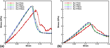
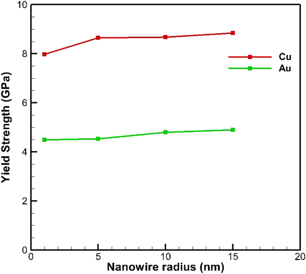
First, pure Cu and Au nanowires with different radii are uniaxial loaded. Typical snapshots of some atomistic configurations at different stages of the uniaxial loading process are shown in Fig. S1. The resulting stress–strain curves for the pure metal nanowires from the MD simulations are shown in Fig. 1, and the yield strengths are listed in Table SI. The yield strengths of pure Cu and Au are around 8.5 GPa and 4.5 GPa, respectively. Overall, simulation results show that pure Cu nanowires are stronger than pure Au nanowires, following the same trend as in their bulk materials. The yield strengths of pure metal nanowires with different radii are compared in Fig. 2. From the figure, we can see clearly that the yield strength of both pure metallic nanowires slightly increases with the radius of the nanowire. This “smaller is softer” effect is in agreement with those reported in Au nanowires [Reference Marian and Knap41, Reference Gan and Chen42]. As a result, the surface energy is the main factor that determines this effect. The surface energy increases with the increase in size in small nanowires, which causes the increase in the yield strength. Moreover, previous studies [Reference Misra and Hoagland43, Reference Misra, Hirth and Hoagland44] on yield strength of nanolaminate structures with individual layer thicknesses comparable to the radii of our nanowires also indicate that these thicknesses are typically at the softening region of the strength versus the thickness plot. Although the structures studied in [Reference Misra and Hoagland43, Reference Misra, Hirth and Hoagland44] are not the same, the reason of the behavior is attributed to the small layer thickness rather than the composition and thus the same must apply in our case as well.
Stress–strain curves from simulated uniaxial tensile behavior of pure metallic nanowires. (a) and (b) are corresponding to Cu and Au nanowires, respectively.

Comparison of the uniaxial loading yield strength of pure Cu and Au nanowires with different radii.

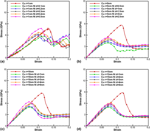
Then, Cu/Ni composite nanowires have been simulated. The semi-coherent interface between Cu and Ni has been formed by adding a second shell layer on the previous core nanowire and relaxing the structure. Snapshots of some atomistic configurations at different stages of the uniaxial loading process are shown in Fig. S2. The resulting stress–strain curves are shown in Fig. 3, and the yield strengths are listed in Table SII. The results clearly demonstrate that the addition of the Ni layer on the Cu nanowire does not strengthen the nanowire (compared to its simple metal counterpart), even when the ratio of the shell thickness to core radius is as large as 0.5. This indicates that it is not possible to strengthen a Cu nanowire by simply forming a semi-coherent interface with Ni.
Stress–strain curves from simulated uniaxial tensile behavior of semi-coherent Cu–Ni bimetallic nanowires. Those composite nanowires are compared with the pure metal nanowires to investigate their mechanical behavior. The core radii of nanowires are 1 nm, 5 nm, 10 nm, and 15 nm, corresponding to (a), (b), (c), and (d).

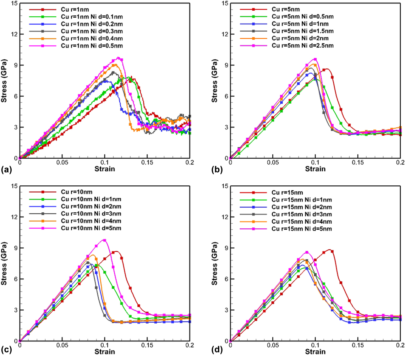
Also, the coherent interface between Cu and Ni has been considered. In general, even for layers with small misfit, a semi-coherent interface is more likely at large layer thicknesses. However, for thin layers, a coherent layer is possible [Reference Hoagland, Mitchell, Hirth and Kung16]. In our case of Cu/Ni, and the thin layers we consider, fully coherent interfaces between Cu/Ni are more favored energetically [Reference Hirth and Feng45]. The lattice parameter of Cu is 0.3615 nm and the lattice parameter of Ni is 0.352 nm, which results in a small misfit of about 2.7%. We used the method provided by Hoagland [Reference Hoagland, Kurtz and Henager12] to calculate the corresponding lattice parameter after the nickel layer has been stretched and copper compressed, which is 0.3556 nm. Snapshots of some atomistic configurations at different stages of the uniaxial loading process are shown in Fig. S3. The resulting stress–strain curves are compared in Fig. 4, and the yield strengths are listed in Table SIII. As shown in Fig. 4, the coherent Cu–Ni nanowires show similar trend for all nanowires with the same core radius; namely, the overall strength increases with the increment of the shell layer thickness. Compared with the semi-coherent cases between Cu and Ni, the coherent cases show improved strength overall although the strengthening effect decreases when the core radius increases. Also, the strengthening effect does not show any considerable size dependence; for example, it exists even when the core radius is 1 nm.
Stress–strain curves from simulated uniaxial tensile behavior of coherent Cu–Ni bimetallic nanowires. Those composite nanowires are compared with the pure metal nanowires to investigate their mechanical behavior. The core radii of nanowires are 1 nm, 5 nm, 10 nm, and 15 nm, corresponding to (a), (b), (c), and (d).

Last, the effect of a Ni layer around the Au layer has been considered. The lattice parameter of Au is 0.408 nm and the lattice parameter of Ni is 0.352 nm, which results in a lattice misfit of 13.7%. Initially, the structure was formed assuming a coherent interface, following the guidelines found in [Reference Hoagland, Kurtz and Henager12]. However, during the energy minimization and relaxation process, the large mismatch resulted in a loss of coherency with a number of misfit dislocations forming in both sides of the interface. It is impossible to form a coherent case with Au and Ni; hence, only a semi-coherent interface is considered.
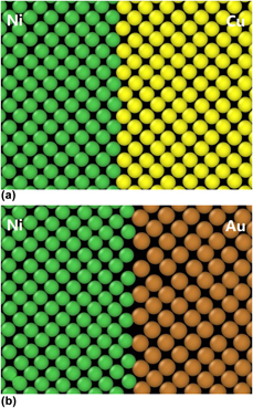
Here, a comparison of coherent copper–nickel interface and the semi-coherent gold–nickel interface is shown in Fig. 5. In this figure, one layer of the atoms is shown to compare the coherent and semi-coherent interfaces. We can see clearly that in the interface of coherent case, the atoms still remain in their own place in the lattice. However, in the semi-coherent case, the Au atoms in the Au/Ni interface changed from their original lattice, while the Au atoms away from the interface still sit in their own sites.
Comparison of the coherent interface between Ni and Cu (a) and the semi-coherent interface between Ni and Au (b).

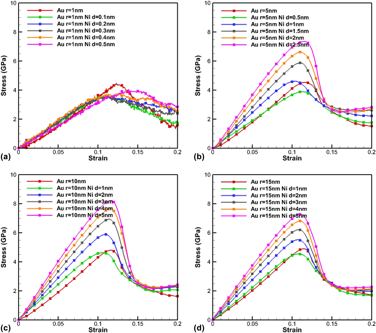
Snapshots of some atomistic configurations at different stages of the uniaxial loading process are shown in Fig. S4. The resulting stress–strain curves are shown in Fig. 6, and the yield strengths are listed in Table SIV. For the 1-nm case, the addition of a Ni layer on the Au nanowire does not show strengthening effects even when the ratio of the shell thickness to core radius is as large as 0.5. This indicates that it is not possible to strengthen the very thin Au nanowires simply by adding a second shell layer. However, the situation is different for the thicker cases. As shown in Fig. 6, the addition of the nickel layer in core–shell composite nanowires increases the yield stress of the structure. Overall, the strengthening effect was shown to be significant for a thicker shell (shell thickness/core radius ratio above 0.2), where the addition of Ni improved the overall strength of the Au wires.
Stress–strain curves from simulated uniaxial tensile behavior of Au–Ni bimetallic nanowires. Those composite nanowires are compared with the pure metal nanowires to investigate their mechanical behavior. The core radii of nanowires are 1 nm, 5 nm, 10 nm, and 15 nm, corresponding to (a), (b), (c), and (d).

Comparison of results
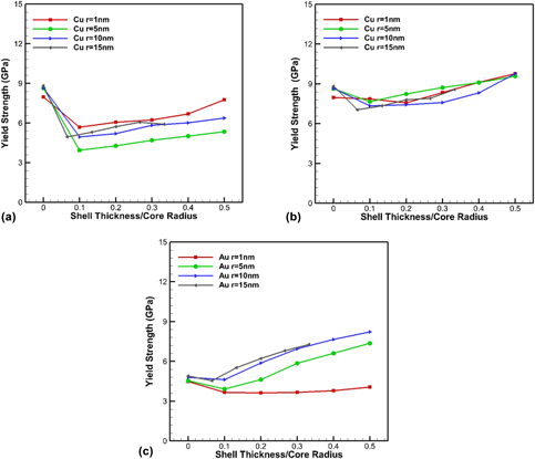
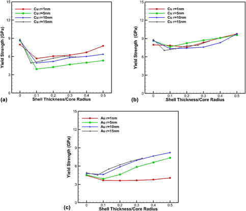
As shown in Fig. 7, the yield strengths of the structures were compared with respect to their shell thickness over core radius ratios. It is concluded that the overall strengthening effect of the shell Ni layer is more pronounced in Au nanowires than in Cu nanowires, although the composite Cu/Ni nanowires are much stronger. For the semi-coherent Cu/Ni nanowires, all the coated nanowires do not show any strengthening behavior compared with the pure Cu nanowires. For the coherent Cu/Ni nanowires, the yield strengths of the composite nanowires increase with the shell thickness ratios, as they could be considered as a “new” metal with a different lattice constant; hence, their mechanical behaviors are similar. In order to compare the strengthening effects of composite nanowires, we define the concept of critical thickness, which means if the shell thickness has exceeded the critical thickness, the yield strength of the composite nanowire is higher than the pure nanowire. The critical thickness of the Ni shell layer is around 0.4 of the Cu core radius. For the semi-coherent Au/Ni nanowires, when the Au core radius is 1 nm and the Ni shell layer is from 0.1 to 0.5 nm, there is barely one layer of Ni atoms outside the Au layer. Composite structures of FCC/FCC type with a very thin layer exhibit a softening due to the leakage of dislocations between the interfaces [Reference Mastorakos, Bellou, Bahr and Zbib46]. When the Au core radius is of the range 5–15 nm, the added Ni layer has enough thickness, so the overall strength is increased. The critical thickness of the Ni shell layer is around 0.1 of the Au core radius. A more detailed explanation is presented in section “Results analysis.”
Plots of yield strength versus the ratio of shell thickness to core radius. The Cu–Ni nanowires are shown in (a) for the semi-coherent interface and (b) for the coherent interface, and the Cu–Ni nanowires are shown in (c). Note that shell thickness/core radius ratio is zero means that there is no shell layer added, which means these are pure Cu nanowires in (a) and (b) and pure Au nanowires in (c).

For all simulations, dislocation-free specimens have been considered. Chu et al. [Reference Chu, Wang, Zhou and Beyerlein47] also investigated specimens with preexisting dislocations and found that the presence of dislocations can lower the mechanical strength of nanowires with core–shell structures. In our case, the flow stress can give us an indication of the deformation of dislocation-rich nanowires. More specifically, when loading a nanowire with preexisting dislocations, its yield stress will correspond to (or be very close to) the flow stress of the same nanowire with no dislocations inside. The reason is that the flow stress represents the stress needed for the dislocations to propagate rather than nucleate. In this view, the flow stresses shown in Figs. 3, 4, and 6 show similar trends with their corresponding yield stresses, indicating that the yield strength of preexisting nanowires follows similar trends as well.
Results analysis
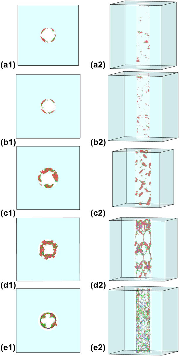
To study the dislocation nucleation and propagation within the structure and to explain the observed behaviors, we compared the two sets of cases of Cu/Cu–Ni and Au/Au–Ni nanowires. The radius for pure Cu and Au is 5 nm, the core radius for the composite Cu/Ni and Au/Ni is 5 nm, and the shell thickness is 1.5 nm. The results are shown in Fig. 8.
Snapshots of pure Cu (a) and Au (b), and composite coherent Cu/Ni (c) and semi-coherent Cu/Ni (d) and Au/Ni (e) nanowires at the stage of yield point. The top views and front views are shown correspondingly.

These figures show the deformed nanowires just after the yield point for pure Cu and Au, and Cu/Ni and Au/Ni, respectively. We can clearly see the difference from the top views between the first three cases (pure Cu, pure Au, and coherent Cu/Ni) and the last two semi-coherent Cu/Ni and Au/Ni cases. In the first three cases, the first dislocation emerged from the free surface, while in the last two cases, it is the interface between Au/Ni that actually acts as the nucleation place for dislocations to propagate.
For the coherent Cu/Ni case, the small lattice mismatch between two metal layers results in a tensile behavior that is very similar to that of the pure metal nanowires of Cu and Au, where the first dislocations start from the free surface. Since it is the coherent interface, the Cu core layer is under compression while the Ni shell layer is under tension, which might explain why the first dislocations actually start from the Ni layer. Since Ni is the strong metal compared with Cu, this might also explain why the strengthening effect is not pronounced.
For the semi-coherent Cu/Ni case, the dislocations start propagating from the interface and move inside the copper layer. The presence of these misfit dislocations in the interface is the reason why the overall strengths decreased compared to pure Cu nanowires.
For the semi-coherent Au/Ni case, the dislocations first nucleate from the interface into the Au core layer and then into the Ni shell layer. The reason for this behavior is that the number of the dislocations absorbed by the free surface is now balanced by the number of dislocations that are trapped in the Au–Ni interface, for which a higher stress is required to overcome the obstacle. In other words, the interface acts as a barrier to the dislocations’ transmission from the Au into the shell Ni layer, which is the reason for the strengthening effect of the shell Ni layer.
A previous study performed by Misra [Reference Misra and Krug48] pointed out that the interface barrier strength is decided by the stress field of the misfit dislocations at the interface and the Koehler image forces on the dislocations. Compared to Cu/Ni, Au/Ni has a larger shear modulus mismatch between layers; the dislocations in the Au layer have to overcome a bigger repulsive image stress from the Ni layer before slip can be transmitted across the layers. This could be the reason why the strengthening effect on the Au nanowire is more pronounced than on the Cu nanowire.
Finally, the nanowires as parts of a nanofoam experience complex loading conditions and not only tension as in this work. However, the observed trends for the effect of the second layer on the strength of the nanowires should be similar for other loading conditions.
Conclusions
The strengthening of the nanoscale metallic nanowires by building the core–shell structure has been demonstrated. Both the semi-coherent interface of Au/Ni and Cu/Ni and the coherent interface of Cu/Ni have been simulated and compared. Overall, the Cu/Ni nanowires are stronger than the Au/Ni nanowires, while the strengthening effect of the shell Ni layer onto the Au core is higher than that onto the Cu core. The shell layers onto the Cu cores will make the nanowires stronger if they form the coherent interface and the shell layers’ thickness to core radius ratio exceeds the critical value of around 0.4. In the case of Au nanowire, the addition of the shell layer will show a strengthening effect when the core radius is larger than 5 nm and the shell layer is thick enough. Finally, the mechanisms of the mechanical behavior have been investigated. For the semi-coherent Cu/Ni nanowires, no strengthening effect compared to pure Cu nanowires has been observed. For the coherent Cu/Ni nanowires, the strengthening effect is present, although not too noticeable because the stronger metal (Ni) is already under tension and hence the overall strength does not improve much. However, in the case of the semi-coherent Au/Ni nanowires, the strengthening effect of the shell layer is significant. This is attributed to the obstacle that the semi-coherent interface presents to dislocation propagation, as it acts as a barrier to the dislocations’ transmission.
Methodology
MD simulations were performed using LAMMPS [Reference Plimpton26] with potentials based on the embedded atom method (EAM) [Reference Daw and Baskes27, Reference Daw, Foiles and Baskes28]. The EAM potentials used to describe the atomic interactions between Cu/Ni and Au/Ni are of the types given by Voter and Chen [Reference Voter and Chen29], Zhou et al. [Reference Zhou, Johnson and Wadley30], and Ward et al. [Reference Ward, Agrawal, Flores and Windl31]. These potentials have already shown great performance in dealing with interfaces, vacancies, and stacking fault energies in the past few years [Reference Mastorakos, Zbib and Bahr11, Reference Hoagland, Mitchell, Hirth and Kung16, Reference Wang, Hoagland, Hirth and Misra20, Reference Zimmerman, Gao and Abraham32, Reference Davoodi, Dadashi and Yarifard33, Reference Divi and Chatterjee34, Reference Zientarski and Chocyk35].
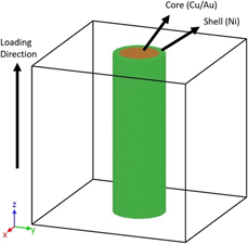
Since single nanowire is the basic component of the metallic nanofoam, we consider its mechanical behavior first to model the metallic nanofoam. In our paper, cylindrical nanowires with Cu or Au as the core and Ni as the shell were simulated. A representative geometry of the modeled nanowires with the loading direction is shown in Fig. 9. To model infinitely long nanowires, periodic boundary conditions were applied along the z-direction, which is also the uniaxial loading direction in all our simulations. All the structures used for the simulations have been created using Atomsk [Reference Hirel36], with the orientations of both core and shell layers being 〈100〉, 〈010〉, and 〈001〉 for x, y, and z, respectively. All nanowires were cylindrical with a length-to-radius ratio of 10.
Initial configuration for pure copper or gold nanowires (if shell layer is not added) and composite nanowires. The brown atoms are copper or gold, and the green atoms are nickel.

In all simulations, the temperature was kept constant at 300 K during both the relaxation and uniaxial loading steps. The isothermal–isobaric (NPT) ensemble was used to update the atomic velocities and positions at each step. The structures were subjected to a tensile loading of a constant strain rate of 5 × 10⁹ s−1. Initially, pure metallic nanowires made of Cu and Au of radii of 1, 5, 10, and 15 nm were considered. Then, Cu–Ni, and Au–Ni core–shell nanowires were tested to compare the effects of the Ni shell layer thickness on both Cu and Au wires. To study the effect of dislocation nucleation and propagation on the deformation mechanisms, the common neighbor analysis (CNA) [Reference Honeycutt and Andersen37, Reference Faken and Jónsson38] and dislocation analysis (DXA) [Reference Stukowski, Bulatov and Arsenlis39] techniques available in OVITO [Reference Stukowski40] were used.
Supplementary material
To view supplementary material for this article, please visit https://doi.org/10.1557/jmr.2018.491.
Acknowledgments
This work was supported by the National Science Foundation under Grant No. CMMI-1634640.