Introduction
In the present scenario in the field of technology, polarization plays a vital role in the proper functioning of communication systems because it allows the reception of signals irrespective of the alignment of the transmitting antennas. The attractive features of circularly polarized (CP) antennas, which includes their ability to overcome multi-path interferences and reduce the effect of Faraday rotation, make them very desirable in wireless communication systems. Several ways have been explored by various researchers to design a low-profile, cheap, and highly compact CP antenna; these methods include using a substrate of a high-dielectric constant [Reference Kan and Waterhouse1, Reference Lam, Luk, Lee, Wong and Ng2], implementing slots [Reference Patil, Singh, Kanaujia and Yadava3, Reference Singh, Patil, Kanaujia and Pandey4] and slits [Reference Nasimuddin, Qing and Chen5, Reference Patil, Singh, Kanaujia and Yadava6] on the patch, employing the ground plane with defective ground structures [Reference Singh, Gangwar and Kanaujia7, Reference Thakur and Par8], implementing reactive impedance surfaces (RISs) [Reference Agarwal and Nasimuddin9], using split-ring resonators [Reference Zarrabi, Mansouri, Ahmadian, Rahimi and Kuhestani10], complementary split-ring resonators [Reference Dong, Toyao and Itoh11], etc. Although the aforementioned methods led to the miniaturization of the antenna, they also degraded the antenna performance due to the presence of surface wave propagation in the substrate of the antenna. To overcome the stated drawbacks, researchers proposed electromagnetic band gap (EBG) structures which are periodic/aperiodic metallic/dielectric structures that prohibit the surface waves from traveling in the substrate of the antenna by introducing a specified stop band, thus leading to an improved performance of the antenna. Many researchers have implemented such structures on the antenna's ground surface [Reference Pflaum, Philippe, Kossiavas and Robert12], on its substrate [Reference Sudha and Vedavathy13], by surrounding it around the patch [Reference Rahman and Stuchly14], and also by using it as metasurface [Reference Zhu, Chung, Sun, Cheung and Yuk15] and, thus, recuperated the antenna's performance. In [Reference Yang and Rahmat-Samii16], mushroom-shaped EBG structures were implemented on the ground plane and, by utilizing its polarization-dependent in-phase reflection property with a dipole antenna placed above it, was able to generate CP waves at 3.56 GHz with an improved performance but with the limitation of a large ground plane of size 100 mm × 100 mm. In [Reference Xiulong, Ruvio and Ammann17], the performance of the CP antenna was improved by using an array of annular ring EBGs on the ground plane. Also, it achieved 10% reduction in the center frequency when compared to the antenna without EBG. Even though the structure proposed above showed an immense enhancement in terms of gain and efficiency, it still lacked compactness in terms of its physical dimensions. In [Reference Ahmed, Shaalan and Awadalla18], the CP waves were obtained using three N slots on the patch antenna and, later, on circular air hole as EBG structures were drilled on the substrate to enhance its performance and also to achieve compactness. However, it resulted in a complex fabrication process. In [Reference Encheng and Liu19], a compact CP antenna at 1.57 GHz was presented by printing fractal EBG on the substrate of the antenna which is made from organic material. Nevertheless, the aforementioned proposed structure showed a small axial ratio (AR) bandwidth of 31 MHz. In [Reference Wang, Zhang, Hong, Luo and Guo20], a slot-loaded slot antenna with mushroom-shaped EBG cells around it was able to generate CP waves with wide AR bandwidth. In [Reference Da Silva, De Siqueira Campos and De Andrade21], CP radiation was generated with enhanced gain and CP bandwidth by placing an EBG array as a polarizer above a patch antenna. In [Reference Qi, Guo, Vandenbosch and Ding22], a CP array antenna was proposed by utilizing the polarization conversion property of EBG. Although this antenna achieved wide AR bandwidth and radar cross-section reduction, it eventually lacked miniaturization. In [Reference Verma, Singh, Srivastava, Patil and Kanaujia23], polarization-dependent EBG structures were constructed to surround a rotated truncated patch in an attempt to design a CP antenna that would obtain an AR bandwidth of 50 MHz and a return loss bandwidth of 120 GHz. However, this led to an increase of the overall size of the antenna. In [Reference Verma, Singh, Srivastava, Patil and Kanaujia24], a high-gain compact CP slot antenna at 5.1 GHz was proposed with hexagonal ring-shaped EBG on the substrate with an impedance bandwidth of 18%. Recently, EBGs have been implemented as metasurfaces [Reference Wu, Li, Li and Chen25, Reference Sihao, Deqiang and Jin26] to enhance the performance of CP antennas. In [Reference Zhipeng, Ouyang and Yang27], a metasurface with a 4 × 4 square patch was designed to obtain a low-profile CP antenna. Although it achieved wide AR bandwidth, it achieved a narrow impedance bandwidth of 17%. A CP antenna, implemented with square-based metasurface, was proposed in [Reference Hussain and Parka28]. It had a multiple-slit feeding structure and was able to achieve 17.3% of 3-dB gain bandwidth but faced complexity in fabrication. In [Reference Verma, Singh, Srivastava, Patil and Kanaujia29], a coplanar waveguide (CPW)-fed CP antenna which had an inclined slot in the ground surface and was loaded with an EBG-based metasurface showed improved performance but lacked compactness. In [Reference Soumik and Dey30], an EBG array was implemented as a partially reflective surface above a metamaterial CP antenna to enhance its directivity but led to an increase in the physical size of the antenna. In [Reference Zeppettella and Ali31], a broadband spiral CP antenna was designed using planar EBG. It achieved a wide AR bandwidth by lengthening the concentric-shaped EBG patches but led to the lowering of gain at a high-frequency range. Thus, the above reported EBG-based CP antennas either lacked compactness or were not able to show wide return loss bandwidth or axial ratio bandwidth. With the aim of achieving a CP antenna and to show improvement in terms of impedance bandwidth and AR bandwidth along with miniaturization in size, in this paper, we have proposed a CPW-fed patch antenna with modified ground plane and six ellipse-shaped EBGs on the bottom side of the substrate to achieve miniaturization as well to report wide impedance and AR bandwidth. The proposed antenna is applicable for radio altimeter and wireless avionics infra-communication (WAIC) systems.
Proposed antenna configuration and ellipse-shaped electromagnetic band gap (EEBG) design
Design and evolution stages of proposed antenna
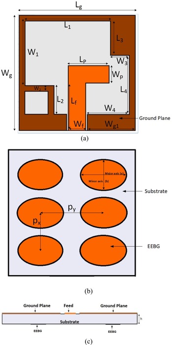
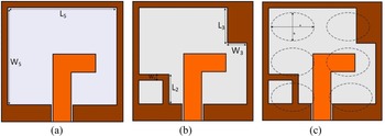
Figure 1 depicts the proposed antenna which comprises the patch with CPW feed built on an FR-4 substrate of thickness h and having a dielectric constant of 4.4. The ground plane has dimensions of Lg × Wg, is modified with rectangular slots and inverted L slit, and the substrate is etched with six EEBG structures at its bottom. Table 1 depicts the optimized parameters of the proposed structure. The suggested antenna is able to generate a wide impedance bandwidth with improved axial ratio bandwidth and gain by implementing the EEBG on its substrate. The three steps in which the design of the proposed antenna evolved are shown in Fig. 2. Step 2(a) illustrates a CPW-fed patch antenna (antenna A) with a rectangular slot of dimensions Ls = 18 mm and Ws = 16.2 mm. Figure 3 depicts the S 11 response of antenna A, which illustrates that an impedance bandwidth of 26.9% (4.05–5.31 GHz) is obtained when linearly polarized waves are generated, as shown in Fig. 4. Moreover, as depicted in Fig. 5, the peak gain of antenna A is 0.18 dBic in the operating bandwidth and is negative in the higher frequency range. To improve the impedance bandwidth and gain, the ground plane is further modified with a rectangular slit (L 3 × W 3) on the top right corner and inverted L-shaped slit of length L 2 and width W 2 are placed on the bottom right side of the ground plane. As shown in Fig. 3, the impedance bandwidth increases to 31% (3.90–5.33 GHz) and, as depicted in Fig. 5, the gain improves to 1.2 dBic. It is also observed from Fig. 4 that no CP waves are present. For the generation of CP waves, the dimensions of EEBG unit cell and the periodicity in the x and y axes are adjusted such that the impedance along the two diagonal directions vary, causing the induced current to change and results in the two orthogonal components to change as well. Thus, by optimizing the parameters of EEBG, when the condition |Z 1| = |Z 2| and ang(Z 1 − Z 2) = ±90° is achieved, the CP radiation is obtained. Therefore, it is observed from Fig. 4 that antennas A and B were unable to obtain CP radiation but, by implementing six EEBGs on the bottom of the substrate, antenna C resulted in 3 dB AR bandwidth of 8.53% (4.15–4.52 GHz) due to the generation of two orthogonal modes with a phase of 90°. It is also depicted from Fig. 3 that antenna C shows an improvement in impedance bandwidth of 33.33% (3.95–5.53 GHz) from 31% (3.90–5.33 GHz) of antenna B. Furthermore, due to additional inductance and capacitance introduced because of the elliptical-shaped EBG, there is a shift in the impedance bandwidth toward the lower frequency region. As depicted in Fig. 5, the EEBG inhibits the propagation of surface waves resulting in the gain of antenna C to enhance the peak gain to 3.13 dBic in the operating bandwidth (Table 2).
Proposed antenna: (a) top view, (b) bottom view, and (c) side view.

Evolution steps of proposed antenna: (a) antenna A, (b) antenna B, and (c) antenna C (proposed antenna).

Simulated S 11 varying with frequency of antennas A, B, and C.

Simulated axial ratio varying with frequency of antennas A, B, and C.

Simulated Gain varying with frequency of antenna A, B and C.

Parameters of the proposed antenna

Parameters of different design configurations

EEBG unit cell design
An EEBG which consists of six ellipse-shaped metal plates, arranged in the 3 × 2 layout with periodicity in the x and y directions as px and py, respectively, is proposed. It is placed on the antenna's bottom surface of the substrate, which is made of FR4 having thickness h. The elliptical EBG axes comprising of minor axis and major axis are situated at a = 4.8 mm in the x direction and with b = 7.2 mm in the y direction, respectively. Table 3 lists the optimized dimensions of the EEBG.
Optimized dimensions of EEBG

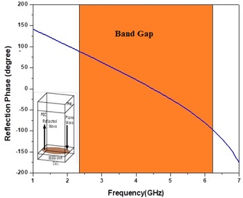
Using Ansoft's High Frequency Simulator Software (HFSS) version 15, the unit cell of the proposed EEBG is simulated and its in-phase reflection properties [Reference Samineni and De Khan32] are analyzed by implementing the Floquet-port model [Reference Sievenpiper, Zhang, Broas, Alexopolous and Yablonovitch33]. It is observed in Fig. 6 that at 4.48 GHz, 0° reflection phase is obtained and, in the frequency range of 2.32–6.13 GHz, the phase varies from +90° to −90°, indicating that the frequency band gap of the proposed EBG concurs to the operating bandwidth of our proposed antenna.
Reflection phase diagram of the proposed unit cell EEBG (inset view: unit cell model).

Figure 7 depicts the equivalent circuit diagram of the unit cell EEBG, which is shown as the LC resonant circuit [Reference Sievenpiper, Zhang, Broas, Alexopolous and Yablonovitch33], where C is the capacitance between the adjacent elliptical shape EBG unit cell and L is the inductance that occurs due to the perfect electric conductor-backed substrate whose thickness is not more than a quarter wavelength of the preferred frequency. Equations (1) and (2) display the equivalent input impedance (Z 0) and the resonant frequency (f 0) of the unit cell EEBG:


Equivalent circuit diagram of the proposed unit cell EEBG.

Parametric analysis
To obtain the final dimensions of the proposed antenna, parametric analysis was performed by varying the different parameters of the proposed antenna. This included the ratio of the major to minor axes of EEBG, its periodicity on both x and y directions, the length and width of the CPW feed, etc.
Parametric study on varying the ratio of major to minor axes EEBG, Xe
Figure 8 portrays that on varying the value of Xe from 1.4 to 1.6 mm, Xe affects both the impedance bandwidth as well as the axial ratio bandwidth. As observed in Fig. 8, S 11 significantly degrades to −26.4 dB when Xe is 1.4 mm. On increasing the value of Xe to 1.5 mm, it is found that S 11 improves significantly to −32 dB. However, when the Xe is set at 1.6 mm, the S 11 degrades to −30.5 dB. Moreover, the AR in dB at 1.5 mm is 0.61, which is the lowest when compared to 0.71 and 1.51 dB at 1.6 and 1.4 mm, respectively. Hence, it can be deduced that better impedance matching followed by a good AR value resulted in the value of Xe to be optimized to 1.5 mm.
Effect on varying Xe with frequency on S 11 (simulated) and axial ratio (simulated).

Parametric study on the periodicity along x axis of EEBG, px
It is illustrated in Fig. 9 that upon varying the periodicity (px) along the x direction, at 6 mm, the resonant frequency shifts to the lower side of 4.49 GHz with the value of S 11 being −31.99 dB, which is better in comparison with −19 dB at 7 mm and −29.9 dB at 5 mm. Moreover, an axial ratio value of 0.55 dB at 6 mm with an improved AR bandwidth of 370 MHz in comparison with the AR value of 2.18 and 2.64 dB at 7 and 5 mm, respectively, leads to the finalization of the value of px to 6 mm.
Effect on varying px with frequency on S 11 (simulated) and axial ratio (simulated).

Parametric study on varying the periodicity along y axis of EEBG, py
Figure 10 depicts that upon increasing the periodicity (py) in the y direction, the impedance bandwidth decreases to 1500 MHz at 11 mm, with the value of AR also decreasing to 1.86 dB. At 10 mm, the resonant frequency shifts to the lower side, with the value of the impedance bandwidth increasing to 1580 MHz along with an improvement of the axial ratio value to 0.55 dB, as compared to 0.99 and 1.86 dB at 9 and 11 mm, respectively.
Effect on varying py with frequency on S 11 (simulated) and axial ratio (simulated).

Parametric study on varying the width of feed, Wf
By varying the width of the CPW feed, the resonant frequency of the antenna shifts to the lower side to 4.49 GHz at 3 mm, as observed in Fig. 11. Again upon increasing Wf to 3.1 mm, the resonant frequency shifts to the higher side of 4.74 GHz with a very poor AR value of 1.06 dB. It is also observed that when the value of Wf is 3 mm, the value of AR is 0.55 dB, which is better in comparison with 1.06 and 2.89 dB at 3.1 and 2.9 mm, respectively. Thus, the value of Wf is optimized to 3 mm.
Effect on varying Wf with frequency on S 11 (simulated) and axial ratio (simulated).

Parametric study on varying the length of feed, Lf
As depicted in Fig. 12, the effect of the length of antenna feed on S 11 and AR is observed by varying the value of Lf from 11.24 to 11.26 mm in steps of 0.01 mm. The simulated results from Fig. 12 indicate that as the value of Lf increases, the resonance frequency of the antenna shifts to the lower side with the lowest being 4.95 GHz when the Lf is equal to 11.25 mm. Nevertheless, it is also depicted in Fig. 12 that upon increasing the value of Lf, the AR characteristics of the antenna are affected. When the Lf equals 11.24 mm, the value of AR deteriorates below 3 dB. The minimum value of AR is obtained at 4.3 GHz; this corresponds to the value of Lf being equal to 11.25 and degrades further as the Lf increases to 11.26 mm. Hence, the value of Lf is optimized to 11.25 mm.
Effect on varying Lf with frequency on S 11 (simulated) and axial ratio (simulated).

Parametric study on varying the width of patch, Wp
As depicted in Fig. 13, by varying the patch width at 2, 3, and 4 mm, S 11 attains the value of −20, −24, and −31.4 dB, respectively, indicating that better impedance matching is obtained when Wp is 3 mm. Moreover, the effect on increasing the patch width of the antenna results in the degradation of the AR characteristic, thus showing poor AR of 3.1 and 1.81 dB when the Wp equals 2 and 3 mm, respectively. The minimum value of AR, i.e. 0.59 dB, is obtained when Wp attains a value of 3 mm, thus leading to the finalization of the value of Wp to 3 mm.
Effect on varying Wp with frequency on S 11 (simulated) and axial ratio (simulated).

Parametric study on varying the length of patch, Lp
It is observed from Fig. 14 that the length of the patch is varied from 6 to 8 mm and the resonant frequency of the antenna shifts to the lower side of the frequency with the minimum frequency obtained at 4.49 GHz corresponding to Lp equal to 7 mm. The AR characteristic also improves at Lp equal to 7 mm. Thus, Lp is optimized to 7 mm.
Effect on varying Lp with frequency on S 11 (simulated) and axial ratio (simulated).

Experimental results
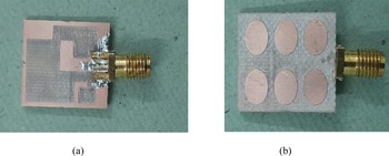
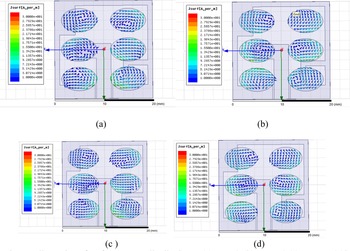
The top and bottom views of the fabricated prototype of the proposed antenna which uses the Agilent vector analyzer (N5230A: PNA-L) is depicted in Fig. 15. To know how CP waves are generated by the proposed antenna, the vector surface current distribution on the six EEBGs is analyzed by varying the phase at various time phases (ωt = 0°, 90°, 180°, 270°). Figure 16 depicts that at ωt = 0° and 90°, the vector surface currents are of the same magnitude and is in phase opposition at ωt = 180° and 270°, respectively. This indicates that since there is change in the phase, the rotation of the simulated surface current vectors is in the anticlockwise direction, indicating that left hand circular polarization (LHCP) is achieved.
(a) Top view and (b) bottom view of the proposed fabricated structure.

Illustration of surface current distribution at ωt = 0°, 90°, 180°, 270°.

Figure 17 not only shows the measured results of S 11, but also compares the axial ratio versus frequency with the simulated results. It is depicted that the proposed antenna offers measured impedance bandwidth of 36.9% which lies in the range 3.91–5.68 GHz and shows a good agreement with the simulated result of 33.33% (3.95–5.53 GHz). The measured AR bandwidth of 9.98% (4.09–4.52 GHz) also matches well with the simulated result of 8.53% (4.15–4.52 GHz). A slight difference in the measured and simulated result may be present because of fabrication tolerance and errors occurring in the measurement system. It is also observed from Fig. 18 that upon implementation of the EEBG on the antenna, the simulated peak gain in the AR bandwidth is 3 dBic. This is attributed to the surface waves being prohibited by the EEBG which leads to the enhancement of the gain.
Responses (measured and simulated) of S 11 and axial ratio versus frequency.

Responses (measured and simulated) of gain versus frequency.

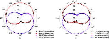
Figure 19 reveals the radiation characteristics of the proposed antenna in the E and H planes, respectively, at 4.33 GHz, depicting that in both the planes, LHCP waves are observed. Table 4 compares the proposed antenna with few of the reported CP antennas. From the evaluation of the comparison in Table 4, it is revealed that the proposed antenna is more compact with the impedance bandwidth and the AR bandwidth has improved as compared to the ones reported in Table 4.
Radiation pattern at 4.3 GHz: (a) E-plane and (b) H-plane.

Comparison table of reported CP antenna with our proposed antenna provided in the literature

Conclusion
An EEBG-based CP antenna which maneuvers at 4.3 GHz has been proposed in this paper. Using a 3 × 2 array EEBG on the substrate of the proposed antenna, an enhancement is observed in the antenna's performance with an impedance bandwidth of 36.9%, an AR bandwidth of 9.98%, and a gain of 3 dBic, thus making this antenna a contender to be utilized for WAIC systems.
 Dr. Shilpee Patil received her B.Tech. degree in Electronics & Communication Engineering from AKTU (formerly UPTU), Lucknow, India, and her M.Tech. degree in Digital Communication from GGSIP University, Delhi, India, in 2009. She pursued her Ph.D. degree in Electronics Engineering from AKTU, Lucknow, India. Her research interests are microstrip antennas, slot antennas, and circularly polarized microstrip antennas.
 Alka Verma received her B.E. degree in Electrical & Electronics from Bangalore University, Karnataka, India. She has completed her M.Tech. degree in Electronics Engineering from, Dr. A.P.J Abdul Kalam Technical University (formerly UPTU), Lucknow (U.P.), India and currently pursuing her Ph.D. degree from the same. Her areas of interests are microstrip antennas, electromagnetic band gap structures and circularly polarized microstrip antennas for wireless communications.
 Dr. Anil Kumar Singh was born in Jamalpur, Mirzapur (U.P.), India in 1976. He has completed his M.Tech. degree in Instrumentation and Control Engineering from NITTTR Chandigarh, India and his Ph.D. degree on Studies on Annular Ring Microstrip Antenna for different Applications from Electronics Engineering Department, Indian School of Mines (ISM), Dhanbad, India. He joined the Department of Electronics and Instrumentation Engineering, Institute of Engineering and Technology, M. J. P. Rohilkhand University, Bareilly as a lecturer in 2002. He has published more than 20 papers in national and international journals and conferences. His current research interest includes design and analysis of microstrip antennas.
 Dr. Binod Kumar Kanaujia is working as Professor in the School of Computational and Integrative Sciences, Jawaharlal Nehru University, New Delhi since August 2016. Dr. Kanaujia completed his B.Tech. in Electronics Engineering from KNIT, Sultanpur, India in 1994. He obtained his M.Tech. and Ph.D. in 1998 and 2004, respectively, from the Department of Electronics Engineering, I.I.T. B.H.U., Varanasi, India. He has a keen research interest in design and modeling of reconfigurable and circular polarized microstrip antennas. He has been credited to publish more than 150 research papers with more than 430 citations with an h-index of 12 in peer-reviewed journals and conferences. He successfully executed 4 research projects sponsored by several agencies of Government of India .e.g. DRDO, DST, AICTE, and ISRO. He is a member of several academic and professional bodies e.g. IEEE, Institution of Engineers (India), Indian Society for Technical Education and Institute of Electronics and Telecommunication Engineers of India.
 Dr. Suresh Kumar is working as an Associate Professor in the Department of Computer Science and Engineering in Netaji Subhas University and Technology, Delhi. He has a teaching experience of more than 15 years. He has completed his M.Sc. in Computer Science from KUK, Kurukshetra, India. He obtained his M.Tech. in Computer Science and Engineering from KUK, Kurukshetra, India and his Ph.D. from MDU, Rohtak, India. He has a keen research interest in database management system, operating system, Semantic Web, etc. He has published 12 research papers in peer-reviewed international journals and seven papers in international conferences.