


Introduction
The separation of oil–water mixtures is a widely utilized unit operation, used for handling a wide variety of mixtures from industry, including petroleum drilling and refining, fracking, waste-water treatment, mining, metal fabrication and machining, textile and leather processing, and rendering.[Reference Kajitvichyanukul and Wang1] The limitations on oil and grease content set by the US Environmental Protection Agency have become increasingly stringent over the years. The best available technology limit on oil and grease discharge in produced water is now 42 mg/L for any one day, with a 29 mg/L 30, consecutive-day average.[2] Depending on the industry, the oil and grease concentrations in the untreated effluent can typically range from a few hundred to 200,000 mg/L.[Reference Patterson3] The mixtures, produced from various industries, range from free oil and water, to surfactant-stabilized oil–water emulsions. Emulsions can be particularly difficult, energy intensive, and expensive to separate. The large volumes of contaminated mixtures, including from accidents such as the Deepwater Horizon spill, necessitate the development of durable, cost-effective means of selectively separating oil, and water mixtures with a high-volume throughput.
The difficulties associated with separating oil–water mixtures depend primarily on the dispersed phase size and its stability in the mixture. Mixtures of oil and water are classified, in terms of the diameter (d) of the dispersed phase, as free oil and water if d > 150 µm, a dispersion if 20 µm ≤ d ≤ 150 µm, or an emulsion if d < 20 µm.[Reference Kajitvichyanukul and Wang1] The stability of oil–water emulsions is greatly enhanced by the addition of surfactants, which decreases the interfacial tension between the oil and water phases, and hinders the coalescence of droplets.[Reference Mason, Wilking, Meleson, Chang and Graves4]
Numerous methods, including gravity separation, flotation, oil-absorbing materials, electrocoagulation, and flocculation, have traditionally been used to separate oil–water mixtures.[Reference Kajitvichyanukul and Wang1, Reference Adebajo, Frost, Kloprogge, Carmody and Kokot5–Reference Ichikawa9] Gravity separation or skimming is effective for separating free oil and water; however, it is unsuitable for the separation of smaller oil droplets or oil–water emulsions.[Reference Cheryan and Rajagopalan6] Flotation uses streams of air bubbles to enhance coalescence of smaller oil droplets, and it is typically followed by demulsification (i.e., conversion of an oil–water emulsion to a free oil and water) with chemicals and/or heat.[Reference Rubio, Souza and Smith8, Reference Al-Shamrani, James and Xiao10] Porous materials have also been widely used to absorb oil from water in case of oil-spills in the ocean. However, these materials absorb not only oil, but also water, due to a lack of selectivity, resulting in low separation efficiency.[Reference Toyoda and Inagaki11, Reference Gupta, Carrott and Carrott and Suhas12] Electric-field-driven coalescence or chemical addition can be effective for demulsifying emulsions, but these methods typically lead to significant energy consumption and secondary pollution.[Reference Ichikawa9, Reference Rios, Pazos and Coca13]
Membrane-based methods have become increasingly attractive for the separation of oil–water mixtures because they are relatively energy-efficient, can be readily used to separate a variety of industrial feed streams and provide consistent permeate quality.[Reference Kajitvichyanukul and Wang1, Reference Cheryan and Rajagopalan6] There are also some disadvantages associated with membrane-based oil–water separation; the biggest drawback is membrane fouling due to surfactant adsorption or pore plugging by oil droplets, resulting in diminished permeate flux.[Reference Song14, Reference Kong and Li15]
Research on membranes with selective wettability promises to improve the separation efficiency, as well as, imbue anti-fouling properties to oil–water separating membranes.[Reference Kajitvichyanukul and Wang1] If a membrane demonstrates a different wettability with water versus oil, it may be useful for the extremely efficient separation of oil–water mixtures.[Reference Kai, Ishii, Tsugaya, Miyano, Sourirajan and Matsuura16] This idea has led to a large number of membranes with selective wettability being developed and applied for separating a range of different oil–water mixtures.
Fundamentals of wettability
A surface's wettability is commonly characterized by a contact angle.[Reference Kota, Choi and Tuteja17] On a non-textured (or smooth) surface, the equilibrium contact angle θ is given by Young's relation[Reference Young18]:
 $${\rm cos}\,\theta = \displaystyle{{{\gamma _{{\rm SV}}} - {\gamma _{{\rm SL}}}} \over {{\gamma _{{\rm LV}}}}}.$$
Here γ is the interfacial tension between two phases and S, L, and V refer to the solid, liquid, and vapor phases, respectively. Thus, γ SV is the interfacial tension between the solid and vapor phases, and it is commonly called the solid surface energy. γ LV is typically referred to as the liquid surface tension. Based on previous literature,[Reference Tuteja, Choi, Ma, Mabry, Mazzella, Rutledge, McKinley and Cohen19–Reference Kota, Kwon and Tuteja21] the wettability of the solid surface can be classified into four regimes using contact angles for water: superhydrophobic (θ water > 150°), hydrophobic (HP) (θ water > 90°), hydrophilic (HL) (θ water < 90°), and superhydrophilic (θ water ~ 0°). Similarly, based on contact angles for a low surface tension liquid such as an oil or alcohol, surfaces are considered superoleophobic (θ oil > 150°), oleophobic (OP) (θ oil > 90°), oleophilic (OL) (θ oil < 90°), and superoleophilic (θ oil ~ 0°). Typically superhydrophobic or superoleophobic surfaces are referred to as super-repellent surfaces.
When a liquid droplet is placed on a textured (or rough) surface, the apparent contact angle (θ*) on the surface can be significantly different from the Young's contact angle θ. The addition of a liquid droplet to a textured surface may lead to either the ‘fully-wetted’ Wenzel[Reference Wenzel22] or the Cassie-Baxter[Reference Cassie and Baxter23] state, forming a composite solid–liquid–air interface. The Wenzel state exists when the liquid fully permeates and wets the textured surface, as seen in Fig. 1(a). In this state, the overall free energy reaches its minimum when the apparent contact angle becomes θ*, given by the Wenzel relation as[Reference Wenzel22]:
 $${\rm cos}\,{\theta ^{\ast}} = r\,{\rm cos}\,\theta. $$
Liquid droplets on textured surfaces. The (a) Wenzel and (b) Cassie–Baxter states are shown. In the diagrams, R is the feature radius, 2D is the inter-feature spacing, θ is the equilibrium contact angle, θ* is the apparent contact angle, and ψ is the texture angle. Adapted from Kota et al.[Reference Kota, Kwon and Tuteja21] © 2014 with permission from Nature Publishing Group.

Here r is the surface roughness defined as the ratio of the actual surface area to the projected surface area. Per its definition, r ≥ 1. Consequently, roughness yields a lower apparent contact angle for a liquid with θ < 90°. On the other hand, a higher apparent contact angle can be achieved for a liquid with θ > 90°.
The Cassie–Baxter state exists when air is trapped underneath the liquid droplet, forming a composite solid–liquid–air interface, as seen in Fig. 1(b). The apparent contact angles in this state can be calculated using the Cassie–Baxter relation,[Reference Cassie and Baxter23] given as:
 $${\rm cos}\,{\theta ^{\ast}} = {\,f_{{\rm SL}}}{\rm cos}\,\theta + {\,f_{{\rm LV}}}\,{\rm cos}\,\pi = {\,f_{{\rm SL}}}\;{\rm cos}\,\theta - {\,f_{{\rm LV}}}.$$
This relation describes how the apparent contact angle varies with the local areal fractions of the solid–liquid (f SL ) and the liquid–air (f LV ) interfaces in the vicinity of the triple-phase (solid–liquid–air) contact line.[Reference Choi, Tuteja, Mabry, Cohen and McKinley24] For most surfaces, the local and global areal fractions are equivalent.
Both the Wenzel and the Cassie–Baxter relations provide correlations between the apparent contact angle θ* and the Young's contact angle, θ, based on free-energy analysis. It is evident from Eqs. (2) and (3) that higher apparent contact angles can be encouraged in either the Wenzel state, if θ > 90° and r ≫ 1, or in the Cassie–Baxter state, if f SL ≪ 1. However, contact angle hysteresis (i.e., the difference between the advancing and receding contact angles) for the two states can be significantly different. The difference between the advancing (the maximum contact angle on a given surface) and receding (the minimum contact angle on a given surface) contact angles arises due to the presence of multiple metastable energy states on real, heterogeneous surfaces.[Reference Johnson and Dettre25] Typically, the contact angle hysteresis in the Wenzel state is larger than in the Cassie–Baxter state. This is because the solid–liquid interface is pinned on the textured surface.[Reference Quere26] By contrast, a composite solid–liquid–air interface in the Cassie–Baxter state leads to lower contact angle hysteresis and higher apparent contact angles when the contact area between the solid and the liquid is small.[Reference Quere26, Reference McHale, Shirtcliffe and Newton27] Consequently, the development of composite interfaces is essential for fabricating super-repellent surfaces.
Robust composite interfaces
Although the development of composite interfaces is necessary in engineering super-repellent surfaces, the details of the surface texture can significantly affect the stability of such an interface. Previous literature[Reference Marmur28–Reference Nosonovsky31] revealed that the formation of the stable Cassie–Baxter state is possible only if the Young's contact angle θ is greater than the local texture angle ψ. To illustrate this, two types of surface texture are considered here [Figs. 2(a) and 2(b)]. The surface texture shown in Fig. 2(a) (texture angle ψ > 90°) can lead to the formation of a composite interface when θ ≥ ψ. If θ < 90°, which is common for low surface tension liquids such as different oils on most surfaces, then the surface texture cannot maintain a stable composite interface, regardless of its surface energy or composition. However, for the same low surface tension liquid with θ < 90°, it is possible to support a composite interface as long as θ ≥ ψ. Such surface geometry with ψ < 90° is known as re-entrant texture. Re-entrant texture allows for the formation of a composite interface with low surface tension liquids, which may lead to OP or superoleophobic properties. Further design strategies for increasing the robustness (repellency with high breakthrough pressure) of a composite interface are described in the following section.
Composite interfaces and hierarchical texture. (a) A Cassie–Baxter state on a concave texture with ψ > 90° and θ > 90°. (b) A similar state exists with a lower surface tension liquid (θ < 90°) on convex, re-entrant texture (ψ < 90°). (c) A hierarchical texture combines coarser and finer textures to maximize the solid–air interface. Adapted from Kota et al.[Reference Kota, Kwon and Tuteja21] © 2014 with permission from Nature Publishing Group.
Design strategies for membranes with selective wettability
Systematic design of membranes for oil–water separation requires the parameterization of two important physical characteristics.[Reference Kota, Kwon, Choi, Mabry and Tuteja32] One is surface porosity, which affects the rate of liquid permeation through the membrane. It is evident from the Hagen–Poiseuille relation[Reference Batchelor33] that the volumetric flow rate Q ∝ r 4 (here r is the pore radius), when all other parameters are held constant. As the pore diameter decreases, viscous resistance to fluid flow through the membrane pores increases and consequently, the flux decreases. Although the Hagen–Poiseuille relation provides a correlation between the flow rate and the pore size, it does not account for the spacing between the pores, which also impacts flux. Previous work[Reference Tuteja, Choi, Ma, Mabry, Mazzella, Rutledge, McKinley and Cohen19, Reference Tuteja, Choi, Mabry, McKinley and Cohen30, Reference Choi, Tuteja, Chhatre, Mabry, Cohen and McKinley34, Reference Tuteja, Choi, McKinley, Cohen and Rubner35] discussed the spacing ratio, D*, which provides a dimensionless measure of surface porosity by considering both the pore size and spacing. For membranes possessing a predominantly cylindrical texture, such as interwoven meshes or fabrics,  $D_{{\rm cylinder}}^{\rm *} = (R + D)/R.$ Here R is the radius of a cylinder and 2D is the inter-cylinder spacing. Surface porosity increases with increasing D*. Thus, membranes with higher values of D* will show a higher permeation rate for a given contacting liquid.
The other critical physical characteristic is the breakthrough pressure (P breakthrough), defined as the maximum pressure differential across the membrane up until which the membrane prevents the permeation of a given liquid. To parameterize P breakthrough for a known surface texture and chemistry, previous work[Reference Tuteja, Choi, Mabry, McKinley and Cohen30, Reference Choi, Tuteja, Chhatre, Mabry, Cohen and McKinley34–Reference Chhatre, Choi, Tuteja, Park, Mabry, McKinley and Cohen36] discussed the robustness factor A*. This dimensionless value is obtained by scaling P breakthrough with respect to a reference pressure P ref = 2γ LV/l cap. Here 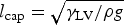 ${l_{{\rm cap}}} = \sqrt {{\gamma _{{\rm LV}}}/\rho g} $ is the capillary length of a liquid, ρ is the liquid density and g is the acceleration due to gravity. P ref is close to the minimum possible pressure differential across a millimeter-sized liquid droplet or a puddle.[Reference Tuteja, Choi, Mabry, McKinley and Cohen30] Consequently, large values of A* (A* ≫ 1) indicate the formation of a robust composite interface with a high P breakthrough. On the other hand, membranes with robustness factor A* ≤ 1, for a given contacting liquid, cannot support a composite interface, allowing the contacting liquid to penetrate into the pores and be fully imbibed. The robustness factor, for a surface possessing predominantly cylindrical texture, is given as[Reference Choi, Tuteja, Chhatre, Mabry, Cohen and McKinley34, Reference Chhatre, Choi, Tuteja, Park, Mabry, McKinley and Cohen36]:
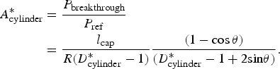 $$\eqalign{A_{{\rm cylinder}}^{\ast} & = \displaystyle{{{P_{{\rm breakthrough}}}} \over {{P_{{\rm ref}}}}} \cr & = \displaystyle{{{l_{{\rm cap}}}} \over {R(D_{{\rm cylinder}}^{\ast} - 1)}}\displaystyle{{(1 - {\rm cos}\,\theta )} \over {(D_{{\rm cylinder}}^{\ast} - 1 + 2{\rm sin}\theta )}}.}$$
For the effective separation of oil and water, membranes must be designed for a high permeation rate of one phase (e.g., water) and simultaneously, a high breakthrough pressure for the other phase (e.g., oil). This can be achieved by maximizing the two design parameters D* and A*.
However, D* and A* are strongly coupled for membranes with a periodic, cylindrical geometry,[Reference Tuteja, Choi, Mabry, McKinley and Cohen30, Reference Choi, Tuteja, Chhatre, Mabry, Cohen and McKinley34, Reference Chhatre, Choi, Tuteja, Park, Mabry, McKinley and Cohen36] as is evident from Eq. (4). The value of D* can be increased by either increasing D or reducing R, both of which lead to a decrease in A*. As discussed above, it is crucial to increase A* without affecting D* in order for the membranes to maintain a high rate of permeation for one phase (e.g., water), and a high breakthrough pressure for the other (e.g., oil) simultaneously. Such an enhancement can be achieved by introducing low surface energy materials on the solid surface, which leads to an increase in the values of Young's contact angle θ. Using this approach, the values of A* and the breakthrough pressure can be increased without changing the membrane geometry. However, lowering the surface energy of the solid may result in omniphobic surfaces, which repel both water and oil.[Reference Tuteja, Choi, Mabry, McKinley and Cohen30, Reference Golovin, Lee, Mabry and Tuteja37, Reference Hensel, Finn, Helbig, Braun, Neinhuis, Fischer and Werner38] Consequently, membranes with such surfaces may not allow selective permeation of one phase over the other phase. As described by Kota et al.,[Reference Kota, Kwon and Tuteja21] there are other design methods for increasing A* without affecting D* and vice versa. Utilizing a finer length scale texture, which decreases both R and D in such a way that the spacing ratio, D*, remains constant, will increase A* according to Eq. (4). On the other hand, D* can be increased, while A* remains constant, by adding hierarchical scales of texture. This is due to composite interfaces being the least stable on the largest scale of texture. Therefore, A*hierarchical ≈ A*micro, if both micro and nanostructures are present, while D*hierarchical ≫ D*micro due to the extra air captured within the multiple texture scales. Both A* and D* can be maximized in this way for fabricating a robust membrane with a high permeation rate.
Membranes possessing high A* values for one phase ( $A_{{\rm liquid}\,\,{\rm 1}}^{\rm *} \gg 1$), as well as small A* values for the other phase (
 $A_{{\rm liquid}\,\,{\rm 2}}^{\ast} \le 1$), allow for selective permeation of one liquid over the other. Such membranes can be achieved by developing surfaces that display significant differences between θ water and θ oil. In general, membranes can be categorized into four groups based on their contact angles with oil and water (Fig. 3): (A) HP/OL, (B) HL/OL, (C) HL/OP, and (D) HP/OP. In the following sections, we discuss recent developments and progress on membranes used for the separation of oil and water, and where they fall on the diagram shown in Fig. 3.
Membrane classification based on selective wettability for oil and water. A membrane is HP/OL when θ*water > 90° and θ*oil < 90°, HL/OL when θ*water < 90° and θ*oil < 90°, HL/OP when θ*water < 90° and θ*oil > 90°, and HP/OP when θ*water > 90° and θ*oil > 90°.
Membranes with selective wettability
Hydrophobic and oleophilic membranes
One variation of surfaces with selective wettability is a substrate that is both HP and OL. There are a few examples of this in nature, such as the lotus leaf and duck feathers. Many groups have been using this form of wettability to selectively separate oil and water mixtures by creating membranes that allow various oils to permeate while repelling water. Typically, such membranes are developed by coating a material with selective wettability onto porous substrates. A range of flexible and rigid substrates have been used for this purpose, including stainless steel and copper meshes, polymers, textiles, and filter papers. It should be noted that a number of previous publications fail to explicitly discuss if the measured contacts angles are advancing, receding, or static. In this review, we have provided the contact angles (advancing, receding, or static) exactly as described in the original publication.
Feng et al.[Reference Feng, Zhang, Mai, Ma, Liu, Jiang and Zhu39] spray coated an aqueous 30 wt% polytetrafluoroethylene (PTFE) emulsion, also containing an adhesive, a dispersant and a surfactant, onto a stainless-steel mesh. After half an hour in a 350 °C oven, the solvent evaporated. Some other organic, non-Teflon components were decomposed at this temperature, leaving behind a rough PTFE surface [Figs. 4(a) and 4(b)]. The surface contained micro and nanoscale roughness yielding a static θ*water = 156.2 ± 2.8° and θ*diesel oil = 0 ± 1.3° [Figs. 4(c) and 4(d)]. A free diesel oil and water mixture was poured over the developed membrane, which was mounted at approximately 45° in a glass tube to allow the lower density diesel oil to contact the membrane. It allowed for the separation of the diesel oil and water under gravity with >95% separation efficiency. PTFE was also used in conjunction with ZnO on a stainless-steel mesh by Wu et al.[Reference Wu, Chen, Qasim, Xia, Lei and Wang40] A 0.2 m zinc acetate solution was spray coated onto a cleaned mesh at 180 °C to form ZnO seeds. Following spray coating, the ZnO crystals on the mesh were grown further in a basic 0.1 m zinc acetate solution. Finally, the rough ZnO surface was spin coated with PTFE to create a low surface energy, hierarchically textured surface. This led to the formation of 1–2 µm sized flowers and nanorods. On the fabricated surface, static θ*water = 157° (sliding angle of <5°) and static θ*diesel oil was nearly 0°. To demonstrate the separation ability of the surface with diesel oil and water, droplets of each were simultaneously poured on the membrane. The water rolled off the surface, while the oil passed through the mesh. Tuteja et al.[Reference Tuteja, Choi, Ma, Mabry, Mazzella, Rutledge, McKinley and Cohen19] achieved a superhydrophobic and superoleophilic surface by electrospinning fluorodecyl polyhedral oligomeric silsesquioxane (POSS)-poly(methyl methacrylate) (PMMA) fibers onto a steel mesh. A fibrous mat with multiple scales of texture was achieved, with the f-POSS bringing additional roughness to the “beads on a string” fibers. θ*water = 161 ± 2° and θ*alkane = 0° for a membrane created by electrospinning a 9.1 wt% f-POSS in PMMA mixture. With the membrane suspended above a glass jar, a free octane and water mixture was cleanly separated.
Coated stainless steel meshes with selective wettability. (a,b) Textured Teflon coating on stainless steel mesh. (c,d) The superhydrophobic and superoleophilic nature of the mesh. Reproduced from Feng et al.[Reference Feng, Zhang, Mai, Ma, Liu, Jiang and Zhu39] © 2004 WILEY-VCH Verlag GmbH & Co. KGaA, Weinheim with permission from John Wiley & Sons, Inc. (e) The fabrication of a NDM treated mesh. (f,g) The separation of a hexane-water mixture with the apparatus at a 15° tilt angle. (h) Efficiencies for the separation of a variety of oils and water with the PDA–NMD mesh. Adapted with permission from Cao et al.[Reference Cao, Zhang, Tao, Li, Xue, Feng and Wei42] Copyright 2013 American Chemical Society.
Other groups have worked to chemically modify the underlying porous substrate. Wang et al.[Reference Wang, Cui, Mao and Chen41] used a stainless steel mesh modified with 1H, 1H, 2H, and 2H-perfluoroalkyltriethoxysilane. The surface displayed θ*water = 148.2° and θ*diesel = 0°. The developed membrane was used to separate two different oil and water mixtures: xylene/water (94.0 wt% water) and diesel/water (95.1 wt% water). The membrane allowed the oils to permeate through, while the water was retained. For the xylene/water system, the permeate contained 0.081 wt% water, whereas for the diesel/water system, 0.028 wt% water was measured in the permeate. Cao et al.[Reference Cao, Zhang, Tao, Li, Xue, Feng and Wei42] coated a stainless steel mesh with a polydopamine (PDA) film to act as an adhesive layer for the subsequent addition of n-dodecyl mercaptan (NDM) by a Michael's addition reaction [Fig. 4(e)]. The surface was covered with nano-papillae, which along with the NDM, yielded a HP surface. They found θ*water = 143.8 ± 1.0° and θ*diesel oil close to 0°. To test the oil–water separation ability, the membrane was placed inside a glass tube and the tube was tilted at a 15° angle to allow the oil to contact the mesh, despite the density difference between the oil and water [Figs. 4(f) and 4(g)]. Diesel/water, petroleum ether/water, and gasoline/water mixtures were separated with η = 98.1% efficiency for diesel/water and η > 99.7% for the other two separations [Fig. 4(h)].
Several groups have also used a modified copper mesh substrate for the separation. Wang et al.[Reference Wang, Song and Jiang43] achieved hierarchical copper surfaces by cathodic electrodeposition on copper meshes. Copper microclusters with 30–50 nm nanoparticles were developed on the mesh surface, and the textured copper meshes were soaked in a solution of n-dodecanoic acid for 12 h to yield θ*water = 158 ± 2° (and a 2° sliding angle), while θ*diesel oil was ≈0°. The developed superhydrophobic and superoleophilic membrane was found to be an effective diesel oil and water separator. Wang and Guo[Reference Wang and Guo44] used a similar electrochemical approach and deposited a ~2 µm thick coating of copper nanoparticles on top of a copper mesh followed by n-octadecyl thiol grafting [Figs. 5(a) and 5(b)]. θ*water = 154.1° and θ*chloroform = 0° were achieved, and a mixture of chloroform and water was separated by the prepared mesh mounted inside a tube [Figs. 5(c) and 5(d)]. Wang et al.[Reference Wang, Yao, Wu, Ma, Fan, Wang, Cheng, Lin and Yang45] utilized the nitric acid etching of a copper mesh, followed by chemically modifying the surface with hexadecanethiol [Figs. 5(e) and 5(f)]. The mesh showed θ*water = 153 ± 1° (<5° sliding angle), while diesel oil permeated through the mesh (θ*diesel = 0°). Diesel oil and water separation was demonstrated by pouring a mixture onto a mesh at the opening of a test tube. The diesel permeated through, while the water rolled off into a secondary beaker [Figs. 5(g) and 5(h)].
Copper mesh modification and separation ability. (a) and (b) SEM images of a copper mesh coated with Cu nanoparticles. (c,d) The separation of chloroform and water with the as-prepared copper mesh. Reprinted with permission from Wang and Guo.[Reference Wang and Guo44] © 2013 AIP Publishing LLC. (e,f) Etched and 1-hexadecanethiol treated copper mesh with 135 µm pore size and “nano-hills.” (g,h) Removal of diesel oil from water as the oil permeates and the water rolls off the mesh into the surrounding vial. Adapted with permission from Wang et al.[Reference Wang, Yao, Wu, Ma, Fan, Wang, Cheng, Lin and Yang45] Copyright 2009 American Chemical Society.
Liu et al.[Reference Liu, Cao, Lin, Chen, Feng and Wei46] fabricated a textured copper mesh with HP/OL wetting properties, which could be reversibly switched to HL and underwater OP [Figs. 6(a) and 6(b)]. A copper mesh was textured with Cu(OH)2 nanoneedles by oxidation with 0.05 m K2S2O8 and 1.0 m NaOH [Figs. 6(c)–6(e)]. The as-prepared membrane was found to be superhydrophilic. After surface modification using a self-assembling monolayer of stearic acid, formed by dipping the membrane in a 0.05 m solution for 5 min, the membrane became superhydrophobic and superoleophilic with θ*water = 155.4 ± 1.3° and θ*diesel = 0°. This mesh could separate diesel oil and water mixtures by allowing oil to permeate through, while retaining water [Figs. 6(f) and 6(g)]. Interestingly, the surface wettability was altered to superhydrophilic and underwater superoleophobic by immersion in tetrahydrofuran (THF) for 5 min due to the desorption of stearic acid. Such wettability reversal allowed water to permeate through while retaining diesel oil, leading to switchable oil–water separation [Figs. 6(h) and 6(i)].
The switchable wetting of stearic acid modified Cu(OH)2 nanoneedles on a copper mesh. (a,b) Schematics illustrating the switchable wettability for the mesh. Stearic acid self-assembled monolayer (SAM) provides superhydrophobicity, while THF desorbs this layer to provide a superhydrophilic and underwater superoleophobic mesh. SEM images are provided, with high magnification insets, of (c) a mesh with Cu(OH)2 nanoneedles, (d) a SAM modified mesh, and (e) a THF desorbed mesh. (f) A diesel–water mixture was tested on the membrane showing that the SAM modified mesh allowed diesel permeation (g), while the THF desorbed mesh permeated water (h,i). Adapted with permission from Liu et al.[Reference Liu, Cao, Lin, Chen, Feng and Wei46] Copyright 2014 American Chemical Society.
Copper meshes have also been coated with polymers to achieve HP/OL properties. Crick et al.[Reference Crick, Gibbins and Parkin47] deposited Sylgard 184 silicone elastomer (PDMS) on copper meshes using aerosol-assisted chemical vapor deposition (AACVD). The PDMS-based elastomer was dissolved in chloroform and used in the AACVD process to develop 3–5 µm tall micropillars on the mesh surface, which became superhydrophobic with θ*water = 152°–167° for various mesh sizes. The toluene, petroleum ether, and hexane contact angles on the fabricated mesh were θ*oil = 0°. The membrane was used to separate mixtures of water/toluene, water/petroleum ether, and water/hexane. Almost no water permeated through the mesh, and greater than 99% of the oil phase could be removed from the water.
Not all membranes have used metal meshes as the substrate; polymeric substrates have also been found to work well. The porous polymer substrates with desired wetting properties may be formed directly, or they may be modified through additional texture and chemical treatments, as necessary. Shang et al.[Reference Shang, Si, Raza, Yang, Mao, Ding and Yu48] formed a nanofiber membrane substrate from electrospun cellulose acetate. Thermosetting 2,2-bis(3-m-trifluoromethylphenyl-l-3,4-dihydro-2H-1,3-benzoxazinyl)propane (BAF-tfa) monomer and SiO2 nanoparticles (7–40 nm) were added on top by dip coating, followed by polymerization at 190 °C. The HP polymer is referred to as fluorinated polybenzoxazine (F-PBZ) and binds the nanoparticles to the cellulose acetate fibers. The particles add hierarchical roughness, while the F-PBZ provides a low surface energy. The fiber diameter and roughness were controlled by varying the wt% of BAF-tfa and SiO2 nanoparticles in the dip coating solutions [Fig. 7(a)]. A static contact angle of up to θ*water = 161° was measured, along with a θ*dichloromethane = 3°. This membrane was shown to quickly separate a dichloromethane and water (50%, v/v) mixture [Fig. 7(b)]. Tang et al.[Reference Tang, Si, Ge, Ding, Liu, Zheng, Luo and Yu49] continued this work, with a F-PBZ coating on an electrospun substrate, to improve the physical properties of the membrane. Their synthesis procedure was very similar, but the materials were slightly different. The cellulose acetate was exchanged for poly(m-phenylene isophthalamide) with added multi-walled carbon nanotubes. Also, a new version of F-PBZ was utilized; the new monomer was 2,2-bis(3-octadecyl-3,4-dihydro-2H-1,3-benzoxazinyl)hexafluoro propane (BAF-oda). The coating allowed the membrane to achieve θ*water = 161° and θ*dichloromethane = 0° and to cleanly separate a mixture of dichloromethane and water (50% v/v). By adjusting the polymers used in this work, this new membrane was stable up to 350 °C, resistant to hot water at 80 °C, and showed a mechanical strength of 40.8 MPa.
F-PBZ/SiO2 nanoparticle-modified, electrospun cellulose acetate membranes. (a) The fabrication strategy for a nanofibrous membrane produced using electrospinning and (b) the separation ability of the fabricated membrane tested with a 50% v/v mixture of dichloromethane and water. Adapted from Shang et al.[Reference Shang, Si, Raza, Yang, Mao, Ding and Yu48] © 2012 with permission from The Royal Society of Chemistry.
Huang et al.[Reference Huang, Si, Tang, Zhu, Ding, Liu, Zheng, Luo and Yu50] developed another method for achieving HP/OL membranes with fluorinated benzoxazine using silica nanofibers, alumina (Al2O3) nanoparticles, and 3-[3-(trifluoromethyl)phenyl]-2H-benzoxazine-6-carbaldehyde (BAF-CHO) monomer [Fig. 8(a)]. θ*water = 161° and θ*rapeseed oil = 0°, and the membrane could gravity separate a surfactant-stabilized water-in-petroleum ether, micron-scale emulsion [Figs. 8(b) and 8(c)]. The petroleum ether phase was shown to pass through the membrane under gravity, while retaining the water [Fig. 8(b)]. The filtrate showed no water droplets, indicating almost complete separation [Fig. 8(c)].
F-PBZ/Al2O3 nanoparticle-modified, electrospun silica nanofibrous (SNF) membranes. (a) Procedure for the synthesis of relatively durable nanofibrous membranes (b) The gravity-driven separation of a span80-stabilized water-in-petroleum ether nanoemulsion. (c) The optical clarity of the oil after separation is apparent in the photograph and optical micrographs. Adapted from Huang et al.[Reference Huang, Si, Tang, Zhu, Ding, Liu, Zheng, Luo and Yu50] © 2013 with permission from The Royal Society of Chemistry.
Zhang et al.[Reference Zhang, Shi, Zhang, Liu, Jin and Jiang51] utilized a phase-inversion process to form a hierarchical poly(vinylidene fluoride) (PVDF) membrane for separating surfactant-stabilized emulsions. The PVDF solution was first prepared in N-Methylpyrrolidone followed by drop casting onto a PTFE substrate. This was subsequently dipped in water for phase inversion, and the resulting PVDF membrane was peeled off the PTFE substrate. The prepared PVDF membrane showed microparticles, with surface nanostructure, interconnected by fibers. The membrane showed θ*water = 158° and θ*dichloromethane < 1°, and the separation capability was tested with water-in-oil emulsions (5–20 µm droplets), with and without surfactant. The oils used included: petroleum ether, toluene, isooctane, and dichloromethane. The membranes could separate the various water-in-oil emulsions under gravity with η > 99.95% separation efficiency.
Multiple groups have been successful in modifying commercially available filter papers to impart them with HP/OL properties. Wang et al.[Reference Wang, Li and Lu52] fabricated HP/OL membranes by dip coating a cellulose filter paper in a solution containing polystyrene and PDMS-modified, HP silica nanoparticles. The polystyrene and silica nanoparticles were used in a 1:1 mass ratio for optimum results. A static θ*water = 157 ± 2° was measured, while diesel oil spread and permeated through the surface (θ*diesel oil = 0°). Using this membrane, mixtures of diesel oil and water, with volume ratios ranging from 1:15 to 1:1 (oil:water), demonstrated a separation efficiency η > 96% upon pouring over the membrane. Du et al.[Reference Du, Wang, Chen and Chen53] fabricated a polystyrene film, with embedded PTFE nanoparticles (200 nm), on top of filter paper (15–20 µm pore size) to achieve superhydrophobic and superoleophilic membranes. PTFE and polystyrene nanoparticle colloidal solutions, 6 and 1 wt%, respectively, were mixed in a 3:2 ratio. The filter paper was dipped in the solution for 30 min, and then heated at 220 °C for 20 min to melt only the polystyrene nanoparticles, while retaining roughness from the PTFE nanoparticles. The θ*water = 155 ± 2° and θ*hexane = 0° on the developed membranes. To test the separation ability, a hexane and water mixture was poured over the membrane inside a funnel. The membrane allowed only the hexane to permeate through, yielding a η > 99% separation efficiency.
Carbon is also useful, when used in conjunction with polymers and filter papers, for forming composite membranes that are HP/OL, as well as electrically conductive. Asthana et al.[Reference Asthana, Maitra, Buchel, Tiwari and Poulikakos54] utilized combinations of carbon black (CB), graphene nanoplatelets (GNP), and carbon nanotubes (CNT) with Capstone ST-100 fluoroacrylic polymer to achieve conducting, HP/OL membranes. A 2 wt% solution of the fluoropolymer and a separate 2 wt% solution of the various carbon fillers were made. The two solutions were mixed to achieve the desired carbon filler to polymer ratio. Different ratios of carbon fillers and fillers-to-polymer were tested until the best overall mixture for water-impalement resistance and conductivity was found to be a 1:1:2 CB:GNP:Polymer mass ratio. The prepared solution mixture was drop cast onto cellulose filter paper and cured at 160 °C to melt the polymer. The rough hierarchical surface showed superhydrophobicity with θ*water > 150° and oleophilicity with θ*mineral oil = 0°. A mineral oil (ρ oil = 0.838 g/mL) and water (1:1 v/v) mixture was completely gravity separated with the CB/GNP membrane inside a funnel. The funnel geometry allowed the lower density oil to contact the membrane.
Shi et al.[Reference Shi, Zhang, Zhang, Liu, Wang, Jin and Jiang55] fabricated films composed of purely single-walled carbon nanotubes (SWCNTs). This film met the need for achieving the thinnest membrane possible, while maintaining a useful pore size for maximum permeation rates. A SWCNT suspension was filtered through a mixed cellulose ester (MCE) membrane to form the film. Immersion in acetone dissolved the MCE membrane and the SWCNT film floated to the surface [Fig. 9(a)]. Membranes with thicknesses of 30–120 nm and corresponding pore sizes of 200–20 nm were fabricated. For static droplets on the 70 nm thick membrane, θ*water = 94° and θ*dichloromethane = 0°. The film was placed on a ceramic support for liquid separation testing [Fig. 9(b)], and several different emulsions, both surfactant-free and surfactant-stabilized water-in-oil emulsions, were separated, including water-in-petroleum ether and span80-stabilized water in toluene emulsions [Fig. 9(c)]. All separations showed no water droplets in the oil permeate, and the oil was tested to be >99.95 wt% pure, while maintaining very high permeation rates up to 107,140 L/m2/h/bar for the 30 nm thick film (obtained using surfactant-free water-in-petroleum ether emulsion).
SWCNTs and silicone nanofilament membranes. (a) A TEM image of a 70 nm thick SWCNT film showing its interlaced structure. (b) The SWCNT film supported by a steel hoop and (c) the selective permeation of oil from an emulsion using this film. Reproduced from Shi et al.[Reference Shi, Zhang, Zhang, Liu, Wang, Jin and Jiang55] © 2013 WILEY-VCH Verlag GmbH & Co. KGaA, Weinheim with permission from John Wiley & Sons, Inc. (d,e) Silicone nanofilaments grown on a polyester textile. (f) The simple separation of an octane and water mixture. Reproduced from Zhang et al.[Reference Zhang and Seeger56] © 2011 WILEY-VCH Verlag GmbH & Co. KGaA, Weinheim with permission from John Wiley & Sons, Inc.
Zhang and Seeger[Reference Zhang and Seeger56] modified polyester textiles to achieve superhydrophobic and superoleophilic membranes through the chemical vapor deposition of trichloromethylsilane, which grew silicone nanofilaments on the textile [Figs. 9(d) and 9(e)]. The rough, fibrous surface helped achieve superhydrophobicity (θ*water > 150°), with a water roll-off angle of ω = 3° and θ*octane = 0°. A mixture of octane and water was separated by pouring it over the membrane [Fig. 9(f)].
Li et al.[Reference Li, Shi, Chen, Zhang, Guo, Su and Liu57] achieved superhydrophobic coatings by adding family VIII and IB metal oxide nanocrystals and octadecyl thiol to textiles (65% polyester and 35% cotton). Nanocrystal suspensions were formed and the textiles were dipped in them for 5 min. After washing and drying the textiles, they were dipped in 20 mm octadecyl thiol for 24 h to become HP/OL. They obtained θ*water > 150° and θ*hexane = 0°. A mixture of hexane and water was poured on the membrane mounted in a tube, and the hexane permeated quickly while retaining the water. No water was found in the hexane permeate.
Kavalenka et al.[Reference Kavalenka, Hopf, Schneider, Worgull and Holscher58] turned to a biodegradable and non-toxic alternative for achieving a superhydrophobic and superoleophilic surface. They processed lignin and wood fibers to create a microhaired membrane by hot pulling their “liquid wood” polymer, Arbofill® spruce. The surface fibers were about 5 µm in diameter and >200 µm long. A static θ*water = 153.8 ± 2.1° and an oil contact angle θ*Total Azolla ZS 10 = 0° were measured. The oil and water separation ability was demonstrated by placing drops of Total Azolla ZS 10 (hydraulic oil) and water mixture onto the surface; the oil permeated, while the water was retained.
Although many different methods have now been developed for separating oil and water mixtures with a HP/OL membrane, there are inherent difficulties with this type of wettability. First, gravity separation is prevented if water contacts the membrane before oil, due to its higher density and the hydrophobicity of the membrane. Secondly, these membranes encounter fouling, as oils adsorb to the membrane surface, which decreases the desired oil flux.[Reference Maartens, Jacobs and Swart59, Reference Hu and Scott60] This can add significant downtime, cleaning, and membrane replacement costs when using these types of membranes. To overcome these disadvantages, membranes with other selective wettabilities have also been explored.
Hydrophilic and oleophilic membranes
Recently, a new concept of underwater superoleophobic surfaces has been proposed, which was inspired by the non-wetting behavior of oil droplets on fish scales underwater.[Reference Liu, Wang, Wei, Song and Jiang61] From Young's relation [see Eq. (1)], it is clear that HL surfaces in air can become OP when underwater.[Reference Liu, Wang, Wei, Song and Jiang61, Reference Xue, Liu and Jiang62] In the presence of HL rough structures, water readily wets and fills all the cavities present on the surface, leading to a composite solid–oil–water interface. Similar to the composite solid–oil–air interface formed on superoleophobic surfaces in air, this new composite interface prevents the permeation of oil droplets, yielding underwater superoleophobicity. Such superhydrophilic and underwater superoleophobic surfaces exhibit excellent oil fouling resistance, which is attributed to the low affinity for oil droplets when submerged in water.[Reference Liu, Wang, Wei, Song and Jiang61] However, these types of membranes may not be effective in stop-and-go operations where the loss of water would allow oil contamination to occur. A number of membranes that display superhydrophilicity in air and underwater superoleophobicity have been fabricated.
One of the first reports on superhydrophilic and underwater superoleophobic membranes was from Xue et al.[Reference Xue, Wang, Lin, Chen, Liu, Feng and Jiang63] in 2011. They fabricated polyacrylamide (PAM) hydrogel-coated membranes, which consisted of rough hydrogel coatings on top of porous, stainless steel substrates [Fig. 10(a)]. The PAM hydrogel-coated mesh showed underwater superoleophobicity with a θ*1,2-dichloroethane = 155.3 ± 1.8°. They also demonstrated that the hydrogel coating reduced the affinity for oil droplets, which could foul typical membranes, through a reduction in the adhesion force of an oil droplet from 46.5 ± 2.3 µN, on the uncoated stainless steel mesh, to 0.8 ± 0.3 µN for the underwater, hydrogel-coated mesh. Utilizing this underwater, superoleophobic membrane, they achieved separations of various free oil–water mixtures including: crude oil, gasoline, and diesel with η > 99% [Figs. 10(b) and 10(c)]. Recently, Teng et al.[Reference Teng, Lu, Ren, Zhu, Wan and Jiang64] developed superhydrophilic in air and underwater superoleophobic hydrogel-coated membranes that exhibit stability under harsh environmental conditions. Poly (3,4-ethylenedioxythiophene)-poly(styrenesulfonate) (PEDOT-PSS) hydrogel meshes with hierarchical structures were fabricated by in situ polymerization on a titanium (Ti) mesh substrate [Fig. 10(d)]. The membrane displayed θ*water = 0° in air and θ*1,2-dichloroethane = 156° contact angle underwater. They demonstrated that the membranes would separate a series of oil–water mixtures containing acidic, basic, and aqueous salt solutions, with η > 99.9% [Figs. 10(e) and 10(f)]. Furthermore, the membranes achieved η = 99.5% even after 50 separation operations, demonstrating their durability. Zhang et al.[Reference Zhang, Lu, Tao, Liu, Gao, Feng and Wei65] fabricated chitosan (CTS)-coated membranes inspired by the anti-oil-fouling behavior of shrimp shells. A coating of CTS on a rough copper mesh [Fig. 10(g)] maintained underwater superoleophobicity with low oil adhesion in pure and hyper-saline aqueous solutions. Similar to shrimp shells, the CTS -coated mesh was HL (θ*water = 7.1 ± 3.0°) and OL (θ*1,2-dichloroethane = 11.8 ± 2.0°) in air, whereas it possessed underwater superoleophobicity (θ*1,2-dichloroethane = 155.9 ± 1.0° in deionized water; θ*1,2-dichloroethane = 153.0 ± 1.4° in seawater). The prepared membranes separated free oil–water mixtures containing various oils, including: hexane, gasoline, diesel, and crude oil, as well as, saline (2 m NaCl) mixtures with these oils, with η > 99% [Figs. 10(h) and 10(i)]. Further, they demonstrated that the membranes could separate a range of oil–water mixtures in hyper-saline and broad pH conditions after fully cross-linking CTS. Lu et al.[Reference Lu, Chen, Liu, Cao, Xu, Wei and Feng66] fabricated cellulose hydrogel-coated nylon membranes. The as-prepared membrane showed superhydrophilicity in air with θ*water = 0° and underwater superoleophobicity with a θ*1,2-dichloroethane > 150°. They demonstrated that the membrane was effective in the separation of multiple free oil–water mixtures including: n-hexane, petro-ether, gasoline, and diesel.
Hydrogel and CTS coated meshes for oil and water separations. (a) 50 µm, stainless steel mesh coated with a PAM hydrogel. (b,c) Water, from a crude oil–water mixture, selectively permeated through the membrane. Reproduced from Xue et al.[Reference Xue, Wang, Lin, Chen, Liu, Feng and Jiang63] © 2011 WILEY-VCH Verlag GmbH & Co. KGaA, Weinheim with permission from John Wiley & Sons, Inc. (d) SEM image of a PEDOT-PSS hydrogel coated Ti mesh. (e,f) The mesh was used to separate a diesel and 1 m sulfuric acid mixture without any degradation. Reproduced from Teng et al.[Reference Teng, Lu, Ren, Zhu, Wan and Jiang64] © 2014 WILEY-VCH Verlag GmbH & Co. KGaA, Weinheim with permission from John Wiley & Sons, Inc. (g) CTS coated on a rough Cu mesh with nanopapillae. (h) The water permeated out of a crude oil and water mixture and (i) a high separation efficiency was seen for several oils, even in saline conditions. Adapted with permission from Zhang et al.[Reference Zhang, Lu, Tao, Liu, Gao, Feng and Wei65] Copyright 2013 American Chemical Society.
Although hydrogel-coated meshes have been successfully fabricated and have demonstrated their utility in separating oil–water mixtures, the binding of hydrogel to the underlying porous substrate is often very weak, leading to low membrane durability. Jing et al.[Reference Jing, Wang, Lin, McGinn, Na and Zhu67] demonstrated that poly(glycidyl methacrylate) (PGMA) could be grafted onto stainless steel mesh by thermal treatment. Subsequently, polyacrylamide-co-poly(acrylic acid) (PAM-co-PAA) hydrogel particles were grafted onto the PGMA-modified stainless steel mesh. This led to static θ*water = 4.4 ± 0.4° in air, and a static underwater θ*dodecane = 157.1 ± 2.6°. The PAM-co-PAA-coated membranes were used to separate different free oil–water mixtures, including water–dodecane and water–rapeseed oil mixtures.
In addition to hydrogels, various other HL materials have also been utilized for coating porous meshes to engender superhydrophilicity and underwater superoleophobicity. Dong et al.[Reference Dong, Li, Shi, Wang, Guo and Liu68] fabricated HL graphene oxide (GO) nanosheet-coated membranes using a stainless steel mesh substrate [Fig. 11(a)]. Due to the HL GO coating, and the mesh morphology, a static θ*water < 10° in air, while the static underwater θ*oil > 150° for various oils. As-prepared GO-coated membranes were used to separate a number of free oil–water mixtures, including: n-hexane, gasoline, diesel, toluene, etc. with η > 90% separation efficiencies [Figs. 11(b) and 11(c)].
GO and zeolite-coated mesh membranes. (a) GO coated on 38 µm pore-size stainless steel mesh. (b) The separation apparatus showing the permeation of water and rejection of hexane (dyed red) by the GO-coated mesh. (c) High separation efficiency was seen for a variety of oils. Adapted from Dong et al.[Reference Dong, Li, Shi, Wang, Guo and Liu68] © 2014 with permission from The Royal Society of Chemistry. (d) An SEM image of the zeolite-coated mesh film (ZCMF-12) and (e) a demonstration of its ability to selectively remove water from crude oil. (f) The residual oil content in water for different oils after the separation. Adapted from Wen et al.[Reference Wen, Di, Jiang, Yu and Xu69] © 2013 with permission from The Royal Society of Chemistry. (g)–(i) A zeolite membrane on top of stainless steel mesh separated chloroform (dyed red) and water mixtures efficiently while maintaining high dichloromethane contact angles over 14 separations. Reprinted from Zeng et al.,[Reference Zeng and Guo70] Copyright 2014, with permission from Elsevier.
Due to their hydrophilicity and chemical stability, zeolites have also attracted research interest in the field of oil–water separation. Wen et al.[Reference Wen, Di, Jiang, Yu and Xu69] developed zeolite-coated membranes for gravity-driven oil–water separation. Such membranes were fabricated by growing pure-silica zeolite, silicalite-1, crystals on a stainless steel mesh [Fig. 11(d)]. The as-prepared membrane exhibited θ*water < 10° in air, whereas all contact angles for various oils underwater, including petroleum ether, soybean oil, diesel, and crude oil, were θ*oil > 150°. High separation efficiency of various oils, including crude oil, diesel, and soybean oil, was achieved due to the superhydrophilicity and underwater superoleophobicity of the zeolite-coated membrane surface [Figs. 11(e) and 11(f)]. Zeng and Guo[Reference Zeng and Guo70] demonstrated, in another report, that the zeolite-coated membranes possessed good reusability [Figs. 11(g) and 11(h)] without a decline in separation efficiency [Fig. 11(i)]. Liu et al.[Reference Liu, Chen, Lu, Cao, Xue, Li, Feng and Wei71] proposed a much simpler approach to fabricate superhydrophilic in air, and underwater superoleophobic, membranes. Chemical oxidation of a copper mesh leads to the formation of Cu(OH)2 micro- and nanoscale hierarchical structure on the mesh surface [Fig. 12(a)]. This prepared mesh exhibited superhydrophilicity with θ*water = 0° in air, and underwater superoleophobicity with θ*1,2-dichloroethane = 166.2 ± 1.3°. The membranes could separate various mixtures of organic solvents or oil and water with η > 99.99% [Figs. 12(b)–12(d)]. They also demonstrated the reusability and stability of the membranes with no degradation after 60 separations [Fig. 12(e)].
Hierarchically structured copper (II) hydroxide on copper mesh. (a) An SEM image of Cu(OH)2 nanoneedles and microscale spherical crystals on top of a copper mesh. (b,c) Selective permeation of water and retention of diesel was achieved. (d) The oil content in the collected water, and the separation efficiency for a variety of oils. (e) Separation efficiency over extended numbers of separations. Reproduced from Liu et al.[Reference Liu, Chen, Lu, Cao, Xue, Li, Feng and Wei71] © 2013 WILEY-VCH Verlag GmbH & Co. KGaA, Weinheim with permission from John Wiley & Sons, Inc.
In addition to metal meshes, there have also been reports of superhydrophilic in air, and underwater superoleophobic, polymer membranes. Zhu et al.[Reference Zhu, Zhang, Wang, Pei, Zhang and Jin72] fabricated zwitterionic polyelectrolyte brush [poly(3-(N-2-methacryloxyethyl-N, N-dimethyl) ammonatopropanesultone) or PMAPS]-grafted PVDF membranes. After PMAPS grafting, the PVDF membrane displayed a static θ*water = 11° in air, while all static underwater contact angles for oil, including petroleum ether, soybean oil and hexane, were θ*oil > 150°. Utilizing this membrane, they demonstrated the separation of a series of dispersed oil–water mixtures, including isooctane, hexane, diesel, and soybean oil. After the separations, the oil content in the water-rich permeates was less than 10 ppm for all systems. Chen et al.[Reference Chen and Xu73] developed hybrid polypropylene microfiltration membranes, which were optimized by grafting on PAA and depositing HL, nano-sized CaCO3 minerals. In conjunction with the HL PAA layer, the CaCO3 coating traps water, in an aqueous environment, to form a hydrated layer on the membrane pore surface. This leads to underwater superoleophobicity with θ*1,2-dichloroethane > 150°. The membrane could separate free oil–water, as well as, surfactant-stabilized oil-in-water emulsions (140 nm–5.56 µm), with η > 99% separation efficiency. Yang et al.[Reference Yang, Liao, Huang, Wu, Wan and Xu74] developed a one-pot approach to modify polypropylene membranes through the co-deposition of PDA and polyethyleneimine (PEI) [Fig. 13(a)]. The PDA/PEI-coated membranes showed better stability in an alkaline environment due to the covalent cross-linking between PDA and PEI. They demonstrated that the membranes could separate a 1,2-dichloroethane-in-water emulsion with η > 98% separation efficiency [Fig. 13(b)]. In their recent work,[Reference Yang, Pi, Liao, Huang, Wu, Huang and Xu75] nanosilica particles were added to the PDA/PEI-coated polypropylene membranes [Fig. 13(c)]. The membranes could be used for the separation of a variety of surfactant-stabilized oil-in-water emulsions (polydisperse: 150 nm to >10 µm) with η > 99% separation efficiency [Fig. 13(d)].
Modified polypropylene membranes for oil–water separation. (a) A schematic illustrating the treatment of a polypropylene membrane with dopamine and PEI, and (b) its use for separating a dichloroethane in water emulsion. Adapted from Yang et al.[Reference Yang, Liao, Huang, Wu, Wan and Xu74] © 2014 with permission from The Royal Society of Chemistry. (c) Method for producing silica and PDA/PEI decorated polypropylene membranes that (d) show high water permeation, while rejecting several oils. Adapted with permission from Yang et al.[Reference Yang, Pi, Liao, Huang, Wu, Huang and Xu75] Copyright 2014 American Chemical Society.
In other reports, the polymer membrane was directly fabricated by electrospinning. Ahmed et al.[Reference Ahmed, Lalia, Hilal and Hashaikeh76] fabricated poly(vinylidene fluoride)-co-hexafluoropropylene (PVDF-HFP), non-woven, nanofiber membranes by electrospinning a PVDF–HFP solution. Immersing the membrane in an ionic liquid and cellulose solution, followed by ionic liquid removal, yielded a cellulose/PVDF–HFP composite, resulting in enhanced mechanical properties and wettability [Fig. 14(a)]. Cellulose-coated membranes displayed θ*water = 0° in air, whereas θ*dichloromethane = 169 ± 3° underwater. They demonstrated separations of oil-in-water emulsions (unstated size), using corn oil, gasoline, and crude oil, with η > 99.98% separation efficiency [Figs. 14(b)–14(e)]. Raza et al.[Reference Raza, Ding, Zainab, El-Newehy, Al-Deyab and Yu77] developed multi-layered, nanofibrous membranes with a polyacrylonitrile (PAN)/polyethylene glycol (PEG) base, and an additional in situ cross-linked, polyethylene glycol diacrylate (PEGDA) nanofiber layer spun on top [Fig. 14(f)]. These membranes separated free oil–water mixtures, as well as, surfactant-stabilized soybean oil-in-water emulsions, between 5 and 40 µm in size [Fig. 14(g)].
Electrospun composite polymer membranes for water purification. (a) Process for the fabrication of cellulose/PVDF–HFP composite membranes. 10 wt% oil-in-water emulsions were made with (b) corn oil, (c) gasoline, (d) motor oil, and (e) crude oil. In each window (b)–(e), the emulsion is on the left and the aqueous permeate is on the right. Reprinted from Ahmed et al.,[Reference Ahmed, Lalia, Hilal and Hashaikeh76] Copyright 2014, with permission from Elsevier. (f) Fabrication procedure for cross-linked PEGDA nanofibers supported on PAN/polyethylene glycol nanofibrous (x-PEGDA@PG NF) membranes. (g) Soybean oil (dyed red) and water were separated using the x-PEGDA@PG NF membrane. Adapted from Raza et al.[Reference Raza, Ding, Zainab, El-Newehy, Al-Deyab and Yu77] © 2014 with permission from The Royal Society of Chemistry.
In addition to polymer membranes, inorganic fiber filters have also been utilized for oil–water separation. Liu et al.[Reference Liu, Patel and Liu78] fabricated zwitterionic poly(sulfobetaine methacrylate)-grafted (pSBMA) glass fiber filters using surface-initiated atom transfer radical polymerization. pSBMA is a superhydrophilic polymer due to its strong electrostatic interaction with water. Thus, in air, the water contact angle of pSBMA-treated glass was θ*water = 8–15°, while underwater θ*hexadecane = 162–169°. The prepared membranes demonstrated complete separation of free hexadecane–water mixtures. Chen et al.[Reference Chen, Xue, Liu, Lu, Cao, Sun and Feng79] fabricated superhydrophilic and underwater superoleophobic membranes by combining a quartz fiber mesh with silica gel, which was further enhanced by adding 1,2-bis(triethoxysilyl)ethane (BTSE) and PAM. Because the silica gel is stable in acidic and saline environments, the membrane demonstrated the ability to separate free crude oil–water mixtures without being deteriorated by such harsh conditions.
Practical applications of HL or superhydrophilic membranes in oil–water separations are limited by contamination from low surface energy oil.[Reference Yang, Zhang, Xu, Zhu, Men and Zhou80, Reference Howarter and Youngblood81] Once the membrane is fouled by oil, it is difficult to remove the adsorbed oil. This leads to decreased separation performance, and necessitates periodic washing of the membranes, resulting in higher operating costs. To overcome this limitation, self-cleaning membranes have also been studied. Zhang et al.[Reference Zhang, Zhong, Cha and Wang82] fabricated self-cleaning membranes using layer-by-layer (LBL) assembly of sodium silicate and TiO2 nanoparticles on stainless steel mesh. The integration of self-cleaning ability using TiO2 enables the convenient removal of contaminants by ultraviolet (UV) light. The developed membranes could separate free gasoline–water mixtures under gravity [Figs. 15(a) and 15(b)]. Furthermore, they evaluated the membrane's self-cleaning capability by measuring water contact angles on the membranes after five cycles of oleic acid contamination and UV illumination-based recovery [Fig. 15(c)]. This showed that the cleaned membranes still exhibited hydrophilicity similar to the uncontaminated membranes. Gao et al.[Reference Gao, Liu, Sun and Ng83] fabricated sulfonated graphene oxide (SGO) membranes with hierarchically nanostructured TiO2 spheres. The TiO2 spheres, bound by the HL SGO nanosheets, endowed this composite membrane with excellent mechanical and chemical durability. They demonstrated that the membrane could separate various surfactant-stabilized oil-in-water emulsions (200 nm), including toluene, crude oil, vegetable oil, and diesel, at various temperatures and ionic concentrations [Figs. 15(d)–15(f)]. The membrane was also found to recover its superhydrophilicity upon UV light illumination. Sawai et al.[Reference Sawai, Nishimoto, Kameshima, Fujii and Miyake84] fabricated Ti membranes with a TiO2 surface through the calcination of a Ti mesh at 500 °C for 4 h. They observed that the water contact angle on a membrane reduced from θ*water = 48.8 ± 3.9° to less than 5° upon UV irradiation. Conversely, underwater contact angles for oils (heptane, dodecane, and hexadecane) increased to static θ*oil > 160°. This indicates that UV irradiated-TiO2 exhibits extremely high oil repellency in water. Utilizing this membrane, they demonstrated the separation of free hexadecane–water mixtures.
TiO2 composite membranes. (a) and (b) Sodium silicate and TiO2 nanoparticles on top of a stainless steel mesh selectively removed water from gasoline (c) Anti-fouling properties shown by water contact angle changes on the silicate/TiO2 coated mesh in five cycles of oleic acid contamination and UV illumination-based recovery. Adapted from Zhang et al.[Reference Zhang, Zhong, Cha and Wang82] under Creative Commons License CC-BY 3.0 (d) A graphene-TiO2 membrane could separate a surfactant-stabilized toluene-in-water emulsion. (e,f) Water, with varying concentrations of salt, was also removed from crude oil at different temperatures. Adapted from Gao et al.[Reference Gao, Liu, Sun and Ng83] © 2014 with permission from The Royal Society of Chemistry.
Although membranes with superhydrophilic and underwater superoleophobic properties can be successfully used for gravity-driven separation of oil–water mixtures, and are more resistant to fouling, they are unsuitable for the separation of free water-in-oil or water-in-oil emulsions. This is because both oil and water easily permeate through them, unless every pore within the membrane is pre-wet by water. Consequently, oil permeates through the membrane if water dries out from even a single pore within the superhydrophilic membrane, which can typically happen in a matter of minutes.[Reference Kota, Kwon, Choi, Mabry and Tuteja32]
Hydrophilic and oleophobic membranes
As discussed in previous chapters, HP/OL membranes are unsuitable for most gravity-driven separations. Although HL/OL membranes are applicable for the gravity-driven separation of oil-in-water emulsions, they do not work for free oil–water or water-in-oil emulsions, unless they are repeatedly pre-wet by water. HL/OP membranes are expected to overcome these limitations. However, it has been considered challenging to fabricate such membranes due to the surface tension of water (γ LV = 72.1 mN/m) being significantly higher than that of oils (γ LV = 20–30 mN/m).
In our recent work,[Reference Kota, Kwon, Choi, Mabry and Tuteja32] we successfully fabricated hygro-responsive membranes that are both superhydrophilic and superoleophobic in air and underwater. We utilized a polymer blend consisting of 20 wt% 1H, 1H, 2H, 2H-heptadecafluorodecyl polyhedral oligomeric silsesquioxane (fluorodecyl POSS) and cross-linked polyethylene glycol diacrylate (x-PEGDA) as the coating material. With a porous substrate, such as stainless steel mesh or polyester fabric, water readily wet the coated surface (i.e., θ*water = 0°), while θ*rapeseed oil, adv = 152° [Fig. 16(a)]. We showed that such selective wettability of water over oil is attributed to the surface reconfiguration of the fluorodecyl POSS + x-PEGDA coating [Figs. 16(b) and 16(c)]. It was demonstrated that the membrane could separate surfactant-stabilized oil-in-water and water-in-oil emulsions (emulsion diameter: 10–20 µm) under gravity. We also demonstrated that the membrane could separate virtually all types of oil–water mixtures, solely under gravity, with η > 99% separation efficiency [Fig. 16(d)]. A continuous separation apparatus was engineered utilizing a hygro-responsive membrane and a conventional HP/OL membrane operating in tandem [Fig. 16(e)]. During the continuous separation of oil–water emulsions, the fluxes for both water and oil did not decline over a period of 100 h [Fig. 16(f)].
Hygro-responsive membranes for oil–water separation. (a) Water (blue) and rapeseed oil (red) contact angles on a stainless steel mesh (top) and a polyester fabric (bottom) dip coated in 20 wt% fluorodecyl POSS + x-PEGDA blend. (b) Optical microscopy image of a 20 wt% fluorodecyl POSS + x-PEGDA blend surface in air and (c) underwater showing the surface reconfiguration. (d) A four-component mixture of water, hexadecane, 30:70 (v:v) water-in-hexadecane emulsion, and a 50:50 (v:v) hexadecane-in-water emulsion was separated with a 400 mesh stainless steel membrane coated with 20 wt% fluorodecyl POSS + x-PEGDA blend. (e) A continuous separation apparatus separated 30:70 (v:v) water-in-hexadecane emulsions stabilized by polysorbate80. It used a 20 wt% fluorodecyl POSS + x-PEGDA blend membrane (superhydrophilic and OP) on the bottom, and a Desmopan9370 coated sidewall membrane (HP/OL). (f) The hexadecane and water fluxes for the continuous apparatus over a period of 100 h. Reprinted from Kota et al.[Reference Kota, Kwon, Choi, Mabry and Tuteja32] © 2012 with permission from Nature Publishing Group.
In addition to polymer blends, synthesis of polymers possessing HL and OP constituents has also been proposed for fabricating HL/OP coating materials. Yang et al.[Reference Yang, Zhang, Xu, Zhu, Men and Zhou80] developed a superhydrophilic and superoleophobic nanocomposite coating. They first synthesized a polymer with HL and OP constituents through the reaction of poly(diallyldimethylammonium chloride) (PDDA) with sodium perfluorooctanoate (PFO). Superhydrophilic and superoleophobic surfaces were fabricated by spray casting PDDA–PFO/silica nanoparticles onto glass, stainless steel mesh, or paper. On the coated glass surface, the water contact angle in air was found to be θ*water = 0°, while θ*hexadecane = 155 ± 1°. Separation membranes were fabricated by spray casting polymer-silica nanoparticles onto stainless steel mesh, and they demonstrated separation of free hexadecane–water mixtures under gravity. In another report,[Reference Yang, Song, Yan, Tang and Li85] PDDA was substituted with CTS for the HL constituent. CTS–PFO polymer and silica nanoparticles were sprayed onto stainless steel mesh, developing membranes with θ*water = 0° and θ*hexadecane = 157 ± 1°, which separated a free hexadecane–water mixture under gravity. Zhu et al.[Reference Zhu, Loo and Bai86] fabricated membranes using PVDF, as the base matrix polymer, blended with additive polymers containing perfluoroalkyl PEG surfactant chains. The developed membranes exhibited anti-organic and anti-biofouling properties. In another report,[Reference Zhu, Tu, Wee and Bai87] they demonstrated that the membrane could separate crude oil or hexadecane-in-water emulsions (1–50 µm) with η > 98% separation efficiency.
Howarter and Youngblood[Reference Howarter and Youngblood88] modified glass fiber membranes by bonding Zonyl® FSN-100, a perfluorinated polyethylene glycol (f-PEG), to them using 3-Isocyanatopropyldimethylchlorosilane as a linker. The f-PEG oligomer, containing both a low surface energy segment and a polar one, led to HL/OP surfaces on various membranes, with pore sizes ranging from 10–20 µm to 145–174 µm. The best static contact angles were achieved on the 10–20 µm pore-sized membrane, θ*water = 30° and θ*hexadecane = 105°, in air, and it maintained θ*hexadecane > 140° underwater. For testing oil rejection capability, a 12:1 volume ratio of water to hexadecane was mechanically dispersed to form an, approximately, 10 µm diameter oil-in-water emulsion. This was gravity fed through the modified 10–20 µm pore-sized membrane and only 2.6 ± 1.2 wt% of the hexadecane permeated through the membrane with the water. The larger pore-sized membranes permitted <6 wt% of hexadecane to permeate through, while maintaining several times greater flow rates, as expected. The f-PEG layer was ≤5 nm thick and should not significantly alter the initial membrane pore size. Larger pore-sized membranes have greater flow rates, but may allow smaller oil droplets to permeate through.
Yoon et al.[Reference Yoon, Na, Choi, Latthe, Swihart, Al-Deyab and Yoon89] developed superhydrophilic and OP stainless steel meshes (initially 42–60 µm pore size) using a mixture of PDDA, PFO, and 10–25 nm diameter silica particles. This provided a dense composite coating with a thickness of approximately 2.8 µm. The PDDA and silica provided HL components to the coating, and the PFO provided low-energy, mobile fluorinated chains. The static θ*water = 0° and θ*hexadecane = 95°. The separation ability was tested by mounting the prepared mesh in glassware and pouring 50 mL of hexadecane on it, followed by 100 mL of water. The water displaced the oil and passed through in 12 min, while retaining the oil. It remained OP for 2 weeks with 97% water recovery. Repeating the separation 30 times, with aqueous cleaning, and drying, performed between each trial, tested the mesh reusability. In addition, a graphene plug was added after the mesh to show that organics such as methylene blue could be removed from the water after the separation. The 2 cm thick plug decreased the permeation rate from 800,000 to 6000 L/m2/h/bar.
Hydrophobic and oleophobic membranes
In contrast to membranes with selective wettability of water over oil or vice versa, HP/OP membranes prevent permeation of both oil and water. To utilize HP/OP membranes (omniphobic) for the separation of oil–water mixtures, pressure must be selectively exerted on either the water or oil phase, leading to P breakthrough, water < P applied < P breakthrough, oil or vice versa.
An electric field provides a facile route for tuning the wettability of polar (or conducting) liquids. The decrease in the macroscopic contact angle for a polar liquid droplet on a dielectric, in response to an external electric field, is known as electrowetting on a dielectric (EWOD) [Figs. 17(a)–17(d)]. It is described by the Young–Lippmann equation[Reference Berge90]:
 $${\rm cos}\,{\theta ^{{\rm ew}}} = cos\,\theta + \displaystyle{{{\varepsilon _0}{\varepsilon _{\rm d}}} \over {2{\gamma _{12}}d}}{V^2}.$$
θ ew is the macroscopic electrowetting contact angle, θ is Young's contact angle, ε0 is the vacuum permittivity, εd is the dielectric permittivity, γ 12 is the interfacial tension between the liquid and surrounding medium, d is the dielectric thickness, and V is the voltage applied. Utilizing the EWOD phenomenon, we[Reference Kwon, Kota, Li, Sohani, Mabry and Tuteja91] recently developed an on-demand oil–water separation technology, where the separation is triggered upon the application of an electric field. For effective on-demand separation of oil–water mixtures, both oil and water must be retained above the membrane initially. Thus, we first developed an omniphobic membrane by dip-coating nylon mesh with a blend of 50 wt% fluorodecyl POSS and cross-linked polydimethylsiloxane (x-PDMS). The membrane retained both water and oil before the application of an electric field. When an external electric field was applied across the conducting liquid (e.g., water) and the electrode at the membrane, the conducting liquid, initially in the Cassie–Baxter state on the porous membrane, transitioned to the Wenzel state. This is because the Maxwell stress exerted on the conducting liquid surface pulls it outward along the surface normal. By contrast, a non-conducting liquid (e.g., oil) does not undergo such a transition [see Fig. 17(e)]. When transitioning to the Wenzel state, increasing the applied pressure, P applied, sags the liquid–air interface [Fig. 17(f)] until it reaches a critical texture angle, ψ cr. This angle is where the surface can withstand the greatest pressure P critical before entering the Wenzel state. For cylindrical surface geometry, such as with our membranes, P critical is given by[Reference Kwon, Kota, Li, Sohani, Mabry and Tuteja91]:
 $${P_{{\rm critical}}} = \displaystyle{{{\gamma _{12}}sin\,(\theta - {\psi _{{\rm cr}}})} \over {D + R - R\,{\rm sin}\,{\psi _{{\rm cr}}}}},$$
where
 $${\psi _{{\rm cr}}} = \theta - {\rm cos}{^{ - 1}}\left( {\displaystyle{{R\,\,{\rm sin}\,\theta} \over {R + D}}} \right).$$
Electrowetting of an omniphobic surface. (a) and (b) Hexadecane's contact angle on a non-textured 50 wt% fluorodecyl POSS + x-PDMS substrate was unchanged by the application of a 1.5 kV potential, while (c,d) water's contact angle decreased significantly. (e) The macroscopic contact angles for water and hexadecane on the non-textured surface as a function of applied voltage. (f) A diagram illustrating the pressure-induced liquid–air interface sagging. (g) The EWOD effect was used to separate hexadecane (red) and water (blue) on-demand. Adapted from Kwon et al.[Reference Kwon, Kota, Li, Sohani, Mabry and Tuteja91] © 2012 WILEY-VCH Verlag GmbH & Co. KGaA, Weinheim with permission from John Wiley & Sons, Inc.
As in Fig. 17(f), R is the cylinder radius and D is half of the cylinder spacing. Consequently, upon applying a sufficient electric field, a conducting liquid transitions to the Wenzel state and permeates through the membrane, whereas a non-conducting liquid is retained above the membrane. Utilizing this preferential transition, we demonstrated the on-demand separation of free oil and water, oil-in-water emulsions, and water-in-oil emulsions, with η > 99.9% separation efficiency [Fig. 17(g)]. Such on-demand separation could be useful for the remote operation of oil–water separation units, microfluidic valves, and lab-on-a-chip devices.
Conclusions and future outlook
The development of membranes with selective wettability is an ongoing process, which aims to more effectively meet today's needs for efficient oil and water separation. They are a promising alternative to traditional separation methodologies. The numerous sources of oily wastewater and increasingly strict environmental guidelines necessitate a highly effective, economical, and durable membrane, with a long service life, for purifying waste streams and spills. As discussed throughout, there are different selective wettabilities to choose from, and many different methods for achieving each one of them. The type of membrane used will depend on the waste stream composition, fouling potential, and the system employed for the separation (on-demand, gravity fed, high pressure, etc.). The form of oil, whether free or emulsified, will indicate the pore size for the membrane and thus is directly related to the permeation rate through the membrane. All these parameters must be taken into account for utilizing membranes with selective wettability.
A multitude of selective wettability systems have been used to successfully separate oil and water mixtures with greater than 99.9% efficiency, but the future lies in imparting these wetting properties to membranes that withstand high trans-membrane pressures, have greater permeation rates of the desired liquid, are anti-fouling, and can be scalably manufactured at a reasonable cost. Developing a selective wettability membrane with all these characteristics will require creative solutions, and provides a range of intellectual and research challenges. Such membranes will help meet the growing needs for waste and byproduct treatment in a wide variety of fields.
Acknowledgments
We thank Dr. Ki-Han Kim and the Office of Naval Research (ONR) for financial support under grant N00014-12-1-0874. We also thank Dr. Charles Y. Lee and the Air Force Office of Scientific Research (AFOSR) for financial support under grant FA9550-10-1-0523. We also thank the National Science Foundation and the Nanomanufacturing program for supporting this work through grant no. 1351412. EP would like to acknowledge support through the National Science Foundation Graduate Research Fellowship under Grant No. DGE 1256260.



