I. INTRODUCTION
Mo2FeB2 ternary boride based cermets have been widely applied to wear resistance parts such as injection molding machine parts, hot copper extruding dies, and tools making due to their superior intrinsic properties, for example, high hardness, high melting point, and excellent corrosion and oxidation resistance. Reference Takagi1–Reference Takagi3 In the past few years, the effects of preparation techniques Reference Takagi3 and additional elements such as Cr, Reference Takagi, Komai, Ide, Watanabe and Kondo4 Ni, Reference Takagi, Komai, Ide, Watanabe and Kondo5 Mn Reference Pang, Zheng, Wang and Wang6 and V Reference Yu, Zheng, Liu, Zheng and Xiong7 on the properties of Mo2FeB2-based cermets have been well studied. In particular, Takagi Reference Takagi3 proposed the criteria for the production of boride base cermets, that is, selecting a suitable boride which coexists with the metal matrix for the formation of a two phase structure, avoiding the formation of a brittle third phase, preventing grain growth during sintering and forming a liquid phase between the boride and metal matrix to obtain full densification of a sintered product. Complying with these criteria, the technique called “reaction boronizing sintering” was exploited, through which the cemented boride with desired microstructure and excellent mechanical properties can be obtained. Inspired by the perfect performance of Mo2FeB2 ternary boride based cermets, several researchers have made efforts to investigate the preparation of Mo2FeB2-based cermets coatings. Reference Wang and Li8–Reference Peng, Pan and Zhang10 Surface engineering techniques such as reactive thermal spraying and laser cladding have been used to fabricate the Mo2FeB2-based cermets coatings, which have significantly improved the hardness and wear resistance of the substrate.
However, few studies have focused on the joining of Mo2FeB2-based cermets, especially the joining of Mo2FeB2-based cermets and dissimilar materials. As we know, compared with the traditional structural materials such as carbon steel and stainless steel, Mo2FeB2-based cermets have many disadvantages, for instance, high cost and complicated preparation technology, which would limit their applications. In this case, it is suggested to apply it as the key parts in the applications, indicating the needs for joining to other materials. 316L stainless steel is another extensively used material in industries, such as injection molding machine, paper and pulp, oil and gas and petrochemical industries due to its excellent corrosion and oxidation resistance as well as good formability and durability. Reference Yan, Liu, Tao and Lu11–Reference Chen, Lu, Lu and Lu13 Thus, in this study, it involves the joining of Mo2FeB2-based cermets and 316L stainless steel, which is expected to be applied in the manufacture of injection molding machine and wear plate. As is well known, the joining of dissimilar materials is generally more challenging than that of similar materials on account of differences in the physical, chemical and mechanical properties. Reference Kaçar and Baylan14
In this study, the joint of Mo2FeB2-based cermets and 316L stainless steel was successfully achieved by gas tungsten arc welding (GTAW) with no fillers. The weldability was investigated by plate rigid restraint cracking (PRRC) test and transverse rupture strength (TRS) was measured by the three-point bending test. Microstructure, microhardness, and corrosion behavior in different zones of the welded joint were studied. Research results can provide practical foundations of GTAW for Mo2FeB2-based cermets and 316L stainless steel dissimilar alloys.
II. MATERIALS AND METHOD
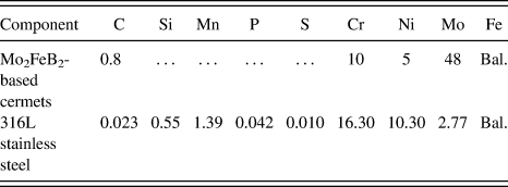
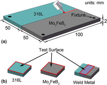
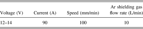
The base metals used in this study were Mo2FeB2-based cermets and commercial 316L stainless steel in 2.0 mm sheet form. The powder mixtures of Mo2FeB2-based cermets were prepared from FeB alloy powder, pure Mo, carbonyl Ni, carbonyl Fe, pure Cr and graphite and ball-milled in acetone to an average particle size of 3–5 μm. Then, the milled powder were dried, pressed to green compacts and sintered in vacuum at 1523 K for 25 min. The TRS and hardness of Mo2FeB2-based cermets used in this paper were 1715 MPa and 90.3 HRA respectively. Table I displays the chemical composition of Mo2FeB2-based cermets and 316L stainless steel. The schematic of welding process is illustrated in Fig. 1(a), with the welding parameters listed in Table II.
Chemical composition (wt%) of Mo2FeB2-based cermets and 316L stainless steel.

(a) Schematic diagram of the welding process, (b) specimens prepared for electrochemical measurements.

Process parameters used in GTA welding.

After welding, the welded joint was cut into typical cross section. Then, the metallographic samples were ground with abrasive papers and polished by 1.5 μm diamond paste before observation. The microstructure in different regions of the joint was studied with scanning electron microscope (SEM) in backscattered electron (BSE) mode. Chemical composition was investigated by energy-dispersive spectrometer (EDS). X-ray diffraction (XRD) line profiles were measured using an x-ray diffractometer with Cu Kα radiation (λ = 0.154056 nm) and the scanning rate was set as 8 °/min with a scan step of 0.02°. The thermal properties of the Mo2FeB2-based cermets were tested by differential scanning calorimeter (DSC) under argon atmosphere at the heating rates of 20 °C/min and cooling rates of 40 °C/min. Besides, the microhardness distribution was measured by a Digital Microhardness Tester with a load of 500 g for 10 s dwell time.
For the electrochemical measurements, specimens, i.e., Mo2FeB2-based cermets, 316L stainless steel and the weld metal (WM), were prepared as shown in Fig. 1(b). Afterward, each specimen was grinded, polished, and embedded in polyester resin after establishing the electrical contact on the back. In this study, a conventional three-electrode electrochemical cell was used. The platinum foil and the saturated calomel electrode were used as the counter and reference electrode respectively. Potentiodynamic polarization tests were carried out in 3.5 wt% NaCl solution at room temperature with a scanning rate of 1 mV/s. Stable open circuit potential (OCP) was obtained within 30 min before polarization and the scanning potential started from a potential of 200 mV below OCP to the potential where the current density reached 10 mA/cm2. To ensure the repeatability of the corrosion results, each sample was measured at least three times. Furthermore, the surface morphologies of Mo2FeB2-based cermets and WM after the electrochemical tests were investigated by SEM.
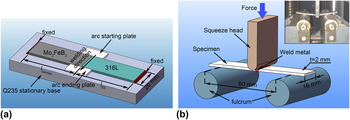
To assess the weldability of dissimilar metals between Mo2FeB2-based cermets and 316L stainless steel by GTAW, PRRC test was carried out. The schematic illustration of PRRC test is shown in Fig. 2(a) and the welding parameters are shown in Table II. The arc starting and arc ending plates were used in the test to avoid the deleterious influence of arc starting and ending on the formation of joint. TRS of the joint was investigated by the three-point bending test with a loading rate of 1 mm/s as shown in Fig. 2(b).
(a) Schematic illustration of PRRC test, (b) Schematic of the three-point bending test.

III. RESULTS AND DISCUSSION
A. Weldability and bending test
The weldability of dissimilar metal between Me2FeB2-based cermet and 316L stainless steel was evaluated by PRRC test which is widely used to assess the cold cracking susceptibility. According to previous study, the restraint intensity R can be calculated by the Eq. (1):
 $$R = {P \over {SB}}\quad ,$$
where P is the restraint force; S represents the decrement of weld root gap; B is the width of specimen. In the present work, the dissimilar metals are jointed without weld gap. Therefore, S can be attributed to the shrinkage of WM, which can be expressed as follows:
 $$S = {\lambda _{{\rm{SS}}}} + {\lambda _{{\rm{cermet}}}} + {\lambda _{\rm{w}}}\quad ,$$
where λss, λcermet, and λw stand for the deformation of 316L stainless steel, Mo2FeB2-based cermets and WM caused by the restraint force respectively. From knowledge of material mechanics, λss, λcermet, and λw can be given by Eqs. (3)–(5):
 $${\lambda _{{\rm{ss}}}} = {P \over {{E_{{\rm{SS}}}}hB}}{l_{{\rm{SS}}}}\quad ,$$
 $${\lambda _{{\rm{cermet}}}} = {P \over {{E_{{\rm{cermet}}}}hB}}{l_{{\rm{cermet}}}}\quad ,$$
 $${\lambda _{\rm{w}}} = {P \over {{E_{\rm{w}}}hB}}{l_{\rm{w}}}\quad ,$$
where E SS, E cermet, and E w are the Young's modulus of 316L stainless steel, Mo2FeB2-based cermets and WM respectively; l SS, l cermet, and l w represent the length of 316L stainless steel, Mo2FeB2-based cermets and WM respectively; h is the thickness of base metal. Supposing the WM is completely rigid (λw → 0), the restraint intensity can be expressed as Eq. (6):
 $$R = {{{E_{{\rm{SS}}}}{E_{{\rm{cermet}}}}h} \over {{E_{{\rm{SS}}}}{l_{{\rm{cermet}}}} + {E_{{\rm{cermet}}}}{l_{{\rm{SS}}}}}}\quad ,$$
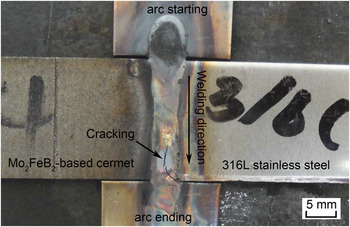
The schematic illustration of PRRC test is shown in Fig. 2(a). In this work, l cermet was set as 45 mm unchangeably, while l SS was set as 45, 60, and 75 mm respectively. According to Eq. (6), the restraint intensity was approximately 5.5, 4.5, and 3.9 GPa, respectively. It can be found that there was no macro-scale cracking when the restraint intensity were 4.5 and 3.9 GPa. However, it appeared as the restraint intensity increased to 5.5 GPa, as shown in Fig. 3. Based on the crack forming time (soon after welding) and location (fusion zone), we can deduce that it may be weld solidification cracking whose occurrence must satisfy two conditions: (i) thermally or mechanically imposed restraint and (ii) a crack-susceptible microstructure rather than cold cracking. Reference Lippold15 According to the shrinkage-brittleness theory, Reference Lippold15,Reference Medovar16 the crack-susceptible microstructure results from the persistence of liquid films along the solidification boundaries in the WM. Central to this theory is the existence of an “effective interval” of solidification that occurs below the “coherency” temperature. In this effective interval, the occurrence of solid–solid bridging is essential to cracking, which allows strain to accumulate in the structure. In general, cracking susceptibility will be greatest at the composition where the “effective interval” is the largest. As discussed in the below microstructure characterization section, the WM was consisted of M3B2 phase and hypoeutectic microstructure. The M3B2 phase and primary phase (α) may contribute to the solid–solid bridging and the eutectic microconstituent (α + β) is likely to form the liquid film during effective interval, which would lead to the cracking susceptibility in WM.
Macrograph of the weld joint after PRRC test.

The TRS was measured from a three-point bending test as shown in Fig. 2(b). In the three-point bending test, TRS was calculated from Eq. (7) (Ref. Reference Chung, Yap, Chandra and Lim17):
 $${\sigma _{\rm{f}}} = {{3PL} \over {2b{h^2}}}\quad ,$$
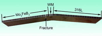
where L is the distance between the fulcrums; b and h are the width and thickness of the specimen respectively; P is the maximum force exerted on the specimen prior to fracture. According to Eq. (7), TRS was calculated to be around 1984 MPa. Figure 4 shows the macroscopic image of specimen after the bending test. As can be seen, the fracture locates at the Mo2FeB2-based cermets instead of the WM, indicating that the TRS of WM is greater than 1984 MPa. Also, it implies that the TRS of WM is greater than that of Mo2FeB2-based cermets.
Macrograph of the sample after three-point bending test.

B. Crystalline phases
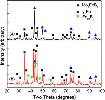
Figure 5 shows the XRD patterns of Mo2FeB2-based cermets and WM. In both profiles, the backgrounds were corrected, Kα2 profiles were subtracted and the peaks were indexed. As can be seen in Fig. 5(a), it contains two main phases, i.e., Mo2FeB2 or M3B2 hard phase and the γ-Fe binder, in the Mo2FeB2-based cermets. Note that M3B2 is a complex ternary boride (Fe, Mo, Cr)3B2 formed by Mo2FeB2 and Mo, Cr at high temperature according to reactions i.e., Equations (8) and (9) (Ref. Reference Wang and Li8) as follows:
 $${\rm{Cr}} + {\rm{M}}{{\rm{o}}_2}{\rm{Fe}}{{\rm{B}}_2} \to {\left( {{\rm{Mo}},{\rm{Fe}},{\rm{Cr}}} \right)_3}{{\rm{B}}_2}\quad ,$$
 $${\rm{Fe}} + {\rm{F}}{{\rm{e}}_2}{\rm{B}} + {\left( {{\rm{Mo,Fe,Cr}}} \right)_3}{{\rm{B}}_2} \to {\rm{Liquid}} + {\left( {{\rm{Mo,Fe,Cr}}} \right)_3}{{\rm{B}}_2}\quad .$$
XRD patterns of different samples: (a) Mo2FeB2-based cermets, (b) WM.

As for the WM [Fig. 5(b)], a M23C6 (where M represents a metal) type boride phase Fe23B6 was detected except for M3B2 hard phase and γ-Fe phase. According to Yu's research, Reference Yu, Zheng, Liu, Pang, Zheng and Xiong18 the M23B6 phase is composed of Mo, Fe, Cr and B with an atomic ratio close to 16:6:1:6 and a little Ni. Moreover, it was found that the diffraction peaks of Fe23B6 were left-shifted, which could be explained by the replacement of Fe with Mo, Cr and Ni elements.
C. Microstructure characterization
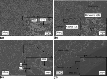
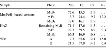
The BSE images of Mo2FeB2-based cermets are shown in Fig. 6(a). As can be seen, the granular white colored grains are distributed uniformly in the dark phases. The granular grains and the dark phases were identified as M3B2 phase and γ-Fe based binder respectively through the EDS and XRD measurements. The EDS results of M3B2 phase and γ-Fe based binder are listed in Table III. It should be noted that the boron content was not taken into consideration in this study because of the insensitivity of EDS techniques to boron. It can be seen that Mo is enriched in M3B2 phase and Fe is concentrated in the γ-Fe based binder, whereas the distribution of Cr is relatively homogeneous.
BSE images in different zones of the joint: (a) Mo2FeB2-based cermets, (b) HAZ near Mo2FeB2-based cermets, (c) WM, (d) interface of WM and 316L stainless steel.

Major alloy contents (wt%) in different zones of the joint measured by EDS.

Figure 6(b) displays the BSE image of HAZ located on the side of Mo2FeB2-based cermets. It can be found that a small amount of M3B2 boride hard phase dissolves into the γ-Fe based binder as shown at site A, accompanied by the growth and coalescence of other M3B2 grains. In particular, the tiny white particles at site A are supposed to be the remaining M3B2 phase after the dissolution of original M3B2 phase. EDS analysis (shown in Table III) indicates that they have the similar chemical composition with the M3B2 phase in the Mo2FeB2-based cermets base metal. According to previous research, Reference Ming, Yu, Liu and Zheng19–Reference Yu, Liu and Zheng22 the microstructure evolution in HAZ adjacent to the fusion line could be explained by the solution-reprecipitation mechanism caused by the reheating in the welding process. During the weld thermal cycle, the original relatively coarse M3B2 grains could act as seeds for further growth, with the dissolution of M3B2 grains in smaller size. In particular, Yu et al. Reference Yu, Liu and Zheng22 reported that the growth and coalescence of M3B2 grains occurred within a short soaking time when the sintering temperature was about 1320 °C.
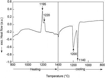
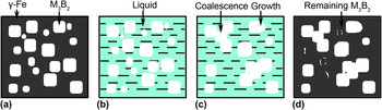
To investigate the microstructure evolution in HAZ adjacent to the fusion line, DSC measurement was carried out at the heating rates of 20 °C/min and cooling rates of 40 °C/min. The DSC curves of Mo2FeB2-based cermets are shown in Fig. 7. The endothermic peaks at 1195 and 1220 °C on the heating curve correspond to the exothermic peaks at 1140 and 1200 °C on the cooling curve respectively. These peaks are produced by reactions involving either formation or solidification of a liquid phase. According to Ide's research, Reference Ide and Ando21 during the liquid phase sintering process, the boride hard phase Mo2FeB2 was formed in the compact initially by the reaction 2Mo + 2FeB = Mo2FeB2 + Fe and later by the reaction of 2Mo + 2Fe2B = Mo2FeB2 + 3Fe before the liquid formation. At the next stage, the liquid phase L1 and L2 were formed successively as the temperature increased. In particular, L2, which had a high solubility for Mo2FeB2, was responsible to the solution–reprecipitation process in the sintering process. Therefore, in this work, it was considered that the first peak at 1195 °C on the heating curve could be attributed to the liquid transformation of γ-Fe based binder (cooling from L2 in the sintering process) via γ-Fe → Liquid. As the temperature increased, the solution-reprecipitation process was triggered at about 1220 °C, leading to the second peak. Figure 8 shows the schematic illustration of microstructure evolution in HAZ during the welding process. The microstructural schematic of Mo2FeB2-based cermets is shown in Fig. 8(a). During the weld thermal cycle, the γ-Fe based binder transforms to liquid phase at about 1195 °C [Fig. 8(b)]. When the temperature comes to approximately 1220 °C, the solution-reprecipitation process is triggered, together with the dissolution, growth and coalescence of M3B2 phase [Fig. 8(c)]. Finally it cools down rapidly and the formation of M3B2 phase is inhibited [Fig. 8(d)].
DSC curves of Mo2FeB2-based cermets at the heating rates of 20 °C/min and cooling rates of 40 °C/min.

Schematic illustration of microstructure evolution in HAZ adjacent to fusion line during the welding process: (a) schematic of original microstructure of Mo2FeB2-based cermets, (b) solid-liquid transformation of γ-Fe based binder, (c) solution-reprecipitation process of M3B2 phase, (d) final microstructure of HAZ.

Figure 6(c) shows the BSE image of WM. The coarse irregular M3B2 phase and hypoeutectic microstructure (α and α + β) could be observed in this zone. It should be noted that α and β represent the γ-Fe based binder and M23B6 phase respectively and the corresponding chemical composition is listed in Table III. As can be seen, the microstructure in WM is significantly distinct from the Mo2FeB2-based cermets which may result from the rapid heating and cooling speed in the weld thermal cycle. Ide and Ando Reference Ide and Ando21 have reported the microstructure evolution during the liquid sintering process, but it is not suitable for the formation of WM. This is mainly because that the WM was directly heated to the high temperature liquid phase by the arc and subsequently M3B2 phase formed in the cooling stage during the welding process. Considering the sintering process, M3B2 phase was likely to nucleate firstly and grow in the liquid phase at a high temperature. Moreover, it was supposed that the formation of M3B2 phase was severely inhibited due to the rapid cooling speed, which could contribute to the high Mo and B content in the remaining liquid phase.
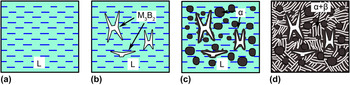
To better understand the microstructure formation mechanism, the schematic of microstructural evolution of WM is illustrated in Fig. 9 and four main stages can be assigned. Reference Askeland and Wright23 At the first stage, the WM is melted by the arc and the liquid WM, i.e. a mixing of Mo2FeB2-based cermets and 316L stainless steel, is formed [Fig. 9(a)]. Afterward, the M3B2 phase generates at a relatively high temperature with consuming a large amount of Mo and B. At the same time, the liquid hypoeutectic Fe–Mo–Cr–Ni alloy is left as shown in Fig. 9(b). It should be noted that the formation of M3B2 phase is inhibited due to the rapid cooling speed in this stage. On reaching the liquidus temperature, solid α (γ-Fe based binder) containing less Mo nucleates in the liquid phase and at the interface of M3B2 phase [Fig. 9(c)]. When the temperature is below the eutectic temperature, all the remaining liquid goes through the eutectic reaction and transforms to a lamellar mixture of α and β (M23B6) as shown in Fig. 9(d). It can be seen the eutectic microconstituent (α + β) is continuous and the primary phase (α) is dispersed between the colonies of the eutectic microsonstituent.
Microstructure formation mechanism of the WM: (a) Formation of liquid WM, (b) nucleation and growth of M3B2 phase, (c) formation of solid α (γ-Fe based binder), (d) generation of eutectic microconstituent (α+β).

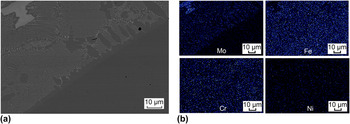
The BSE image of interface between WM and 316L stainless steel is shown in Fig. 6(d). It can be seen that there is a narrow transition zone where little M3B2 phase appears and a large amount of eutectic is formed. The major element distribution in this region is shown in Fig. 10. As can be seen, Mo content in WM is obviously higher than that in 316L stainless steel, with Mo enriched in M3B2 phase significantly. Fe, Ni and Cr are distributed uniformly in WM as well as 316L stainless steel, but Fe is relatively scarce in the M3B2 phase. The interface between WM and 316L stainless steel seems bland due to the similar chemical composition of 316L stainless steel and the γ-Fe based binder, thus its discussion is concise in this paper.
(a) BSE image of the interface of WM and 316L stainless steel, (b) Major elements distribution in corresponding to the BSE image.

D. Microhardness
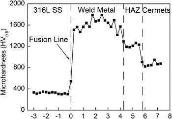
The microhardness distribution of the weld joint is shown in Fig. 11. The graph indicates that microhardness of 316L stainless steel stays nearly constant and keeps a low value. Similarly, the microhardness of Mo2FeB2-based cermets is almost invariable as well, but its value is significantly higher than that of 316L stainless steel, indicating a better wear resistance. In HAZ near Mo2FeB2-based cermets, microhardness increases slightly, which can be explained by the dissolution of M3B2 phase. During the welding process, HAZ adjacent to the fusion line was heated to a high temperature above 1220 °C, leading to the partial dissolution of smaller M3B2 grains and the growth and coalescence of relatively coarse M3B2 grains as discussed above. Afterward, it cooled down rapidly and the Mo and B atoms coming from the dissolution of M3B2 phase formed the solid solution with the γ-Fe based binder, which resulted in the increase of microhardness. WM has the highest microhardness, which may result from the high Mo, Cr, and B content in the γ-Fe based binder as shown in Table III. As is known, Mo and Cr could improve the hardenability of γ-Fe based binder and B could form the solid solution. On the other hand, the M23B6 type boride phase was formed due to the limited solid solubility of B atoms in γ-Fe based binder, which could make a contribution to the microhardness as well. It should be noted that the extremely high microhardness indicates the excessive brittleness of WM, which is detrimental to the mechanical properties of the joint. To decrease the brittleness of WM, much work needs to do in the future. It is supposed that the suitable welding parameters and proper filler metal will reduce the brittleness of WM and thus improve the mechanical properties of the whole joint.
Microhardness distribution of the weld joint.

E. Corrosion behavior
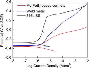
The corrosion behavior of base metal and WM was investigated by potentiodynamic polarization technique in 3.5 wt% NaCl solution. The polarization curves are shown in Fig. 12. As can be seen, there is no significant passivation stage in the Mo2FeB2-based cermets and WM. In other word, they behaved as active metal unlike 316L stainless steel. It is clear from Fig. 12 that the order of corrosion resistance of different samples is: 316L stainless steel > WM > Mo2FeB2-based cermets.
Representative potentiodynamic polarization curves of different samples in 3.5 wt% NaCl solution.

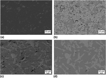
The corrosion behavior of a certain material is usually influenced by many factors, such as chemical composition, microstructure and surface morphologies. Reference Balusamy, Kumar and Sankara Narayanan24–Reference Balusamy, Sankara Narayanan, Ravichandran, Park and Lee27 As is well known, chemical elements such as Cr and Mo have crucial effects on the corrosion resistance and they have been widely used in stainless steel. Cr addition could promote the formation of passive film and increase the corrosion potential. Reference Kotecki and Lippold28,Reference Lee29 Mo addition is able to improve the pitting resistance and crevice corrosion resistance. Reference Kotecki and Lippold28,Reference Lee29 As for Mo2FeB2-based cermets, its corrosion resistance is much poorer than that of 316L stainless steel though it contains substantial Cr and Mo addition. Figure 13(a) and 13(b) show the SEM image and corresponding BSE image of the surface morphologies of Mo2FeB2-based cermets after electrochemical tests respectively. As can be seen, the corrosion is likely to occur at the boundaries between M3B2 grains and γ-Fe based binder and incline to the low Mo content γ-Fe based binder. This can be explained by the high distortion energy at the boundaries between M3B2 phase (tetragonal system Reference Gladyshevskii, Fedorov, Kuz'Ma and Skolozdra30 ) and γ-Fe based binder (austenite phase in cubic system). Compared to the Mo2FeB2-based cermets, WM has a better corrosion resistance because of the relatively homogenous distribution of Mo and the higher Cr content. During the welding process, the fast cooling of WM could inhibit the formation of M3B2 phase and a large number of Mo atoms dissolved into the matrix as discussed above. Besides, Cr atoms from the melted 316L stainless steel could increase the Cr content in this zone, which was also beneficial to the corrosion resistance. The SEM image and corresponding BSE image of surface morphologies of WM after electrochemical tests are shown in Figs. 13(c) and 13(d) respectively. Similar to Mo2FeB2-based cermets, the pits tend to occur at the interface between M3B2 grains and γ-Fe based binder.
Surface morphologies of Mo2FeB2-based cermets and WM after electrochemical tests: (a) image of Mo2FeB2-based cermets in SE mode, (b) image of Mo2FeB2-based cermets in BSE mode, (c) image of WM in SE mode, (d) image of WM in BSE mode.

IV. CONCLUSIONS
In the present work, the weldability between Mo2FeB2-based cermets and 316L stainless steel by GTAW was investigated by PRRC test. TRS was measured by the three-point bending test. Besides, the microstructure, elements distribution, microhardness and corrosion behavior in different zones of the joint was studied. The conclusions can be given as follows:
Weld solidification cracking susceptibility exists in the fusion zone due to the restraint and crack-susceptible microstructure. TRS of WM is greater than that of Mo2FeB2-based cermets, indicating a good bonding strength of the joint.
WM is composed of coarse irregular M3B2 phase and hypoeutectic microstructure. In the hypoeutectic alloy, the eutectic microconstituent (α + β) is continuous and the primary phase (α) is dispersed between the colonies of the eutectic microsonstituent. α and β phase stand for the γ-Fe based binder and M23B6 phase respectively. In the HAZ near Mo2FeB2-based cermets, a small amount of M3B2 boride hard phase dissolves into the γ-Fe based binder, accompanied by the growth and coalescence of other M3B2 grains.
The microhardness of Mo2FeB2-based cermets is significantly higher than that of 316L stainless steel. In HAZ near Mo2FeB2-based cermets, microhardness rises a little due to the increase of Mo and B content in the γ-Fe based binder which is caused by the dissolution of M3B2 phase. WM has the highest microhardness in the whole joint and this is primarily owed to the high content of Mo, B and Cr in the γ-Fe based binder and the formation of M23B6 phase. It should be noted that the high microhardness of WM implies its extreme brittleness, which is a critical issue to settle in the future.
Mo2FeB2-based cermets are easily prone to corrosion in the whole joint. WM has a better corrosion resistance than Mo2FeB2-based cermets, which is mainly attributed to the relatively homogenous distribution of Mo and the higher Cr content in this zone. In Mo2FeB2-based cermets and WM, the corrosion is likely to occur at the boundaries between M3B2 phases and the matrix and incline to the low Mo content γ-Fe based binder.
ACKNOWLEDGMENTS
The authors gratefully acknowledge the support provided by the Natural Science Foundation of Shandong Province (ZR2010EM067) and Innovation Fund for Technology Based Firms (11C26213702324).