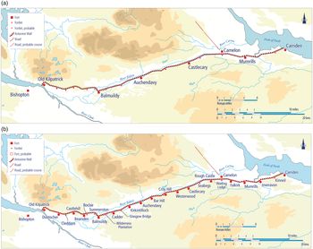


There are currently two models to explain why the distribution of forts along the Antonine Wall is so much closer than that found on most other Roman frontiers (fig. 1).Footnote 1 The first is that it was a coherent, unitary design with garrisons intelligently positioned in a flexible response to local conditions. This view originated in the 1930s, was maintained through the 1960s and has recently been reasserted.Footnote 2 The second, first proposed by John Gillam in the 1970s, is that the original design was broadly based on that of Hadrian's Wall in its more developed form, with forts at a mean interval of 8 Roman miles (11.8 km) and fortlets approximately every 1.1 Roman miles (1.6 km), but that it rapidly underwent major amendment with the addition of a series of more closely spaced and generally smaller secondary forts to replace many of the fortlets.Footnote 3 These two views represent rather different perceptions of the character of Roman frontier design and implementation. The first sees the process as one of careful assessment and detailed advance preparation to determine the potential nature and direction of the local threat and the most appropriate physical response to it. The second, while mindful of the importance of local topography and political geography, assumes a rather more ad hoc approach, adopting and adapting systems that had been tried and tested elsewhere, but with the flexibility to respond to changing circumstances as necessary.
Plans of the Antonine Wall: (a) phase 1 with primary forts and fortlets; (b) phase 2 with the addition of secondary forts. (Both by kind permission of David Breeze)

Gillam's radical hypothesis seemed to be readily capable of being tested in the field by a search for more of his predicted series of fortlets. This challenge was immediately taken up and rapidly resulted in several new discoveries, prompting widespread acceptance of the hypothesis.Footnote 4 The recent challenge to this consensus arises from a reassessment of the strategic positioning of the forts and the apparent primacy of their locations in relation to the planning of the Wall line. In his consideration of Roman military surveying practice, John Poulter notes that the line of the Antonine Wall appears to be curved to run up to, or past, known installations, including several supposedly secondary forts, indicating the possibility that their positions had been marked out before the course of the Wall had been fixed.Footnote 5 Building on this argument, Erik Graafstal and colleagues have drawn attention to the locations of certain forts, including some thought to be secondary, whose topographic positions seemed to have been carefully chosen in order to control potentially clandestine access routes to the Wall from both the north and south.Footnote 6
It is entirely logical that the positions of forts and fortlets planned from the outset should have been influenced by strategic concerns about the control of movement. It also seems likely that these locations would then have determined the line followed by the linear barrier. Indeed, several discussed below can be shown to have preceded its construction. This contrasts with the more formulaic design of Hadrian's Wall, where none of the attached forts were part of the original plan, but were added later, and helps to explain why the Antonine rampart follows a more irregular line than its Hadrianic predecessor.Footnote 7 However, it does not follow that all the forts on the Antonine Wall were, therefore, primary, since some may simply have replaced primary fortlets on or close to the same locations, as Gillam suggests. This is not merely a hypothetical argument, but can now be demonstrated to have occurred in at least three, and probably four, cases
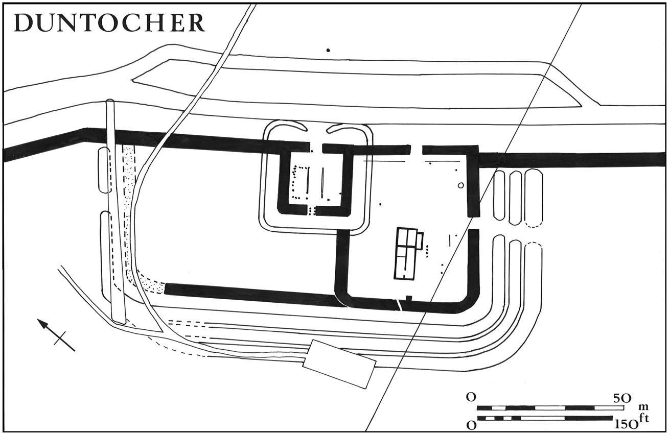
Three sites provide clear and unequivocal archaeological evidence of a major change of plan during the construction of the Antonine Wall. At Duntocher, towards the western end of the Wall, a fortlet was constructed originally as a freestanding structure surrounded by a single ditch (fig. 2).Footnote 8 According to the excavator, it was then replaced by a very small fort with an attached annexe, though there remains some uncertainty about which is which or, indeed, whether the two were originally intended to constitute a single fort enclosure.Footnote 9 Despite the small size of the fort, it was provided with a bath-house by the Duntocher Burn some 100 m to the north-west.Footnote 10 Recent geophysical survey at the site has indicated not only that there were three ditches to the north of the fort, rather than the two recorded during the excavation, but also that a causeway was provided across at least the outer two in front of the gate of the fortlet.Footnote 11 This would seem to suggest that its original northern entrance, which lies approximately in the centre of the whole fort-fortlet-annexe complex, was maintained when the fortlet was subsumed into the layout of fort. Only after this development did the turf rampart reach the site, indicating that this replacement of the fortlet by a fort must have occurred while the construction of the Wall was ongoing. It is important in this context to note that this most westerly sector of the running barrier was the last to be built, as evidenced by the Distance Stones which record the 4 miles (6.4 km) from Castlehill to the Clyde being divided up between the legions into six much smaller sectors, a decision which is most plausibly explained as intended to speed up completion of its construction.Footnote 12
Plan of the Roman fortlet and fort at Duntocher based on the evidence from excavation. (By kind permission of L.J.F. Keppie and the Glasgow Archaeological Society)

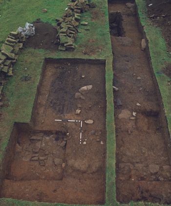
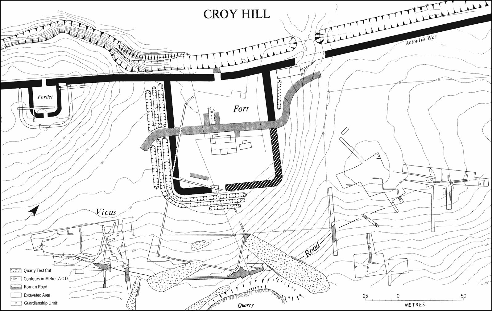
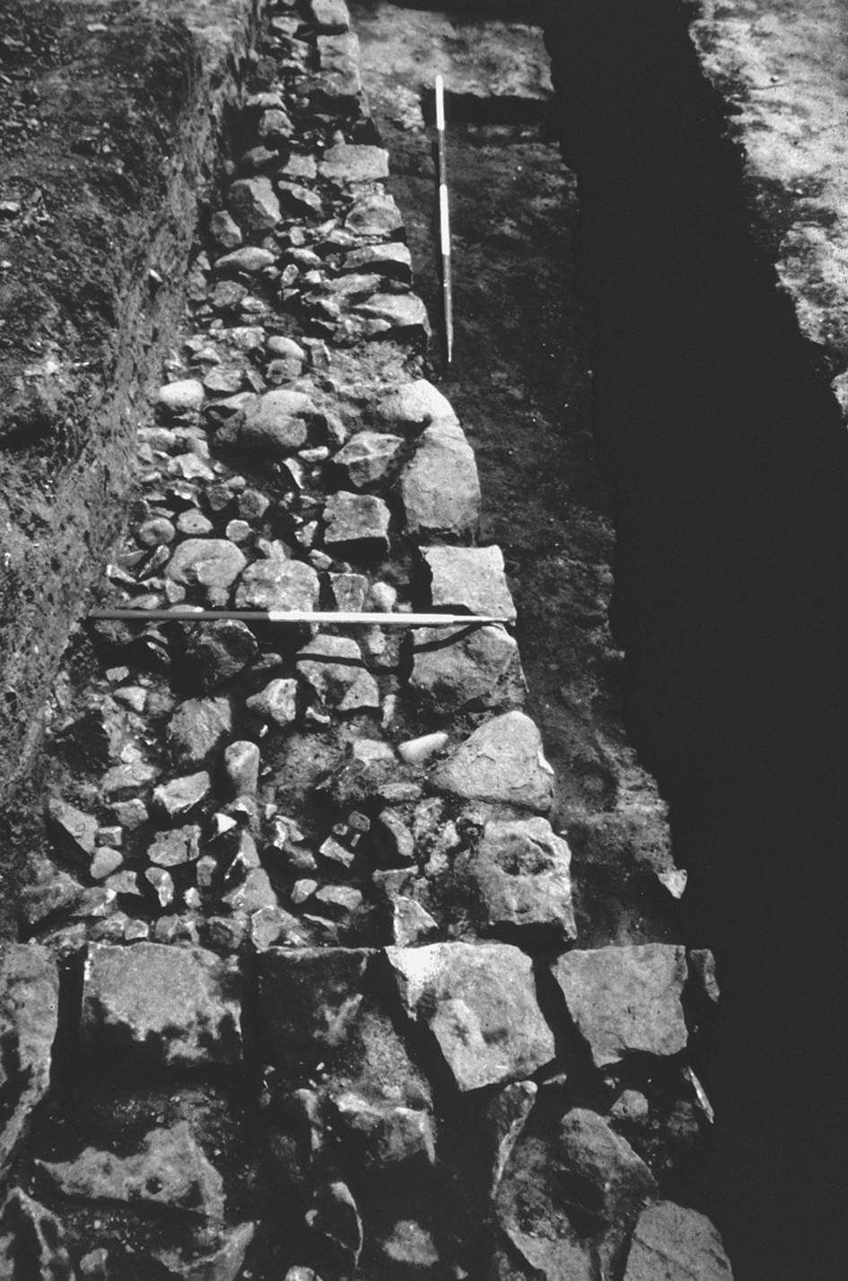
The fortlet discovered on Croy Hill in 1977 was contemporary with the construction of the Wall, as both its rampart base and the turf above it were of one build with the Wall rampart (fig. 3).Footnote 13 Yet a small fort is located only 80 m to its east (fig. 4). This close juxtaposition makes no sense if the two installations were part of the same, original, strategic design, as Graafstal and colleagues were obliged to admit.Footnote 14 That this fort was a secondary addition to the Wall is indicated by a range of evidence. Firstly, it overlies the site of an enclosure of Antonine date that shows signs of occupation over a longer period than would normally be expected for a temporary camp. Not only was the enclosure provided with an internal road, but there had been a considerable build-up of silt in its ditches before the fort was built over them.Footnote 15 The function of this enclosure is not known, but it was presumably associated in some way with the surveying or construction of the Wall.Footnote 16 Secondly, the fort is recorded as being structurally secondary at its north-western corner, where its western rampart abuts the back of the Wall rampart at a higher level.Footnote 17 The fort rampart at the north-eastern corner shows a similar relationship, but coincides here with the location of a stone-lined cistern, presumably capitalising on a natural spring, whose associated overflow outlet underlies, and so must predate, the Wall rampart. However, Sir George Macdonald specifically notes that the north-eastern side of the cistern had been demolished and filled with boulders to serve as the basis for the eastern rampart of the fort, thus confirming the fort's secondary character, even if the chronological associations of the cistern remain uncertain.Footnote 18 It has been postulated that this cistern may relate to the bath-house of an originally planned fort positioned immediately to the east of the known one, centred on the well-known undug causeway across the Wall ditch at this point.Footnote 19 There is, however, no other archaeological evidence for the existence of such a fort, despite quite extensive excavation extending across the supposed position of its southern defences, while its proposed location in an area of lower-lying, damp ground is much less favourable for settlement than the known fort site on the plateau to the west.Footnote 20 The supposed fort causeway is in fact a 25-m wide dolerite surface outcrop whose removal by hand is likely to have been sufficiently daunting to have deterred the legionary builders; this is a problem that they seem to have experienced also to the east of the fort at Bar Hill and near the western end of the Wall at Carleith, as well as around the south-eastern perimeter of the fort at Croy Hill itself.Footnote 21
The intersection of the ramparts of the Antonine Wall (left) and the fortlet at Croy Hill from the west, showing the lower layers of turf and the merging of the kerb stones.

Plan of the fort and fortlet at Croy Hill. (Drawn by Lorraine McEwan)

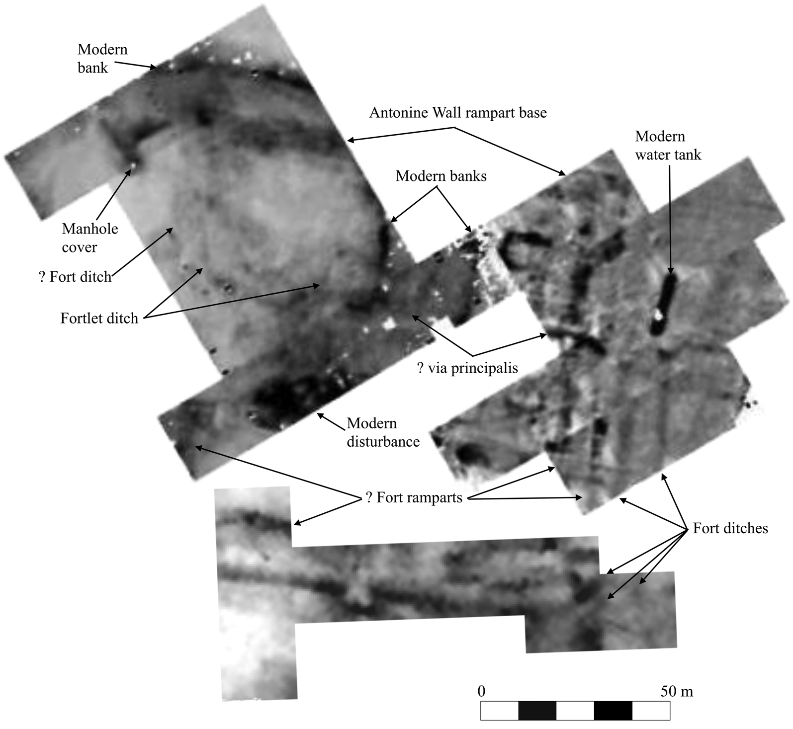
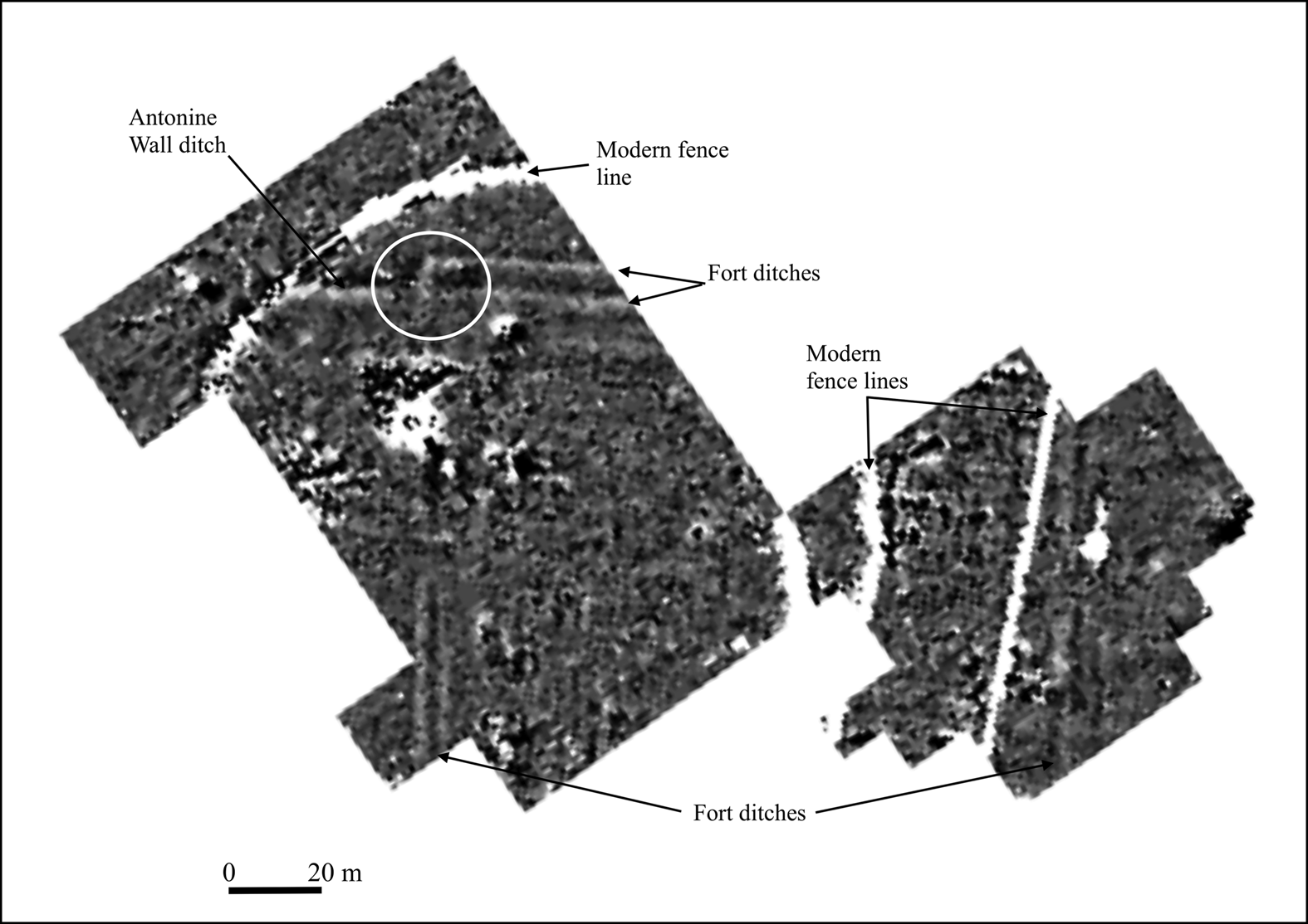
The fort at Castlehill occupies one of the highest positions on the Wall, at a point where the line of the linear barrier changes direction quite sharply. Antiquarian accounts record a small, rectangular, raised plateau on the summit of the hill, situated within a larger enclosure, which is strongly suggestive of a fortlet and fort on the same site.Footnote 22 The latter was confirmed from the air in 1947,Footnote 23 indicating that the fort was not centred on the hill, but extended down its southern and eastern slopes. More recently, resistivity survey has identified a U-shaped, single-ditched enclosure abutting the back of the Wall at the top of the hill in the north-western corner of the fort (fig. 5).Footnote 24 Its dimensions (c. 30–7 m by 35 m) and slightly irregular shape are quite closely paralleled by those of the ditch surrounding the fortlet at Kinneil. Furthermore, magnetometer survey reveals a clear disjuncture in that same corner at the point of intersection between the Wall ditch and the fort ditches (fig. 6), which must indicate that they were not built contemporaneously. The ditch of the latter appears to cut across the line of the former, though it is perhaps more likely that the relationship mirrors the sequence at Duntocher, with the fort replacing the fortlet as a freestanding structure to which the Wall was later abutted.
Annotated resistivity survey plot of the north-western corner of the fort at Castlehill showing the small ditched enclosure. (By kind permission of Richard Jones)

Annotated magnetometer survey plot of the north-western corner of the fort at Castlehill showing the disjuncture (circled) between the ditches of the fort and the Antonine Wall. (By kind permission of Richard Jones)

There is no direct archaeological evidence of a fortlet attached to the Wall at Bar Hill, though attention has been drawn to a possible fortlet-shaped platform behind the Wall in the field immediately to the west of the fort.Footnote 25 Indeed, the existence of such a fortlet to provide a gateway through the Wall would have been an essential strategic requirement; otherwise, the garrison of the adjacent fort, the only one on the Wall line not attached to the running barrier,Footnote 26 would have been cut off from access to the north by the Wall itself. Had such a fortlet not already been in existence, the fort at Bar Hill ought surely to have been attached to the rear of the Wall in order to provide that access. It could be argued that the fort was built first, but had that been the case there would have been nothing to prevent the builders from running the Wall rampart up to its northern corners, as they did at Balmuildy and Castlecary. Furthermore, there is some independent evidence that the fort was a secondary addition to the Wall system as it overlies a small, rectangular enclosure with rounded corners and an annexe on its western side which has produced Antonine pottery from slight features in its interior. Most of the V-shaped ditches of this enclosure had silted up to a considerable depth before the fort was constructed over it, though the ditch on its southern side had been deliberately infilled with turf or, where it passed under stone walls, with rubble.Footnote 27 Given their broad similarities, both in form and occupation history, a function similar to the enclosure beneath the fort at Croy Hill is generally assumed.Footnote 28
It is axiomatic to the Gillam hypothesis that a chain of fortlets was part of the original plan for the Antonine Wall. He suggested originally that they were spaced at intervals that ‘were roughly, though not precisely, regular’, averaging 1.1 Roman miles (1.6 km) apart.Footnote 29 At the time, only four were known (Duntocher, Wilderness Plantation, Glasgow Bridge and Watling Lodge). As more fortlets were discovered (Cleddans, Summerston, Croy Hill, Seabegs Wood and Kinneil),Footnote 30 bringing the total to nine, variations on the distribution scheme were suggested, while still adhering to the basic principle of regular spacing.Footnote 31 Thereafter, the rate of successful discoveries has not continued, despite efforts being sustained for some time, which has led some to cast doubt on the very existence of such a system.Footnote 32 However, one new fortlet has recently come to light as a result of excavation ahead of building development at BoclairFootnote 33 several hundred metres east of the fort at Bearsden, and two others are confidently predicted in this paper at Castlehill and Bar Hill. This would bring the total to 12. Given the fact that the Wall runs through the most densely populated region of Scotland, a potentially 30 per cent recovery rate is not unreasonable. What has become increasingly clear, however, is that postulating the location of fortlets entirely on the basis of a principle of minor variations on a one-Roman-mile spacing system is perhaps overly prescriptive, even if some do still seem to fit that general pattern.Footnote 34
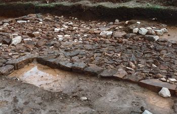
The stratigraphic relationship between the fortlets and the Wall is consistent wherever it has been tested by excavation. All are either earlier than or contemporary with the Wall rampart, indicating that they were part of the original design for the frontier. The examples at Duntocher and Croy Hill have already been noted (figs 2, 3 and 4). Cleddans, like Duntocher, was built as a freestanding structure against which the Wall rampart later abutted.Footnote 35 It is absolutely clear that the kerbs that defined the edges of the ramparts at both Wilderness Plantation and Kinneil continued around the junction between the Wall and fortlet, confirming that they were of one build (fig. 7), despite attempts to cast doubt on this observed relationship.Footnote 36 Finally, the Wall detours northwards from its line at Seabegs Wood in order to take in the site of the fortlet there, which sits on a small plateau. This indicates the primacy of its location in relation to the planning of the Wall, a relationship that is confirmed stratigraphically as the rampart bases of both Wall and fortlet were clearly of one build.Footnote 37
Intersection of the rampart bases of the Antonine Wall (to the left) and the fortlet (to the right) at Kinneil from the south-west, showing their contemporary construction.

There are also strong hints that some of the fortlets changed their function or went out of use quite rapidly, as might be expected if they were superseded by forts nearby. Substantial alterations took place at Kinneil.Footnote 38 The northern gate was dismantled and a hearth constructed over the road, while a secondary layer of cobbling sealed much of the interior, including the barrack buildings. Two lean-to structures at the back of the northern rampart may, however, have continued in use. Similar cobbling has been recorded at Wilderness Plantation, where it also overlay the barrack buildings, though pottery recovered from above it suggests that occupation continued in some form.Footnote 39 The interior of the fortlet at Duntocher was also cobbled over, though in that case, as noted above, the fortlet was superseded by a fort.Footnote 40 Finally, slight traces of apparently secondary cobbling have been recorded within the interior of the fortlets at both Croy Hill and Seabegs Wood, but in neither case were the excavations sufficiently substantial to be certain of its function.Footnote 41 It has been argued that such cobbling may simply have been intended to provide a useful hard surface in damp conditions,Footnote 42 but if this were the case, it is difficult to understand why it was not a more consistent feature at other, larger installations on the Antonine Wall. Moreover, where most fully recorded, the cobbling clearly overlies the remains of barrack buildings.
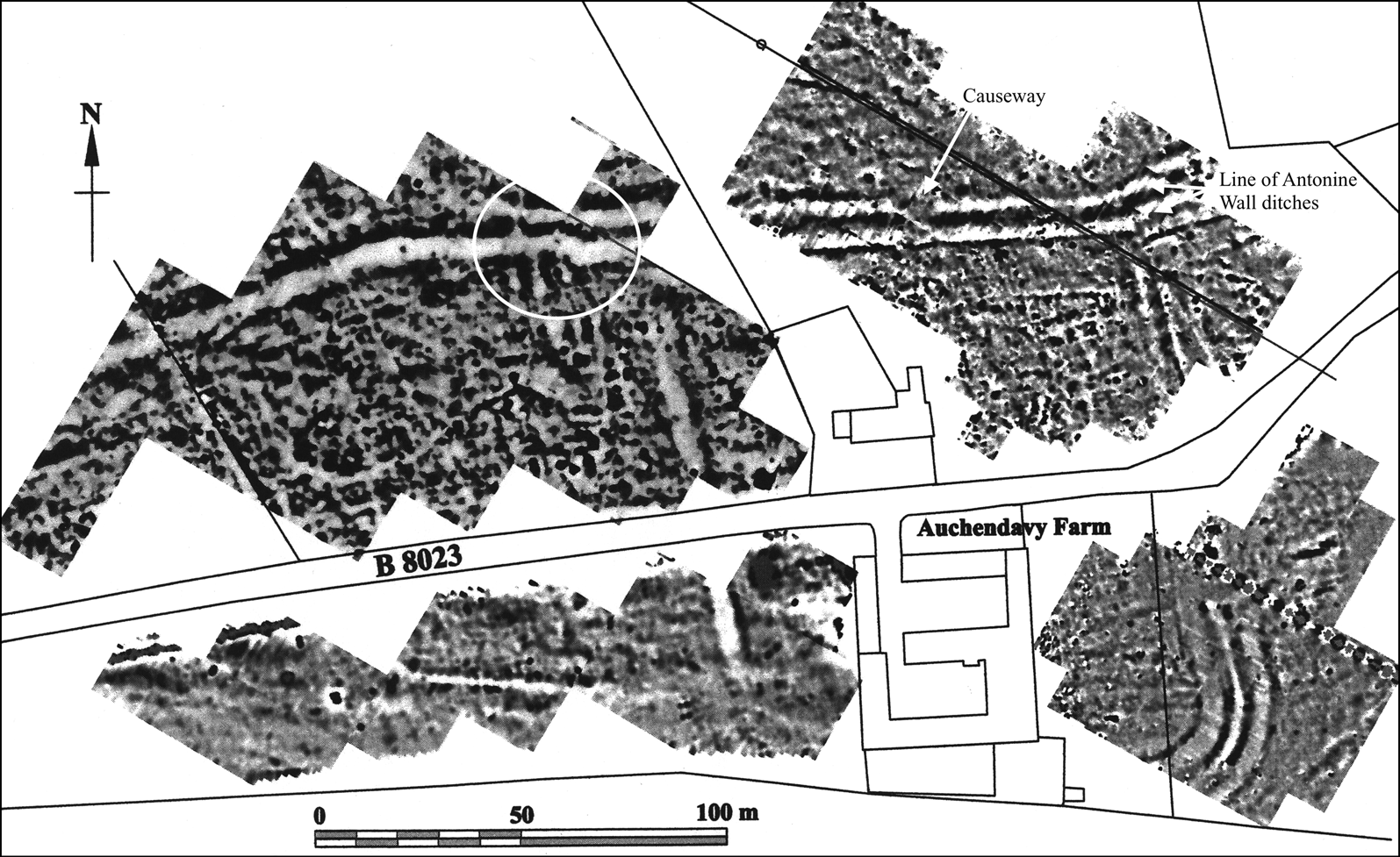
By way of contrast with the fortlets, the stratigraphic relationship between the forts and the Wall is inconsistent. Some forts are clearly earlier than or contemporary with the Wall rampart, suggesting that they too were part of the original design. Duntocher has already been discussed, but is a special case as the small fort on the site post-dates a fortlet (fig. 2) so cannot have been intended as a primary installation. The fort at the western end of the Wall at Old Kilpatrick was originally built as a freestanding enclosure with all four corners rounded, though the layout of its ditches indicates that the arrival of the Wall rampart to abut its northern angle was anticipated.Footnote 43 Balmuildy, one of the only two forts built in stone, clearly preceded the construction of the Wall rampart as its northern corners were squared rather than rounded and were provided with short wing walls to facilitate their integration into the linear barrier that eventually abutted them.Footnote 44 Castlecary, the only other stone fort, was not provided with wing walls, but its northern corners too seem to have been squared in anticipation of them subsequently abutting the Wall rampart, as recent excavation at the north-eastern corner has demonstrated.Footnote 45 That the fort at Mumrills was part of the original design has long been assumed because of the way the Wall markedly changes direction to accommodate the site, creating what have been referred to as wing walls, by analogy with those at Balmuildy. Subsequent examination of the defences, however, has revealed that the rampart on the eastern side of the fort slightly overlapped the rear kerb of the Wall rampart, a relationship usually taken as indicative of secondary construction.Footnote 46 However, the suggestion that there was an earlier fort on the site of the later annexe to the west has little to commend it as it is based on an assertion of two phases in the defences in the north-western corner of the annexe, which has no solid evidential basis.Footnote 47 Finally, geophysical evidence indicates that the fort at Auchendavy was part of the original design of the Wall.Footnote 48 As at Mumrills, the Wall shows marked changes of alignment in order to accommodate the position of the fort. It was also provided with an undug causeway across the ditch at its northern gate and shows hints of a disjuncture with the Antonine Wall ditch outside its north-western corner (fig. 8). Higher-resolution magnetometer survey revealed the disjuncture and a probable wing wall much more clearly, and confirmed that the fort was provided with a second ditch to the north of the Wall. It is perhaps not without significance that those forts that preceded or were contemporary with the construction of the linear barrier are some of the largest known along the line.Footnote 49 They are also spaced some 7.1–9.2 Roman miles (10.5–13.6 km) apart; this is similar to the distances between the forts on Hadrian's Wall, which vary between 6.3 and 9.3 Roman miles apart (9.3–13.8 km).Footnote 50
Annotated magnetometer survey plot of the fort at Auchendavy showing the primary causeway and the disjuncture (circled) between the ditches of the fort and the Antonine Wall by the north-western corner. (By kind permission of Richard Jones)

On the other hand, several forts have produced evidence that they were constructed after the Wall rampart was laid out. Nonetheless, because contradictions in those stratigraphic relationships have been noted at a small number of sites, it has been suggested that such relationships have no relevance to the conceptual planning of the Wall and that the simplest solution is to assume that all forts were primary unless proven otherwise.Footnote 51 It is argued here, however, that these structural relationships are sufficiently consistent to highlight a significant general pattern.
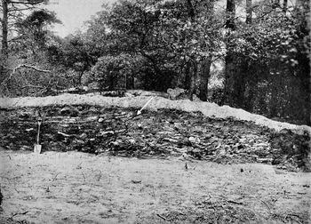
The forts at Croy Hill and Castlehill have already been shown to be secondary (figs 4 and 6). Excavation at the north-western corner of the fort at Westerwood indicates that it too was a later addition, as its rampart base abutted and overlapped the rear of the Wall.Footnote 52 Rescue excavation in 1991 identified a length of cobble foundation abutting the rear of the Wall at Inveravon (fig. 9), whose earthen core was separated from that of the Wall by the unbroken clay cheek of the Wall rampart.Footnote 53 Part of a second such foundation was identified running parallel to the Wall some 34.5 m to the south. The excavators interpret the first foundation as the base of an expansion and the second as the southern rampart of a later small fort. Both foundations may represent sections of rampart defining a small fort, possibly with an annexe, though this interpretation, too, is not without problems.Footnote 54 In either case, however, the fort was clearly a secondary addition to the Wall. At only three sites is the structural relationship between fort and Wall ambiguous. One, Mumrills, has been discussed already. At Cadder the kerbstones at the rear of the Wall continued past the junction with the north-western rampart of the fort, suggesting it was secondary, but a causeway had been provided across the Wall ditch,Footnote 55 which implies that the existence of the fort was already known when the ditch was dug. At Rough Castle the bases of both the eastern and western ramparts of the fort butted against the southern side of the Wall base, suggesting that the laying out of the fort was secondary to that of the Wall.Footnote 56 Much has been made, however, of the apparently contradictory indication that in the north-eastern corner the turf rampart of fort and Wall was of one build. This suggestion is then used to support a wider argument that a secondary rampart base need not be indicative of secondary construction.Footnote 57 The evidence for such an assertion does not stand up to closer scrutiny. It is based entirely on one rather murky photograph from the excavations undertaken in 1903, yet the contemporary structural relationship it purports to show is not replicated in the equivalent photograph of the north-western corner. Here the superstructure of the fort rampart can clearly be seen to abut the rear of the Antonine Wall, indicating that it is a secondary addition (fig. 10). Furthermore, the excavators specifically comment on the difference in size between the turf layers in the ramparts of the fort and the Wall.Footnote 58 One structural inconsistency that does remain is that an original causeway ran across the Wall ditch, which, as at Cadder, implies that the existence of the fort was already known when the ditch was dug.Footnote 59 However, given that we know from the building sequence at Duntocher that the change of plan there took place while the Wall was still under construction, this may simply reflect the fact that the building of the Antonine Wall rampart and ditch was not entirely synchronised. Such a division of labour has long been envisaged to explain the provision of multiple temporary camps at each end of some of the work sectors defined by the Distance Stones.Footnote 60
Junction of the cobble bases of the Antonine Wall rampart (foreground) and the expansion or rampart at Inveravon from the north, showing that the latter was a secondary addition.

Longitudinal section through the western rampart of the fort at Rough Castle in the north-western corner where it abuts the rear of the Antonine Wall (arrowed), looking west (Buchanan et al. Reference Buchanan, Christison and Anderson1905, fig. 12).

There is no direct stratigraphic evidence to elucidate the structural relationship between the Wall and the remaining forts along it. The published plan of the small fort at Falkirk implies that it was built as a freestanding structure and so actually preceded the construction of the Wall, though no excavation has taken place in the relevant areas to allow such a relationship to be established, as the excavator now acknowledges.Footnote 61 The remains of the fort at Kirkintilloch are very poorly preserved under the medieval castle and later town, and so we know only its general position.Footnote 62 Finally, despite extensive excavations at Bearsden that have established a fairly detailed understanding of the layout and history of the site, it has not been possible to determine the structural relationship with the Wall, though the excavator assumes it was secondary.Footnote 63 A case might be made for the fort being primary because of its original large size (3.7 acres; 1.5 ha internally) and its potentially important strategic location helping to guard the Blane gap, but the recent discovery of a fortlet at Boclair, only a few hundred metres away, would seem to make this less likely.
Cumulatively, the stratigraphic evidence discussed above indicates that all the fortlets were part of the original frontier design, along with a small group of forts (Old Kilpatrick, Balmuildy, Auchendavy and Castlecary), to which two others might reasonably be added (Mumrills and Carriden) (fig. 1a). Similarly, there is a further group of forts that are clearly structurally secondary (Duntocher, Castlehill, Croy Hill, Westerwood and Inveravon), to which others might also reasonably be added (Bearsden, Cadder, Bar Hill and Rough Castle) (fig. 1b). Though there are some inconsistencies and ambiguities in the stratigraphic relationships between some forts and the Wall, they are relatively few and insufficiently clear-cut to undermine this overall pattern. Furthermore, it is surely not insignificant that the putatively secondary installations include the five smallest forts on the Wall, two of them commanded by legionary centurions.Footnote 64
The hypothesis that the Antonine Wall was originally planned to look as it does, with forts positioned approximately every 2 miles (3.2 km) along its length, does not fit easily into our wider understanding of the development of Roman frontiers. Firstly, it presents a striking historical discontinuity in terms of the disposition of manpower along linear frontiers, both within Britain and elsewhere in the Empire. The wider spacing between forts on Hadrian's Wall has already been noted. The average spacing between forts along the limes in the Taunus and Wetterau in Upper Germany is c. 9 km (5.6 miles), while the Oldenwald limes, between the rivers Main and Neckar, shows different fort spacing according to the topography.Footnote 65 In the more mountainous northern sector the forts are small (0.6 ha; 1.5 acres) and relatively closely spaced (5–7 km; 3.1–4.3 miles), while in the southern sector running across the plain they are larger (c. 2.1 ha; 5.2 acres) and more widely spaced (c. 15 km; 9.3 miles). The average spacing between forts on the slightly later Outer limes in Upper Germany is c. 13 km (8 miles), though nearer to 11 km (6.8 miles) across western Raetia. Along the limes Transalutanus in Dacia the spacing between forts varies from c. 10 to 25 km (6.2–15.5 miles).Footnote 66 The unusually close spacing of forts on the Antonine Wall is all the more striking as the troops that built it were still making changes to Hadrian's Wall when the reoccupation of Scotland was set in train. Secondly, apart from flying in the face of the stratigraphic evidence noted above, the argument that the Wall saw no major change of design during its construction does not offer any logical explanation or broader strategic context for the creation of one of the most heavily defended frontiers anywhere in the Roman Empire. If the more flexible, innovative approach that the unitary design of the Antonine Wall supposedly reflects was a key change of approach and the culmination of a long process of frontier development,Footnote 67 it seems strange that on the return to Hadrian's Wall we see little sign of those principles being applied.
By contrast, the hypothesis that the Antonine Wall underwent strategic revision and structural change while it was being built better fits the general pattern of frontier development, as it shows both broad continuity and specific amendment of the stage that had been reached on the Hadrianic frontier by that time. It is important here to emphasise that Gillam does not argue, as some have suggested, that the Antonine Wall was ‘a carbon copy’ that was ‘blindly replicating’ Hadrian's Wall, but rather that ‘it resembled in certain respects the second plan for Hadrian's Wall’ and, fundamentally, that it ‘was changed during the period of construction’, as Hadrian's Wall itself had been.Footnote 68 Thus, there are clear examples of design continuity from Hadrian's Wall in the provision of a regular system of fortlets, which mirror the amendments seen in the more flexible topographic positioning of milecastles on the Narrow Wall,Footnote 69 and in the placing of forts directly on the line of the Wall itself. Other lessons had been learnt from the operation of the Hadrianic frontier and various amendments to the Antonine Wall are readily apparent. These include the provision of a Military Way de novo, the absence of a Vallum and, possibly, of a system of towers, and dispensing with the provision of multiple fort gates opening out to the north. This northward projection of the forts on Hadrian's Wall had been something of a knee-jerk reaction to the problems encountered when troops from the Stanegate forts had been obliged to file though milecastle gateways to access the area north of the linear barrier.Footnote 70
The proposal that there was a change of plan during the construction of the Antonine Wall provides a potential historical context and logical explanation for the unusually close spacing of garrison posts, 80 per cent of which are only 1.5–2.4 miles (2.4–3.9 km) apart. It is highly probable that the building of the Wall would have stimulated a hostile local response, perhaps in recognition of the impact on the indigenous population of the insertion of a hard border that would have been highly disruptive to social cohesion and may have split existing social groups. Indeed, a similar response to the building of Hadrian's Wall has also been suggested.Footnote 71 It is difficult to determine the precise boundaries between such indigenous groups, but the locations of places in the geography of Ptolemy attributed to one, the Dumnonii, suggest that their territory extended across the line of the Wall.Footnote 72 While Fraser Hunter has drawn attention to substantive differences in regional metal-working traditions in the late pre-Roman Iron Age between northern and southern Scotland,Footnote 73 there is no reason to assume that the Forth-Clyde isthmus itself was the dividing line between them. Indeed, the overlap in the distribution of what he terms ‘massive metalwork’ and ‘central British metalwork’ hints at a contested zone between that isthmus and the estuary of the Tay that chimes well with the location of Roman outposts beyond the Antonine Wall.
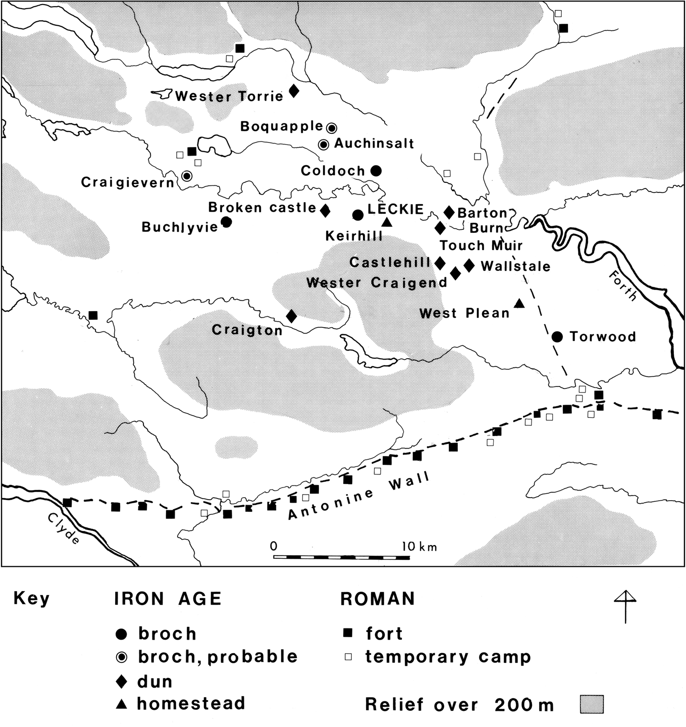
There is also potential archaeological support for the suggestion that there was local unrest at this time. Excavations at Leckie in the Forth valley to the north of the Wall (fig. 11) indicate that the broch there had been destroyed in a major conflagration in the Antonine period. The presence in the destruction deposits of a probable Roman ballista bolt supports the suggestion that the Roman army was responsible.Footnote 74 Yet judging by the recovery of quantities of Samian, glass and other Roman artefacts from the site, this high-status settlement had been in friendly contact with Rome both throughout the Flavian occupation of Scotland and, at least briefly, into the Antonine period. A similar relationship is apparent from the material culture recorded from several other lowland brochs, leading to the interpretation of them as centres of regional élites controlling the importation of prestige goods.Footnote 75
Location map of the broch at Leckie in relation to other Iron Age sites and to the Antonine Wall. (Drawn by Alan Braby and reproduced by kind permission of Euan MacKie)

Destruction of such a local power base would be precisely the response one might expect from the Roman authorities to a local rebellion. The potential impact of such an insurrection on the construction of the Antonine Wall would have been twofold and is visible in the archaeological record. Firstly, it would have caused a delay in the building process while troops dealt with the immediate problem. Secondly, it is likely to have stimulated a desire to increase local security along the linear barrier by dispersing the troops more widely along its length, resulting in the provision of forts spaced more closely together, many of which were small to minimise the concomitant increase in manpower involved. This, in turn, would have caused a further delay to the overall construction programme, which is reflected in the division of the final 4 miles (6.4 km) of the Wall into shorter legionary sectors in order to speed up its completion.
This paper has attempted a re-examination of the Gillam hypothesis concerning the original design of, and subsequent changes to, the layout of the Antonine Wall in response to recent challenges to the validity of his main thesis. This has involved a detailed critique of some of the data from early excavations on the Wall, challenging a number of misconceptions about structural relationships recorded therein, most notably in relation to the forts at Rough Castle and Croy Hill. It has also presented a range of important new or previously unpublished information, particularly from the author's own excavations at Croy Hill and from geophysical surveys at Auchendavy, Duntocher and Castlehill,Footnote 76 which helps to shed further light on the debate. This overall analysis has resulted in a strong reaffirmation of the general principles of the Gillam hypothesis. Finally, it has for the first time offered, and provided potential supporting archaeological evidence for, a possible historical explanation for the changes that resulted in the creation of one of the most intensively garrisoned frontiers in the Roman Empire.
ACKNOWLEDGEMENTS
I am grateful to Lesley Macinnes and L.J.F. Keppie, for their comments on an earlier draft of this paper, to Richard Jones, for allowing me to make use of his unpublished geophysical surveys, and to Simon James, for his comments on the identification of the ballista bolt from Leckie.