Introduction
With the rapid development of the 5G wireless network, a high data rate nearing 1 Gb/s is required to support wireless access applications such as smart cities and smart homes [Reference Yu, Yang, Chen, Wang, Li, Li and Wang1]. It has been confirmed that ultra-wideband (UWB) technology combined with multiple-input multiple-output (MIMO) is an effective solution for these applications [Reference Kaiser, Zheng and Dimitrov2]. UWB system has the advantages of high transmission rate, great capability, and low power consumption, but the signal quality is lowered due to the multipath fading effect. Fortunately, MIMO technology can suppress the multipath fading effect without additional power and bandwidth consumption. Hence, the UWB-MIMO communication system can achieve the goal of high data rate and great capability. As a significant component of the UWB-MIMO system, the antenna has a crucial effect on system performance. To be suitable for the miniaturization and portability of devices, antennas must be designed in small size, which presents a great challenge for designers to achieve large isolation between MIMO antenna elements. Besides, the UWB spectrum that the Federal Communications Commission (FCC) assigned has overlapped with that of some narrowband wireless communications, including Global System for microwave access (WiMAX 3.5 GHz), Wireless Local Area Network (WLAN 5.2/5.8 GHz), X-band satellite communication system (X-band 7/8 GHz), etc. [3]. The band-notched characteristic is required to suppress the interference from these narrowband communications.
Until now, various decoupling methods have been reported, including introducing defective ground structure [Reference Wang, Du, Yang, Ma, Zhao and Cui4–Reference Chattha, Latif, Tahir, Khan and Yang6], adding neutralization line [Reference Zhang and Pedersen7, Reference Li, Chu, Li and Xia8], polarization diversity technique [Reference Yang and Zhou9–Reference Yin, Chen, Chang, Li and Khamas14], adding parasitic strip or stub [Reference Iqbal, Saraereh, Ahmad and Bashir15–Reference Liu, Cheung and Yuk17], using electromagnetic bandgap (EBG) structure [Reference Kumar and Kiran18–Reference Dabasa, Gangwarb, Kanaujiac and Gautamd20], and using metamaterial structure [Reference Sakli, Abdelhamid, Essidand and Sakli21]. In [Reference Wang, Du, Yang, Ma, Zhao and Cui4], the fence-type decoupling structure was etched on the ground, which increased the path of the coupling current and increased the isolation between two radiating elements to 25 dB. In [Reference Zhang and Pedersen7], a metal circular disc was introduced between two elements as a current neutralization line that can neutralize the coupling current, and isolation of higher than 22 dB was realized. In [Reference Li, Chu, Li and Xia8], two protruded ground parts were connected by a compact metal strip to reduce the mutual coupling for the band of 3.0–4.0 GHz, which produced isolation of higher than 20 dB. In [Reference Yang and Zhou9], a decoupling structure composed of a circular patch and four L-shaped branches placed counterclockwise was printed in the center of the four radiating elements and the isolation reached to 15 dB. In [Reference Gómez-Villanueva and Jardón-Aguilar10], four semi-elliptical monopole antennas were placed orthogonally, and isolation of 17 dB was obtained by etching several slits in the ground plane. In [Reference Srivastava and Mohan11], antenna elements were placed asymmetrically, and isolation of 22 dB was achieved. In [Reference Iqbal, Saraereh, Ahmad and Bashir15], F-shaped stubs were extended from the ground plane, which produced isolation higher than 20 dB. In [Reference Kumar and Kiran18], an EBG structure in a meander-line shape was proposed, which improved the isolation to 17 dB. In [Reference Sakli, Abdelhamid, Essidand and Sakli21], by adding metamaterial composed of novel split-ring resonators (SRRs) between radiating elements, the isolation reached 20 dB in a wide bandwidth.
Also, many different techniques are reported to introduce the notched band. In [Reference Chen, Zhou and Hong13], C-shaped and L-shaped slits were etched on the patches, which generated WiMAX and WLAN notched bands. EBG structure was placed around the feed line, which generated X-band notched band. In [Reference Tripathi, Mohan and Yadav16], a C-shaped slot was etched on the patches, which generated a WLAN notched band. In [Reference Liu, Cheung and Yuk17], long rectangular strips were extended from the ground to generate a WLAN notched band.
In addition, the quasi-self-complementary (QSC) structure is also reported as a good candidate for UWB-MIMO design due to its compact size and wide bandwidth [Reference Liu, Wang, Yin, Ren and Wu22–Reference Gorai, Dasgupta and Ghatak25]. In [Reference Liu, Wang, Yin, Ren and Wu22], a UWB MIMO antenna composed of QSC elements oppositely oriented was proposed. A bandwidth of 2.19–11.07 GHz (except 2.86–3.28 GHz) and isolation of higher than 20 dB at most of the band were obtained without extra decoupling methods. In [Reference Zhu, Li, Feng, Deng and Yin23], a UWB MIMO antenna consisting of QSC elements arranged orthogonally was proposed. Also, a bandwidth of 3–12 GHz with a WLAN notched band and isolation of better than 20 dB at most of the band are obtained without additional decoupling structure. The two reports mentioned above provided good candidates for UWB applications and verified the excellent performance of the QSC antenna. However, it is worth noting that the isolation at some frequencies needs further improvement, and the size can be further scaled down. The simultaneous improvement of performances such as miniaturization, high isolation, and multi-notch characteristics is still a challenge for the current UWB MIMO antenna design.
This paper proposes a four-element QSC UWB MIMO antenna with three notched bands. Coplanar waveguide (CPW) feeding combined with QSC structure realizes small size and wideband. By placing the QSC elements orthogonally and adding four regular hexagonal split rings on the back of the substrate, isolation of higher than 22 dB in the band of 3–18 GHz is achieved. Additionally, the double-fork-shaped slit is etched in each radiating element, generating three notched bands covering 3.63–4.24, 5.15–5.98 and 7.17–8 GHz. The antenna design process, and simulated and measured results are described in detail below.
Antenna configuration and design methodology
Antenna element
Figure 1(a) illustrates the structure of the proposed QSC UWB antenna element, Ant_a, in a compact size of 20 × 15 mm2 (0.2λg × 0.15λg), λg is the free-space wavelength over the lowest resonant frequency. The inexpensive dielectric FR4 (thickness hs = 1 mm, dielectric constant ɛr = 4.4) is used as the antenna substrate. A symmetrically regular hexagon cut in half and an enlarged complementary cut ground plane compose the QSC UWB monopole. CPW feeding is applied, resulting in a smaller size and unoccupied backside. The dimensions of Ant_a are given in Table 1. Generally, the input impedance of the QSC element is frequency independent, and thus it has a wideband impedance matching. Figure 2 plots |S 11| of Ant_a varying with frequency. It can be seen that |S 11| < −10 dB at the frequencies from 2.74 to 11.11 GHz, while after 11.11 GHz |S 11| fluctuates around −10 dB. To resolve the fluctuation, the rectangular slot at the CPW feed port is changed into the stepped slot, as shown in Ant_b in Fig. 1(b). |S 11| of Ant_b is also plotted in Fig. 2, and one can notice that the bandwidth of Ant_b is 2.76–18 GHz. The simulations were computed by using the software Ansoft HFSS (https://www.ansys.com/zh-cn/products/electronics/ansys-hfss). Adaptive mesh method was used and the mesh size was set to 5. The solution converges when ΔS (the difference between the S parameters calculated by the current iteration and the previous) is less than 0.02.
The evolution of the proposed QSC UWB element: (a) Ant_a, (b) Ant_b.

|S 11| of the Ant_a and Ant_b.

Optimized dimensions of the proposed four-element QSC UWB-MIMO antenna

Four-element QSC UWB MIMO antenna
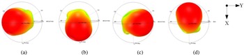
Due to the asymmetry structure of the QSC antenna, it has the characteristic of directional radiation, which indicates that good isolation may be obtained if QSC elements are used to compose a MIMO antenna. Four Ant_b elements are arranged orthogonally to form a four-element QSC UWB MIMO antenna, as depicted in Fig. 3. The optimal parameters are listed in Table 1. Also, the substrate is FR4, and the size is 35 × 35 × 1 mm3 (0.35λg × 0.35λg × 0.01λg). Figure 4 depicts the 3D radiation patterns of the four-element MIMO antenna at 8 GHz. When one port is excited, the others are terminated to matched loads. One can see that the antenna radiates along the −y, +x, +y, and −x-axis when ports 1, 2, 3, and 4 are excited, respectively. The performance of pattern diversity is apparent, which results in high isolation.
Configuration of the four-element QSC UWB MIMO antenna without SRRs.

3D radiation patterns of the four-element QSC MIMO antenna at 8 GHz when (a) port 1, (b) port 2, (c) port 3, and (d) port 4 are excited, respectively.

Figure 5(a) plots the simulated |S 11| of the QSC UWB MIMO antenna (|S 11| without SRRs). One can obtain that the band with |S 11| < −10 dB covers the 3–18 GHz frequency range. Meanwhile, Fig. 5(b) plots the simulated |S 21|, |S 31|, and |S 41| of the antenna (|S 21|&|S 31|&|S 41| without SRRs). In most frequency bands, the isolation of larger than 20 dB is achieved without an additional decoupling structure. Besides, it is worth noting that |S 21| and |S 41| are larger than −20 dB at frequencies from 11.2 to 13.8 GHz.
S-parameters of the QSC MIMO antenna: (a) |S 11| with or without SRRs and (b) |S 21|, |S 31|, and |S 41| with or without SRRs.

Four regular hexagonal SRRs are added to the back of the substrate, as plotted in Fig. 6, aiming to reduce the coupling between the adjacent ports. The optimal parameters of the SRRs are given in Table 2. The four SRRs are arranged orthogonally between adjacent radiating elements. The opening directions of the SRRs from port 1 to port 4 are along the −x, −y, +x, and +y-axis, respectively. For comparison, S-parameters of the antenna with SRRs are also plotted in Fig. 5. One can obtain from Fig. 5(a) that the impedance bandwidth remains at 3–18 GHz. Additionally, one can observe from Fig. 5(b) that |S 21| and |S 41| at the frequency range of 11.2–13.8 GHz reduced to −21 dB after adding the SRRs.
Structure of the QSC UWB MIMO antenna with SRRs.

Dimensions of the SRR

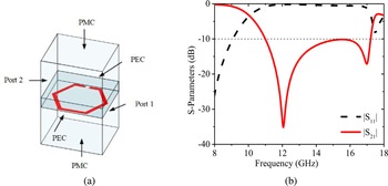
To explore the coupling suppression mechanism of the SRR, S-parameters are simulated using HFSS. The setting of boundaries and ports are depicted in Fig. 7(a). An SRR is printed on the same substrate as the antenna mentioned above, surrounded by an air box with a radiation boundary. The boundary condition of perfect electric is set to the front and back faces. The left and right faces are assigned two wave ports. Figure 7(b) plots |S 11| and |S 21| of the SRR varying with frequency. One can obtain that two resonances occur for the SRR unit cell at 12 and 17 GHz, |S 11| is close to 0 dB from 11 to 17.3 GHz and |S 21| is below −10 dB. Figure 8 plots the SRR unit's surface current distribution at 12 and 17 GHz. It is observed that the lengths of the current concentrated distribution are 6.8 and 4.5 mm respectively, which are nearly 1/2 wavelength at 12 and 17 GHz.
The simulation setup of a hexagonal SRR and S-parameters of the SRR. (a) The simulation setup, (b) S-parameters.

The surface current distribution of the SRR unit at 12 and 17 GHz. (a) 12 GHz, (b) 17 GHz.

Additionally, the permittivity and permeability are calculated based on the values of S-parameters, and their curves are shown in Fig. 9. It is clear that the real part of permittivity is negative from 10 to 15 GHz, and the real part of permeability is negative at 17 GHz. As we know, the propagation of energy will be attenuated in a single negative medium. Therefore, a stopband is formed, which is beneficial to weaken the surface wave propagating between antennas and reduce the mutual coupling.
The (a) permittivity and (b) permeability of the SRR.

Additionally, parameter analysis has been conducted. It has been found that the distance between the center and the outer boundary of the ring, d 3, has the most significant impact on the resonant frequency. A larger value of d 3 means a longer length of the ring. Figure 10 illustrates |S 11| and |S 21| of the SRR when d 3 increases from 1.9 to 2.1 mm. As d 3 increases, the frequency corresponding to the minimum of |S 21| decreases. When d 3 is 2 mm, the stopband is the widest, from 11 to 17.3 GHz, and is suitable for decoupling at frequencies from 11.2 to 13.8 GHz.
|S 11| and |S 21| for different values of d 3.

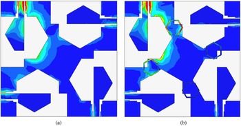
To verify the coupling current suppression effect of the SRRs, Fig. 11 gives the surface current distribution with and without SRRs at 12.1 GHz. Port 1 is excited while the others are terminated with matched loads. It is observed that the amounts of surface currents presented at ports 2 and 4 are significantly reduced if the SRRs are placed.
Distribution of surface current at 12.1 GHz when port 1 is excited: (a) without SRRs and (b) with SRRs.

QSC UWB MIMO antenna with triple band-notched characteristics
In order to suppress the interference of narrowband wireless communications, the double-fork-shaped slit is etched in each radiating element to obtain three notched bands, as illustrated in Fig. 12. The slit consists of an inverted U-shaped slit with a width of 0.2 mm and a meander slit with a width of 0.4 mm connected by a short Z-shaped slit. The optimal parameters of the double-fork-shaped slit are given in Table 3. Figure 13 depicts the triple-notch characteristics of the antenna. The bandwidth with |S 11 < −10 dB| is 2.6–18 GHz. Besides, the antenna generates notched bands covering partial C-band (3.73–4.2 GHz), WLAN (4.93–5.85 GHz), and partial X-band (7–7.76 GHz).
The structure of the triple band-notched QSC UWB MIMO antenna.

Simulated S-parameters of the QSC UWB MIMO antenna with three notched bands.

Geometric dimensions of the double-fork-shaped slit

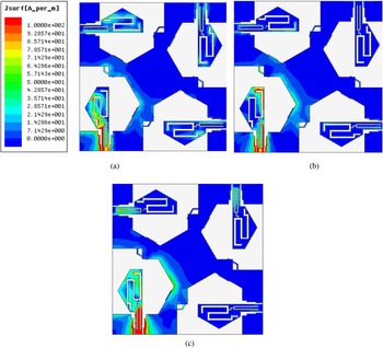
To demonstrate the mechanism of notched bands, the surface current distributions at the notched frequencies of 4, 5.5, and 7.5 GHz are illustrated in Fig. 14. In the simulation, one port is excited, and others are terminated with 50 Ohm loads. One can observe that the surface currents mainly concentrate on the left half, the right half, and the inverted U-shaped slit of the double-fork-shaped slit at 4, 5.5, and 7.5 GHz, respectively. It is worth mentioning that the lengths of the left, right, and the inverted U-shaped slit are 22.1, 16.1, and 11.9 mm, respectively, which are nearly 1/2 wavelength at 4, 5.5, and 7.5 GHz. These slits are equivalent to 1/2 wavelength filters, resulting in three notched bands.
Surface current distributions at frequencies of: (a) 4 GHz, (b) 5.5 GHz, and (c) 7.5 GHz.

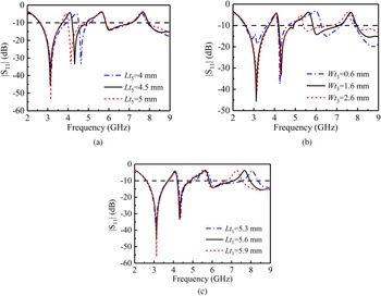
Furthermore, to explore the tunability of the three notch band frequencies, parameter analysis is carried out, and the results are plotted in Fig. 15. Figure 15(a) displays the variation of |S 11| with different values of Lt 5. As Lt 5 increases, the lowest notched central frequency decreases gradually, while the other two notched frequencies remain unchanged. Similarly, as Wt 3 increases, the middle notched central frequency decreases in Fig. 15(b), and as Lt 1 increases the highest notched central frequency decreases in Fig. 15(c). Therefore, the notched performances of the designed antenna are mainly determined by the left, right, and the inverted U-shaped slit length of the double-fork-shaped slit, respectively, and the frequencies can be tuned independently.
|S 11| when values of (a) Lt 5, (b) Wt 3, (c) Lt 1 are different.

Results and discussions
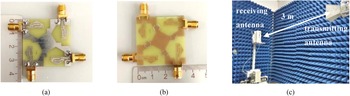
Figure 16 gives the photographs of the fabricated antenna and far-field measurement environment. S-parameters are measured using the Agilent N5222A vector network analyzer, and the radiation patterns are measured using Lab-Volt 8092 training system. As the four radiating elements are center-symmetric, port 1 is excited as an example in the following analysis.
Photographs of antenna and test environment: (a) top view, (b) bottom view, and (c) test environment.

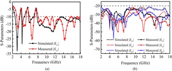
Figure 17 depicts the S-parameters of the proposed QSC UWB MIMO. One can see that the antenna exhibits a wide frequency band of 3–18 GHz (|S 11| < −10 dB) with three notched bands covering 3.63–4.24, 5.15–5.98, and 7.17–8 GHz. Besides, the measured isolations are higher than 22 dB. The deviations between the simulation and experiment results are slight, mainly due to the accumulation of fabrication error and accuracy of substrate dielectric constant.
The simulated and measured (a) |S 11| and (b) |S 21|, |S 31|, and |S 41| of the proposed antenna with three notched bands.

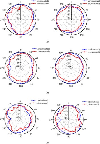
Additionally, Fig. 18 illustrates the simulated and measured radiation patterns at 3.5, 8, and 13.5 GHz in the xz- and yz-planes. The radiation patterns are directional in the yz-plane at 3.5 and 8 GHz. However, due to high-order mode influence at high frequency, there is slight distortion at 13.5 GHz.
Simulated and measured 2D radiation patterns in the xz- and yz-planes. (a) 3.5 GHz, (b) 8 GHz, (c) 13.5 GHz.

Moreover, Fig. 19 depicts the proposed antenna's peak gain and radiation efficiency. One can observe that the simulated and measured peak gain rise from 4.11 to 6.7 dB and 3.11 to 7.5 dB at the operating frequency range respectively, and the radiation efficiency remains above 80%, indicating that the antenna has excellent radiation performance. Moreover, the peak gain and efficiency decrease sharply at the notched bands, indicating that the proposed antenna can suppress narrowband interference very well.
Peak gain and simulated radiation efficiency of the proposed antenna.

In order to validate the diversity performance, the envelope correlation coefficient (ECC), the diversity gain (DG), the total active reflection coefficient (TARC), and the channel capacity loss (CCL) are calculated. The ideal values of ECC, CCL, and TARC are less than 0.5, 0.5 bits/s/Hz, and 0 dB, and that of DG is larger than 6 dB [Reference Choukiker, Sharma and Behera26].
ECCs are calculated as follows [Reference Blanch, Romeu and Corbella27]:

where* denotes complex conjugate. Figure 20(a) depicts the calculated result. One can see that it is less than 0.005. DG value of above 6 dB is within a suitable level [Reference Iqbal, Saraereh, Ahmad and Bashir15]. The DG can be calculated using ECC by [Reference Yang and Zhou9]:

(a) ECCs and (b) DGs of the antenna.

The result is shown in Fig. 20(b), and it is close to 10 dB in the operating band, implying a good performance. Additionally, the antenna's TARC is calculated using S-parameters according to the formula [Reference Yang and Zhou9]:

The result is illustrated in Fig. 21(a). At the operating frequencies the TARC is less than −10 dB. The CCL of both adjacent antenna elements and diagonal elements are calculated using the formulas below [Reference Ahmad, Khan, Manzoor, Soruri, Alibakhshikenari, Dalarsson and Falcone28]:


where “a” is the correlation matrix and i,j = 1,2. The result is plotted in Fig. 21(b). Both CCLs are less than 0.3 bits/s/Hz at frequencies except notched bands.
(a) TARC and (b) CCL of the antenna.

To discuss the novelty, several previously reported four-element UWB MIMO antennas are compared with this work in Table 4. It can be noticed that the proposed antenna is slightly larger than that in [Reference Chen, Zhou and Hong13] and [Reference Tripathi, Mohan and Yadav16], while the isolation is the highest in the list. Simultaneously, the comprehensive performance of the proposed antenna, including bandwidth, notched bands, and peak gain, is the best.
Comparisons between the proposed antenna and other works

Conclusion
A compact four-element QSC UWB MIMO antenna with three notched bands is proposed in this paper. The size of the antenna is 35 × 35 mm2. CPW fed QSC element is designed to obtain smaller size and a wideband (3–18 GHz). Additionally, placing the QSC elements orthogonally and print four regular hexagonal split rings with single negative properties on the other side of the substrate, high isolation (|S 21|&|S 41|&|S 31| < −22 dB) in the entire operating frequency is achieved. Furthermore, to suppress narrowband communication interference, double-fork-shaped slit generates three notched bands in frequency ranges of 3.63–4.24, 5.15–5.98, and 7.17–8 GHz. Besides, the performance of the MIMO antenna system is evaluated by ECC (<0.005), DG (≈10 dB), TARC (lower than −10 dB), and CCL (<0.3 bits/s/Hz). Finally, the simulated and measured results agree well, confirming the antenna's suitability for modern portable UWB applications.
Acknowledgements
This work was supported by the National Natural Science Foundation of China under Grant 62071282 and the Natural Science Foundation of Shanxi province under Grant 202203021211295.
Conflict of interest
None.
 Jinrong Su was born in 1981. She received the B.S. and M.S. degrees in electronic engineering and the Ph.D. degree in radio physics from Shanxi University, Taiyun, China, in 2004, 2007, and 2017, respectively. She is currently an Associate Professor with the Department of Electronics and Information Engineering, Shanxi University. Her research interests include microwave and millimeter-wave integrated circuits and passive device.
 Yanling Li was born in 1996. She received the B.S. degree in communication engineering from Tianjin Normal University, Tianjin, China, in 2019, and the M.S. degree in electronic and communication engineering from Shanxi University, Taiyuan, China, in 2022. Her research interests include ultra-wideband antenna.
 Xinwei Chen received the B.S. and Ph.D. degrees in electronic engineering from Shanxi University, Taiyuan, China, in 2002 and 2013, respectively. He is currently an Associate Professor with the School of Physics and Electronic Engineering, Shanxi University. His research interests include microwave and millimeter-wave passive device.
 Guorui Han was born in Taiyuan, Shanxi, China, in 1977. He received the B.S. and M.S. degrees from Peking University, Beijing, China, in 2000 and 2004, respectively, and the Ph.D. degree from the College of Physics and Electronic Engineering, Shanxi University, Taiyuan, in 2013. His research interests include microwave integrated circuits and MIMO antenna.
 Wenmei Zhang was born in 1969. She received the B.S. and M.S. degrees in radio technology and electromagnetic field and microwave technology from the Nanjing University of Science and Technology, Nanjing, China, in 1992 and 1995, respectively, and the Ph.D. degree in electronic engineering from Shanghai Jiao Tong University, Shanghai, China, in 2004. In 2008 and 2010, she was a Senior Visiting Scholar with the Nanyang University of Technology, Singapore. She holds six Chinese patents, has authored more than 150 papers in peer-reviewed journals, more than 30 papers in conference proceedings. She is currently a Professor with the School of Physics and Electronics, Shanxi University, Taiyuan, China. Her current research interests include microwave/millimeter-wave integrated circuits, EMC, and microstrip antenna. Prof. Zhang served as the General Chair of “2019 Cross Strait Quad-Regional Radio Science and Wireless Technology Conference” and TPC member for multiple conferences.