1. Introduction
The ability to precisely manipulate particles suspended in a fluid is crucial for many processes in fields such as physics, engineering, chemistry and biomedicine. Various techniques, such as optical, magnetic, electric and acoustic tweezers (Dienerowitz, Mazilu & Dholakia Reference Dienerowitz, Mazilu and Dholakia2008; Baudoin & Thomas Reference Baudoin and Thomas2020; De Vlaminck & Dekker Reference De Vlaminck and Dekker2012; Fan et al. Reference Fan, Zhu, Cammarata and Chien2011) have emerged for efficient particle manipulations. Specifically, acoustic tweezing using microscale acoustofluidics has gained increasing attention in recent years (Rufo et al. Reference Rufo, Cai, Friend, Wiklund and Huang2022). It is important to understand the underlying physics of microscale acoustofluidics before applying it to specific acoustic tweezing applications, such as patterning, focusing, sorting, trapping and shaking. Among the various physical effects involved in acoustic microfluidics, acoustic streaming is a well-established and widespread phenomenon in the fields of acoustics, ultrasonics and fluid dynamics.
As early as 1787, Chladni (Reference Chladni1787) observed that fine particles on a vibrating plate can be collected at the antinodes of vibration. Faraday (Reference Faraday1831) found that this phenomenon was caused by vibration-induced air currents, called acoustic streaming, in the vicinity of the plate. Rayleigh (Reference Rayleigh1884) presented the first comprehensive solution for boundary-driven acoustic streaming generated in a standing wave between two infinite parallel plates in 1884. His solution describes the acoustic streaming outside the viscous boundary layer, which is referred to as ‘outer streaming’ or ‘Rayleigh streaming’. Schlichting (Reference Schlichting1932) analysed the acoustic streaming inside the viscous boundary layer (i.e. inner streaming). Rayleigh streaming can be modelled by a slip velocity at the edge of the inner streaming. Nyborg (Reference Nyborg1958) developed a generalised slip velocity solution, which was modified by Lee & Wang (Reference Lee and Wang1989). In recent decades, the slip velocity approach, also known as the limiting velocity method, has been extended to analyse outer streaming fields in specific scenarios, such as circular (Lei et al. Reference Lei, Cheng and Li2020a ) and triangular (Lei et al. Reference Lei, Zheng, Cheng, Li and Huang2024) channels.
In an acoustic microfluidic device, a spherical particle with a radius of
 $r_{p}$
suspended in a dilute aqueous solution is influenced by two main forces: the acoustic radiation force and the acoustic streaming-induced drag force. In a standing wave field, the former force scales with
 $r_{p}^{3}$
and tends to trap particles at pressure nodes or antinodes, while the latter scales with
 $r_{p}$
and drives particles into streamlines. Consequently, although acoustic streaming can be useful in certain situations, it often occurs when unwanted and places a lower limit on the particle size (denoted as
 $r_{p}^{\textit{min}}$
) that the acoustic radiation force can manipulate (Bruus Reference Bruus2012). In resonating acoustic microfluidic devices operating at sub- or low-MHz frequencies,
 $r_{p}^{\textit{min}}$
is typically greater than 0.5
 $\unicode {x03BC}$
m for particles in dilute aqueous solutions. Several works have demonstrated that the cutoff particle diameter can be reduced to the submicron region by increasing the driving frequency and/or combining it with an external factor such as an electric field (Tayebi et al. Reference Tayebi, Yang, Collins and Ai2021; Gao et al. Reference Gao, Liu, Lakerveld and Ding2022). However, acoustic streaming has been shown to be capable of concentrating nanoparticles or assisting the acoustic radiation force to focus particles at the centre of streaming vortices. This phenomenon has been observed in various scenarios, such as nanoparticle focusing in single streaming vortices generated by bulk acoustic waves in square silicon chips (Antfolk et al. Reference Antfolk, Muller, Augustsson, Bruus and Laurell2014; Tsuyama et al. Reference Tsuyama2023; Ugawa et al. Reference Ugawa2022) or a virtual microchannel (Yang et al. Reference Yang2022), and surface acoustic waves in a glass capillary (Mao et al. Reference Mao, Li, Wu, Bachman, Mesyngier, Guo, Liu, Costanzo and Huang2017), polydimethylsiloxane channel (Collins et al. Reference Collins, Ma, Han and Ai2016) or centrifugal droplet (Gu et al. Reference Gu2021).
However, there has been limited research demonstrating the suppression of acoustic streaming velocities for acoustophoretic patterning of nanoparticles, especially those as small as 100 nm, using acoustic radiation forces in channels at the acoustic wavelength scale. Enabling these functions would be very useful for the precise location of particles for applications such as single particle analysis (Collins et al. Reference Collins, Morahan, Garcia-Bustos, Doerig, Plebanski and Neild2015; Silva et al. Reference Silva, Lopes, Leão-Neto, Nichols and Drinkwater2019). Several experimental works (Augustsson et al. Reference Augustsson, Karlsen, Su, Bruus and Voldman2016; Karlsen et al. Reference Karlsen, Qiu, Augustsson and Bruus2018; Qiu et al. Reference Qiu, Karlsen, Bruus and Augustsson2019; Van Assche et al. Reference Van Assche, Reithuber, Qiu, Laurell, Henriques-Normark, Mellroth, Ohlsson and Augustsson2020) have shown that acoustic streaming velocities in a microfluidic channel may be suppressed by generating inhomogeneous fluids. However, little work has shown the suppression of acoustic streaming in the widely used homogeneous fluid. Bach & Bruus (Reference Bach and Bruus2020) conducted theoretical studies on the suppression of acoustic streaming velocities in a homogeneous fluid through a shape-optimisation algorithm and numerically demonstrated that acoustic streaming could be greatly reduced in a channel with narrow necks. They also showed that 300 nm particles could be focused in the central region of such a channel (excluding some areas near the cavity walls). However, that was not demonstrated experimentally in that paper.
In this study, we demonstrate theoretically and numerically that boundary-driven acoustic streaming velocities in a wavelength-scale homogeneous fluid can be significantly suppressed by generating desired acoustic resonances and carefully designing the shape of channels. It can even be fully eliminated by creating the targeting resonances in a channel with a specific shape. Additionally, we show that, with suppressed acoustic streaming, acoustophoretic tweezing of nanoparticles can be achieved in a series of channels with specific shapes. Importantly, our theoretical findings were experimentally verified and we successfully demonstrated acoustic tweezing of polystyrene nanoparticles of various sizes in an acoustofluidic device operating at sub- or low-MHz frequencies.
We will start by discussing how to create the desired acoustic resonances to suppress acoustic streaming in a standard square channel (§ 2.1), and how this can be achieved by modifying the shape of the channel (§ 2.2). Following that, we will introduce the experimental acoustic tweezer set-up and present the experimental results (§ 2.3). Subsequently, we will introduce full-device modelling to further elucidate the differences between the experiments and reduced-fluid modelling (§ 2.4).
2. Results and discussion
We consider a square fluid domain (a reduced-fluid model, refer to figure 1) containing a homogeneous fluid with density
 $\rho _{\!f}$
, dynamic viscosity
 $\mu _{\!f}$
and sound speed
 $c_{\!f}$
. The acoustic resonance is generated by using harmonic boundary vibrations and we solve the outer acoustic streaming using the well-established limiting velocity method. Bulk-attenuation-driven acoustic streaming (or Eckart streaming (Eckart Reference Eckart1948)), which is primarily significant in systems much larger than the acoustic wavelength (Westervelt Reference Westervelt1952; Nyborg Reference Nyborg1953; Lighthill Reference Lighthill1978; Bernassau et al. Reference Bernassau, Glynne-Jones, Gesellchen, Riehle, Hill and Cumming2014), is not being considered in this channel of wavelength scale.
Suppressing acoustic streaming by establishing the targeted acoustic resonance. (a, b) Fundamental half-wavelength standing wave modes with pressure antinodes (white, PA) and nodes (black, PN); (c) a desired resonant mode associated with highly suppressed boundary-driven acoustic streaming, where
 $\parallel$
indicates being parallel; (d) a similar mode to the desired resonant mode that can be established in a square channel.

It should be noted that we chose a model surrounded by plane boundaries to start with for several reasons. First, acoustic streaming is a well-known problem, with the earliest comprehensive theoretical analysis by Rayleigh (Reference Rayleigh1884) focusing on outer streaming between parallel walls, which is equivalent to rectangular channels. This historical contribution has led to numerous subsequent research studies. Furthermore, rectangular channels are the most commonly used in acoustofluidics research. By modifying rectangular channels to other shapes that can be easily implemented experimentally, we could potentially broaden the application fields of acoustofluidics.
2.1. Desired acoustic modes for suppressing acoustic streaming
In a two-dimensional fluid domain, the limiting velocity (which drives the outer streaming) on a slip-velocity boundary can be approximated by
 \begin{equation} u_{L}=-\frac {3}{4\omega }\boldsymbol{{u_{1\parallel }^{\ast }}}\frac {\mathrm{d}\boldsymbol{u_{1\parallel }}}{\mathrm{d}\parallel } , \end{equation}
where
 $\omega$
is the angular frequency,
 $\boldsymbol{{u_{1}}}$
is the first-order acoustic velocity,
 $\ast$
represents the complex conjugate, and
 $\parallel$
represents the component (for
 $\boldsymbol{{u_{1\parallel }^{\ast }}}$
and
 $\mathrm{d}\boldsymbol{u_{1\parallel }}$
) or direction (for
 $\mathrm{d}\parallel$
) parallel to the boundary. Equation (2.1) indicates that the limiting velocity on a boundary primarily depends on the spatial gradients of the acoustic velocity in its tangential direction. Therefore, to achieve low-level limiting velocities, it is essential to create a uniform or linearly varying acoustic pressure (
 $p_1$
) distribution (which results in zero or uniform acoustic velocity) along the fluid–solid interface.
In this study, we investigate the suppression of boundary-driven acoustic streaming from a new perspective. This involves designing desired acoustic resonances in fluid channels of different shapes. The distributions of limiting velocities (
 $u_L$
) on all boundaries in the fundamental half-wavelength standing wave modes are summarised in figure 1(a, b). The notes provided near the boundaries indicate that, for the fundamental standing wave modes, the limiting velocity on a boundary parallel to the acoustic pressure nodal line (
 $B_\parallel$
) is zero or minimised. This suggests that an ideal scenario would involve generating an acoustic resonance where all (or most) of the fluid–solid interfaces are parallel to the pressure nodal planes, an important guideline for suppressing acoustic streaming. Based on the preceding discussion, an optimal acoustic resonance in a square channel for suppressing acoustic streaming would closely resemble the one depicted in figure 1(c), where the pressure nodal lines are parallel to all boundaries and form a square shape. However, this resonance does not correspond to any classical acoustic resonance in square channels and cannot be easily achieved through commonly used acoustic actuations. After exploring the basic modes in a square channel, we discovered that it is possible to generate a higher-order resonance in a square channel with pressure nodal lines that resemble the idealised configuration. The specific acoustic mode is shown in figure 1(d), where the pressure nodal lines also form a square shape, similar to that illustrated in figure 1(c), but rotated
 $45^\circ$
and not parallel to the boundaries.
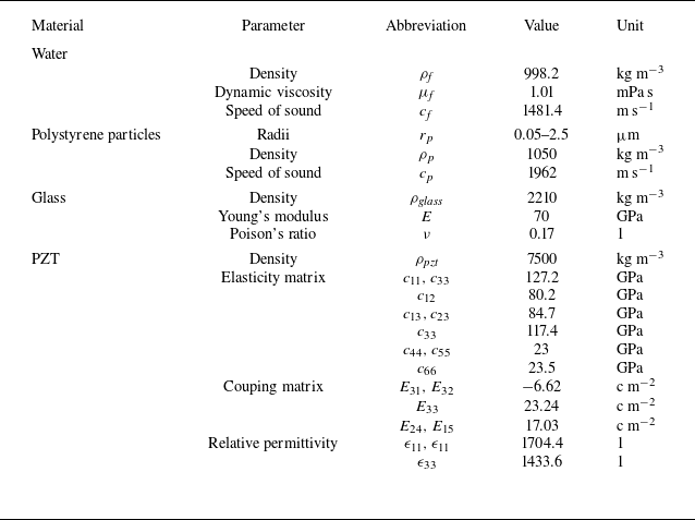
We conducted numerical simulations of acoustic streaming and acoustophoretic motion of polystyrene particles with particles driven by both the acoustic streaming-induced drag force (Stokes Reference Stokes1851) and the acoustic radiation force (Gor’kov Reference Gor’kov1962). See table 1 for particle and fluid properties, and refer to the appendix for the numerical set-up. The two-dimensional standing wave field in figure 1(d) can be established when two perpendicular walls (e.g. bottom and left walls) harmonically vibrate in phase at the same amplitude. The results presented subsequently are for a square channel with a side length of 1.6 mm, unless otherwise stated. Our simulations revealed that this mode allows for acoustophoretic tweezing of microparticles as small as 1.8
 $\mu$
m in diameter (i.e.
 $r_{p}^{\textit{min}}\approx 0.9$
 $\mu$
m). This is significantly smaller than the limit particle size found in a half-wavelength resonance (figure 1
a, b), where
 $r_{p}^{\textit{min}}\approx 2.1$
 $\mu$
m. Based on these insights, we will demonstrate how to modify the particular resonance (figure 1
d) in a square channel to bring it closer to the desired one for suppressing acoustic streaming and reducing the minimum particle size
 $r_{p}^{\textit{min}}$
. It is important to note that for each configuration, a series of simulations of acoustophoresis of particles (with continually decreasing sizes) were conducted to determine
 $r_{p}^{\textit{min}}$
. Here,
 $r_{p}^{\textit{min}}$
was defined as the smallest particle radius that results in trapping by acoustic radiation force, rather than being driven into the streaming streamlines.
Key properties of materials used in simulations.

2.2. Shaped channels for acoustic streaming suppression
One practical approach to achieve the desired resonance for suppressing acoustic streaming velocity may involve introducing circular walls into the flat fluid–solid interface (Yang et al. Reference Yang2025). In this study, we present numerical results from square channels with rounded corners to investigate the evolution of acoustic streaming patterns and magnitudes in channels with varying sizes of round corners and their effects on acoustophoretic motion of particles. As illustrated in figure 2(a), a square channel with a side length of
 $L=1.6$
mm and rounded corners of varying
 $R/L$
from 0.05 to 0.5 was considered. For each specific shape, the acoustic field, acoustic streaming and acoustophoretic motion of particles of different sizes were solved to assess its effectiveness in acoustic tweezing of microscopic particles.
Acoustic streaming suppression in square channels (of length
 $L$
) featuring rounded corners (of radius
 $R$
). (a) The model; (b) the evolution of the targeted acoustic resonance in channels with varying
 $R/L$
, where background colours represent normalised acoustic pressure magnitudes and acoustic pressure nodes are marked by green curves; (c) the variation of limiting velocities (
 $u_L$
) on the first-quadrant boundaries in channels with varying
 $R/L$
; (d) the minimum particle radius (
 $r_{p}^{\textit{min}}$
) that can be manipulated by the acoustic radiation force in channels with varying
 $R/L$
.

The evolution of the targeting acoustic resonance in rounded-square channels of varying
 $R/L$
is shown in figure 2(b). It can be seen that as
 $R/L$
increases from 0.05 to 0.5, the shape of pressure nodal lines gradually changes from a square to rounded squares, and eventually to a circle (specifically, the (0, 1) mode, where
 $m$
and
 $n$
in an (
 $m$
,
 $n$
) mode indicate the number of nodal diameters and circles, respectively). It is worth noting that several studies in the literature have examined outer acoustic streaming fields in cylindrical cavities, including axial modes (with
 $m=n=0$
) (Pavlic & Dual Reference Pavlic and Dual2021) and cross-sectional circumferential modes (with
 $m\ne 0$
,
 $n=0$
) (Lei et al. Reference Lei, Cheng and Li2020a
; Gerlt et al. Reference Gerlt, Paeckel, Pavlic, Rohner, Poulikakos and Dual2022). However, outer acoustic streaming in cross-sectional radial modes (with
 $m=0$
,
 $n\ne 0$
) remains unexplored.
Figure 2(b) shows that as
 $R/L$
increases, the parallelism between the pressure nodes and the boundaries is enhanced, which coincides with the case discussed earlier upon figure 1(c), indicating that a circular channel might be the ideal shape for acoustophoretic tweezing of nanoparticles. This conclusion is further supported by comparing the limiting velocities on the shaped boundaries. As plotted in figure 2(c), it is observed that at the same acoustic pressure amplitude, the limiting velocity in rounded-square channels of different
 $R/L$
generally decreases with the increase of
 $R$
, indicating that a lower acoustic streaming velocity (and therefore better capability in acoustophoretic tweezing of nanoparticles) is achieved in channels with higher roundness. This finding aligns well with the modelled particle acoustophoresis, where
 $r_{p}^{\textit{min}}$
falls with increasing
 $R/L$
(for
 $R\ne 0$
), as shown in figure 2(d). Modelling results also suggest that
 $r_{p}^{\textit{min}}$
starts to fall below 0.5
 $\unicode {x03BC}$
m in a rounded-square channel where
 $R/L\gt \sim 0.27$
.
As an example, the acoustofluidic fields and the acoustophoretic motions of particles of different sizes in a channel where
 $R/L=0.45$
were presented in figure 3. Detailed discriptions on the numerical implementation and mesh-convergency studies can be found in Appendix A.1. The outer acoustic streaming field exhibits a 16-vortex pattern, as shown in figure 3(b), which is similar to that in the square channel (where
 $R=0$
). As demonstrated in figure 3(d), with the decrease of the particle size, the rotational outer acoustic streaming imposes larger influences on the particle movements near the boundaries. Nevertheless, figure 3(d) demonstrates that in a channel with
 $R/L=0.45$
, polystyrene particles with radii of 150 nm and 100 nm in the whole cavity can be precisely patterned to the acoustic pressure nodes by the primary acoustic radiation forces, which are presented in figure 3(b). For particles with a radius of 50 nm, near-boundary particles exhibit vortical motions under the dominant effect of acoustic streaming and particles in the central region can also be driven into the streaming streamlines after being trapped towards the pressure nodes by the primary acoustic radiation forces.
Examples of acoustofluidic fields (normalised) and acoustophoretic patterning of polystyrene nanoparticles in a rounded-square channel where
 $R/L=0.45$
. Distributions for (a) acoustic pressure at resonant frequency
 $f = 1.0999$
MHz, (b) acoustic radiation force, (c) outer acoustic streaming and (d–f) acoustophoresis are presented. In panels (d–f), the background colours represent the normalised Gor’kov potential and the green lines illustrate the trajectories of particles (represented by white dots) with a radius of
 $r_{p}$
. Please see supplementary movies 1–3 available at https://doi.org/10.1017/jfm.2026.11207.

Figure 2(c) indicates that the overall strength of acoustic streaming decreases in channels with increasing roundness (
 $R/L$
), while the amplitude of acoustic pressure remains constant in channels of varying shapes. An extreme case was observed in a channel where
 $R/L=0.5$
(i.e. a circular channel), which results in zero limiting velocity and thus zero outer streaming velocity. Consequently, it, in theory, could enable acoustophoretic patterning of particles of any size by acoustic radiation forces. Next, we experimentally investigate the circumferential modes in a circular channel and their capability in acoustophoretic patterning of nanoparticles.
2.3. Experimental investigation of acoustophoretic tweezing of nanoparticles
The experiments were conducted in a glass capillary, which is a commonly used device for ultrasonic particle manipulations (Liu et al. Reference Liu, Lei, Cheng, Li, Ji, Huang and Guo2021). Figure 4 presents a schematic of the acoustofluidic tweezers system. A planar piezoelectric transducer (PZT, COSSON) was used to generate ultrasonic standing wave fields in the glass capillary with an inner diameter of 1.6 mm (Quartz, ZCQ). The glass capillary has a length of 50 mm and a square cross-section on the outside with a side length of 2.2 mm, which ensures a secure attachment of the glass and PZT. The PZT has dimensions of 10
 $\times$
5
 $\times$
1 mm (length
 $\times$
width
 $\times$
thickness), which was actuated by sinusoidal signals using a function generator (AFG1062, Tektronix), amplifed by a power amplifier (DPA2698, JUNTEK) and displayed on an oscilloscope (TBS1102B, Tektronix). The PZT had a fundamental thickness resonance frequency of 2 MHz, but it also showed good performance at frequencies around 3 MHz. The capillary was sealed at one end by a cover slip (thickness of 0.17 mm), which stops the flow and provides optical access. An isosceles right triangular prism (where a thin layer of aluminium was coated on the inclined surface) was placed next to the coverslip. This enables imaging of particle patterns on the cross-section of the channel using an upright microscope (XSP-63XDV, Shang Guang) with a magnification of 40
 $\times$
. A chip holder was designed to clamp different parts of the device. Fluorescent polystyrene particles (Yuan Biotech) were mixed with distilled water to create a uniform fluid–particle mixture. The particles used in this study had radii of 2500, 500, 250, 150, 100 and 50 nm. In experiments, particle solutions were injected into the channel from the open end of the capillary. Images of particle patterns were taken at a plane a few millimetres away from the cover slip to eliminate the side effects of boundary-driven acoustic streaming that could potentially be generated near it. Since the experimentally observed (0, 1) mode in such a system is usually distorted from the ideal one (Lei et al. Reference Lei, Cheng, Liu, Li and Guo2020c
), we will instead demonstrate nanoparticle patterning in a higher (0, 3) mode.
Schematic of the acoustic tweezers system for acoustofluidic manipulation of nanoparticles.

Part of the experimental results are summarised in figure 5(f), with the corresponding modelled results in the theoretical acoustic mode included for comparison. It was observed that at a frequency of 3.017 MHz, nanoparticles of various sizes were organised into three circles, as expected from numerical simulations shown in figure 5(e). To prevent the potential side effects of a ‘too high’ particle concentration on acoustic tweezers experiments (Hammarstrom, Laurell & Nilsson Reference Hammarstrom, Laurell and Nilsson2012), a low concentration of 0.05 mg ml−1 (0.005 %wt) for most particles was used. Similar results were obtained with 0.02 mg ml−1 and 0.01 mg ml−1 solutions (figure S1 in the supplementary material), demonstrating the method’s capability in acoustophoretic trapping of particles at low concentrations. As shown in figure S3, the inter-particle distances for the concentrations presented are generally much larger than five times the particle diameter, indicating that the inter-particle force is negligible when ultrasound is applied (Saeidi et al. Reference Saeidi, Saghafian, Haghjooy Javanmard, Hammarström and Wiklund2019). Theoretical calculations for the distance between dispersed particles in water solutions showed that the average particle distance in solutions with concentrations of 0.05 mg ml−1 and 0.5 mg ml−1 are approximately 44.48
 $r_{p}$
and 20.64
 $r_{p}$
, respectively. The progression of particle focusing from disorder to structured patterns at various time points can be found in figure S2. It is important to note that the speed at which particles are focused in the channel of such a system depends on the magnitudes of the acoustic radiation force. This force is closely tied to the device’s performance, which can vary significantly between devices with different configurations (including the type of PZT and its coupling with the capillary) and the actuating parameters, such as driving voltages and frequencies.
Experimental acoustic tweezing of nanoparticles via acoustic radiation forces, with comparison to the modelled acoustophoresis of nanoparticles in an ideal acoustic resonance. (a) Circular reduced-fluid model, where harmonic vibrations of one-quarter of the entire boundary were applied to simulate the acoustic fields. (b) Modelled acoustic pressure field for the ideal (0, 3) acoustic resonant mode at resonant frequency
 $f = 2.9984$
MHz. (c) Corresponding acoustic radiation force field, with the background colours representing the distribution of Gor’kov potential. (d) Acoustic streaming velocity (
 $\boldsymbol{{u_{2}}}$
) is zero everywhere. (e) Trajectories of nanoparticles of varying sizes, where the orange curves indicate zones of Gor’kov potential minima that are shown in panel (c). (f) Experimental acoustic tweezing of nanoparticles with different sizes (with a radius of
 $r_{p}$
) at a peak-to-peak voltage of 4 V. The particle solution was maintained at a low concentration of 0.05 mg ml−1, where the average particle distance is approximately 44.48
 $r_{p}$
, except for a concentration of 0.5 mg ml−1 (with an average particle distance of about 20.64
 $r_{p}$
) for the nanoparticles with
 $r_{p}=$
50 nm.

Figure 6(a) displays cross-sectional views of the patterns of particles at various depths of the channel. Consistent patterns were observed at different depths of the channel, indicating uniform particle rings along the channel. The cross-sectional views align well with measurements from side views of the channel, as shown in figure 6(b), where six lines of focused particles, two from each ring, are visible along the length, further supporting the presence of uniform particle rings along the channel.
Demonstrations of acoustic particle focusing along the length of the fluid channel. (a) Cross-sectional views of the focused particles with a radius of 500 nm at various depths of the channel, where
 $z$
represents the distance to the coverslip–water interface. (b) Side views of the focused particles in the channel at
 $y=0$
.

Particle image velocimetry (PIV) was used to analyse the motion of 5
 $\unicode {x03BC}$
m particles, as shown in figure 7(a). Based on the PIV results, calculations regarding the acoustic radiation force were conducted. Following Stokes’ drag, it was established that a velocity of 0.25 mm s−1 for 5
 $\unicode {x03BC}$
m polystyrene particles yielded an acoustic radiation force of approximately 12 pN. Both the PIV experiments and the modelling (figure 7
b) demonstrate that the acoustic radiation force is highest within the inner circle and decreases towards the channel boundaries. However, minor distinctions were observed in the acoustophoretic tweezing of nanoparticles of varying sizes. In some instances, the nanoparticles did not conform to perfect circular patterns. This deviation could be attributed to several factors. First, the interaction of different layers within this specific acoustofluidic device configuration, especially with a square outer cross-section of the capillary, might impact the circularity of the acoustic pressure nodes. Second, the pattern could have been distorted by nearby modes with similar resonant frequencies or by the non-axisymmetric mounting of the PZT. Third, the channel’s cross-section may deviate from a perfect circle due to manufacturing imprecisions. Fourth, the experimental resonant frequencies may not have been precisely captured due to slight discrepancy between the experimental and modelled frequencies, as well as potential fluctuations in resonant frequencies when the channel is filled with solutions containing particles of differing sizes. Fifth, the decrease in particle radius leads to a rapid reduction in both the particle volume and acoustic radiation force, making it more difficult to achieve clear imaging for smaller particles due to the aforementioned uncertainties. Despite these uncertainties, the experimental results, in conjuction with the modelling, sufficiently demonstrated the acoustic tweezing of nanoparticles at sub- or low-MHz frequencies. The experiments relied on the mechanism that boundary-driven acoustic streaming is highly suppressed (or fully suppressed for the idealised acoustic resonances) in the fluid cavity. This reduction in acoustic streaming-induced drag force on suspended particles allowed for reliable positioning at the pressure nodes by the acoustic radiation force.
(a) PIV result for the measured particle motion in the (0, 3) mode. (b) The modelled acoustic radiation force field, where the green circles represent the acoustic pressure nodes. The exemplified arrow represents a velocity of 0.5 mm s−1.

With fully suppressed boundary-driven acoustic streaming, the acoustic radiation forces should be capable of tweezing particles of any size, as presented in figure 5(c–e). However, as discussed earlier, complete suppression of acoustic streaming relies on perfect parallelism between the pressure nodes and the boundaries. Any distortion of the acoustic pressure nodes or non-parallelism may result in non-zero acoustic streaming velocity, potentially increasing the lower limit of particle trapping size
 $r_{p}^{\textit{min}}$
. To confirm this, we conducted a closer examination of the near-boundary trapping (i.e. the outermost ring) of 1
 $\unicode {x03BC}$
m particles and observed the presence of acoustic streaming vortices in distorted regions (please refer to the PIV results in figure S4). These vortices can trap particles at specific positions near their centre, while in regions with parallel pressure nodes to the boundary, particles exhibited ring-trapping similar to the central ones.
Although theoretically, for the (0,
 $n$
) modes, the pressure nodal lines are circles that are strictly parallel to the circular boundaries (as shown in figure 5
b), the experimentally observed pressure nodes are distorted from circles (see the particle patterning presented in figure 5
f). The residual acoustic streaming caused by the distortion of pressure nodes may increase the minimum particle radius,
 $r_{p}^{\textit{min}}$
, that can be manipulated by the acoustic radiation forces in the experiments. Here, the acoustophoretic tweezing of nanoparticles with sizes as small as 100 nm was demonstrated. Based on the above-mentioned analyses, one would expect that an (
 $m$
,
 $n$
) mode with non-zero
 $m$
and
 $n$
can also suppress acoustic streaming to some extent when compared with the (
 $m$
, 0) mode. The (
 $m$
, 0) mode is typically only able to trap microscale particles (Goddard & Kaduchak Reference Goddard and Kaduchak2005; Kalb et al. Reference Kalb, Olson, Sosik, Woods and Graves2018; Gerlt et al. Reference Gerlt, Paeckel, Pavlic, Rohner, Poulikakos and Dual2022; Lei et al. Reference Lei, Cheng and Li2020a
; Lei et al. Reference Lei, Cheng, Li and Guo2020b
). Results of control experiments for 5
 $\unicode {x03BC}$
m and 1
 $\unicode {x03BC}$
m particles in a (3, 0) mode can be found in figure S5.
2.4. Full-device modelling
Despite the good agreements between the experimental measurements of nanoparticle focusing and numerical modelling of acoustophoresis in the idealised acoustic resonance with reduced-fluid models, we present here a full-device model incorporating both the PZT and the glass capillary, as shown in figure 8(a), to further investigate how the glass outer square shape affects the performance of nanoparticle focusing in such an experimental device. Details of numerical implementations of the full-device model can be found in Appendix A.2.
Full-device modelling of acoustofluidic fields and acoustophoresis in the fluid channel of the experimental device. (a) Two-dimensional model, which represents a cross-section of the capillary-PZT device. (b) Modelled acoustic pressure field (
 $|p_1|$
, Pa) at resonant freqeuncy
 $f = 2.9979$
MHz. (c) Corresponding acoustic radiation force field, with the background colours representing the distribution of Gor’kov potential (J). (d) Modelled acoustic streaming field (
 $\boldsymbol{{u_{2}}}$
, m s−1). (e) Modelled acoustophoresis of polystyrene nanoparticles of various sizes with radii (
 $r_{p}$
) ranging from 50 to 500 nm, where the orange curves indicate zones of Gor’kov potential minima that are shown in panel (c).

The modelled acoustic pressure, acoustic radiation force, outer acoustic streaming and acoustophoresis of nanoparticles of various sizes at the resonance frequency 2.9979 MHz are presented in figure 8(b–e). Figure 8(b) shows that the outer square cross-section influences the acoustic resonant mode by distorting the perfectly ring-shaped acoustic resonance, particularly on the outermost ring. This distortion causes a misalignment between the outermost ring and the water–glass boundary, leading to a disturbance (i.e. non-zero streaming, figure 8 d) in nanoparticle focusing, especially for those on the outermost ring.
The modelled particle tracing for polystyrene nanoparticles of varying sizes was in quantitative agreement with our experimental measurements presented in figure 5(f). First, for
 $r_{p}=$
500 nm particles, stable trapping and no vortical motion are observed on all three rings. Second, for
 $r_{p}=$
250 nm particles, stable trapping is observed on the two inner rings while vortical motion is observed on the outermost ring, inducing stable trapping in positions near the Gor’kov potential minima. Third, for
 $r_{p}=$
150 nm particles, stable trapping is observed on the two inner rings, while vortical motion is observed on the outermost ring, inducing partial trapping in positions near the centre of several streaming vortices. Fourth, for
 $r_{p}=$
100 nm particles, stable trapping is observed on the two inner rings, but no trapping on the outermost ring. Fifth, for
 $r_{p}=$
50 nm particles, stable trapping is observed on the inner ring, but no trapping on the outermost ring, and the boundary streaming has some influence on the particle trapping on the middle ring. These results suggest that the experimental device could be further optimised to achieve faster and better focusing of nanoparticles, particularly for particles that are 100 nm and smaller. Nonetheless, both experiments and numerical simulations have demonstrated the mechanism we proposed, showing that the critical particle size in a fluid channel can be significantly reduced by aligning the acoustic pressure nodes with the fluid–solid boundaries. Any misalignment between them would induce residual streaming, leading to an increase in the critical particle size.
3. Conclusion and outlook
We have proposed a new mechanism for the suppression of acoustic streaming in wavelength-scale resonant acoustofluidic devices operating at sub- or low-MHz frequencies. With suppressed acoustic streaming, we have successfully demonstrated acoustophoretic tweezing of nanoparticles using acoustic radiation forces both numerically and experimentally. We introduced a generalised square fluid model (with a side length of
 $L$
) featuring rounded corners (of radius
 $R$
) and assessed the efficiency of channels with various configurations in acoustic patterning of micro- and nanoparticles by determining the minimum particle size (
 $r_{p}^{\textit{min}}$
) that can be trapped by the acoustic radiation force. Our findings revealed that increasing
 $R/L$
enhances the parallelism between the pressure nodes and the boundaries, resulting in a lower
 $r_{p}^{\textit{min}}$
in channels with higher roundness. Therefore, to achieve acoustophoretic patterning of nanoparticles of the smallest possible size (
 $r_{p}^{\textit{min}}$
), it is recommended to use a channel with the highest roundness (
 $R/L$
), ideally a circular channel, where the effects of boundary-driven acoustic streaming on particle motion are completely eliminated throughout the fluid, enabling the theoretical tweezing of particles of any size through acoustic radiation forces. This research not only sheds light on the control of boundary-driven acoustic streaming, but also paves the way for more effective acoustic tweezing of biological nanoparticles, such as bacteria, viruses and exosomes. In terms of nanoparticle manipulation, this study not only presents a novel method for arranging and enriching nanoscale particles, but also offers theoretical guidance for single nanoparticle manipulation and analysis. Future work will focus on broadening this research to include three-dimensional (3-D) acoustophoretic manipulation of nanoparticles. While creating a 3-D microchannel to generate ideal acoustic resonances may be challenging with conventional microfabrication techniques, 3-D printing (Bauer, Crook & Baldacchini Reference Bauer, Crook and Baldacchini2023; Xin et al. Reference Xin, Li, Hao and Li2023; Li et al. Reference Li, Jia, Duan, Xiao, Qiao, Liang, Wang, Chen, Wu and Lu2024) emerges as a promising solution.
Supplementary material and movies
Supplementary material and movies are available at https://doi.org/10.1017/jfm.2026.11207.
Funding
This work was supported by the Natural Science Foundation of Guangdong Province (2024A1515030112, 2025A1515011673, 2021A1515010244 and 2023A0505050135) and the National Natural Science Foundation of China (11804060).
Declaration of interests
The authors report no conflict of interest.
Data availability statement
Data available on request from the authors.
Appendix A. Numerical implementations
In this study, two types of numerical models were used: reduced-fluid models and full-device models. These models are commonly found in the literature for modelling acoustofluidic fields and acoustophoresis of particles in fluid channels of acoustofluidic devices. A reduced-fluid model focused solely on the fluid domain, making it simpler and more computationally efficient compared with a full-device model, which considers the coupling of different layers of an acoustofluidic device. All numerical simulations were conducted using COMSOL 6.0. Please refer to table 1 for all material parameters.
A.1. Reduced-fluid models
For each configuration of reduced-fluid models, three COMSOL interfaces were implemented to model the acoustic fields, acoustic streaming fields and particle trajectories, and three studies were carried out. Here, we present the numerical details for two specific models: a nearly circular model with
 $R/L=0.45$
(please refer to figure 3 for additional results) and a circular model with
 $R/L=0.5$
(please refer to figure 5 for additional results). First, we used the ‘pressure acoustics, frequency domain’ interface to model the acoustic fields, including acoustic pressure (
 $p_1$
) and velocity (
 $\boldsymbol{u_1}$
), through a ‘frequency domain’ study. In particular, we solved the Helmholtz equation,
 \begin{equation} \bigtriangledown ^2p_1+p_1\omega ^2/c_f^2=0. \end{equation}
In the nearly circular model (with
 $R/L=0.45$
), acoustic fields in the cavity were generated by harmonic vibrations (with normal velocity
 $v_n$
) of two straight walls, with the remaining boundaries set as sound hard conditions, as depicted in figure 9(a). Resonant frequencies in different configurations were determined using a frequency sweeping method to identify the frequency that produces the maximum average acoustic energy density (
 $\langle E_{\textit{tot}}\rangle$
) in the cavity, as shown in figure 10(c). Mesh convergence studies were conducted to determine the mesh elements required for accurate results. Based on the mesh convergence study, we chose triangular mesh elements with a maximum size of
 $10\,\mu \textrm {m}$
for simulations, leading to an error below 1 % (see figure 10
b). This mesh size results in 65 940 mesh elements and 721 731 degrees of freedom.
Boundary conditions for numerical simulations of (a) acoustic fields and (b) acoustic streaming fields. The acoustic pressure (
 $p_1$
) was modelled by harmonic vibrations of two straight walls (highlighted) with normal velocity
 $v_n$
. The outer acoustic streaming field (
 $\boldsymbol{{u_{2}}}$
) was driven by limiting velocities (
 $u_L$
) in the tangential direction (
 $\boldsymbol{\tau }$
) of all boundaries. As shown in panel (c), a dense array of nanoparticles was released into the cavity at
 $t=0$
for each configuration.

Numerical simulations in the nearly circular model (with
 $R/L=0.45$
). (a) Triangular mesh elements with a maximum size of
 $a$
were used in the simulations. (b) Mesh-convergence studies were conducted, with
 $\langle E_{\textit{tot}}\rangle$
and
 $\langle {u_{2}}\rangle$
representing the average acoustic energy density and acoustic streaming magnitude in the fluid domain, respectively. (c) A frequency-sweeping study was employed to determine the resonance frequency. Here,
 $a$
and
 $f$
represent the maximum triangular mesh size and the actuating frequency, respectively.

Subsequently, the acoustic streaming fields (
 $\boldsymbol{u_2}$
) were modelled using a ‘creeping flow’ interface in a ‘stationary’ study. We solved the acoustic streaming using the limiting velocity method, which models the outer acoustic streaming by implementing limiting velocities (
 $u_L$
) on all walls, as depicted in figure 9(b). Outside the boundary layer, the following equations were solved:
 \begin{align}{\bigtriangledown} \boldsymbol{\cdot }\boldsymbol{u_2}&=0;\end{align}
 \begin{align}-\bigtriangledown p_2+\bigtriangledown ^2\boldsymbol{u_2}&=0.\end{align}
Finally, a ‘particle tracing for fluid flow’ interface was used, together with a ‘time-dependent’ study, to model the particle trajectories. The acoustophoretic motions of nanoparticles of various sizes (initially dense enough to cover the entire area, as shown in figure 9 c) were solved using Newton’s second law,
 \begin{equation} \sum \boldsymbol{F}=\boldsymbol{F_{\textit{rad}}}+\boldsymbol{F_d}=m_{p}\,{\mathrm{d}\boldsymbol{u_p}/{\mathrm{d} t}}, \end{equation}
where
 $m_p$
is the particle mass,
 $\boldsymbol{u_p}$
is the particle velocity, and
 $\boldsymbol{F_{\textit{rad}}}$
and
 $\boldsymbol{F_{d}}$
represent the acoustic radiation force and the drag force induced by acoustic streaming, respectively. The two forces on nanoparticles were calculated using Gor’kov potential (Gor’kov Reference Gor’kov1962) and Stokes law (Stokes Reference Stokes1851), based on the acoustic and streaming fields modelled in the previous steps, following
 \begin{align} \boldsymbol{F_{\textit{rad}}}&=-\bigtriangledown {U}, \end{align}
 \begin{align} \boldsymbol{F_d}&=6\pi \mu _{\!f} r_{p}\boldsymbol{u_2}, \end{align}
with
 $U$
,
 $\mu _{\!f}$
,
 $r_{p}$
representing the Gor’kov potential, fluid dynamic viscosity and particle radius, respectively.
The numerical simulation of acoustic fields in the circular model is similar to the process previously described. The only difference lies in the fact that the acoustic resonances in the cavity were generated by harmonic vibrations of one-quarter of the entire boundary, as indicated in figure 5(a). Figure 11 shows the results for the mesh-convergence study and frequency-sweeping in the circular model.
Numerical simulations in the circular model (with
 $R/L=0.5$
). (a) Mesh-convergence studies were conducted, with
 $\langle E_{\textit{tot}}\rangle$
representing the average acoustic energy density in the fluid domain. (b) A frequency-sweeping study was conducted to identify the resonance frequency. Here,
 $a$
and
 $f$
represent the maximum triangular mesh size and the actuating frequency, respectively.

A.2. Full-device models
As shown in figure 12(a), a two-dimensional full-device model was used to simulate the acoustofluidics and acoustophoresis of nanoparticles with varying sizes in the fluid channel cross-section. Five COMSOL interfaces were employed in the simulations. Similar to the reduced-fluid models mentioned earlier, interfaces such as ‘pressure acoustics, frequency domain’, ‘creeping flow’ and ‘particle tracing for fluid flow’ were used to model the acoustic fields, acoustic streaming fields and particle trajectories in the fluid domain, respectively. Furthermore, the ‘electrostatics’ and ‘solid mechanics’ interfaces were used to model the solid domains, including glass and PZT, in the full-device model. Specifically, the ‘electrostatics’ interface was applied to the PZT and coupled to the ‘solid mechanics’ interface through the ‘piezoelectricity multiphysics’ interface, both modelled with a ‘frequency domain’ study. Charge conservation with a peak-to-peak electric potential amplitude of 4 V was imposed on the entire PZT. In the ‘solid mechanics’ interface, the glass layer and PZT layer were represented as linear elastic material and piezoelectric material, respectively. Rayleigh damping was considered to address the damping of solid materials. The coupling of solid mechanics to the fluid layer was achieved through an ‘acoustic-structure boundary multiphysics’ interface, eliminating the need to specify additional boundary vibrations on the water–glass interface in the ‘pressure acoustics, frequency domain’ interface.
Numerical simulations in the full-device model. (a) Model size and mesh consititution. (b) A frequency-sweeping study was conducted to identify the resonance frequency. (c) Modelled distribution of acoustic pressure in the fluid at the resonant frequency of 2.9979 MHz. (d) Mesh-convergence studies were conducted, with
 $a_{w\textit{ater}}$
,
 $a_{\textit{pzt}}$
and
 $a_{\textit{glass}}$
representing the maximum size of triangular mesh elements in the water, PZT and glass domains, respectively.
 $\langle E_{\textit{tot}}\rangle$
and
 $\langle {u_{2}}\rangle$
represent the average acoustic energy density and acoustic streaming magnitude in the fluid domain, respectively.

Results for mesh-convergence studies and frequency-sweeping are presented in figure 12. In this full-device model, we introduced three mesh parameters,
 $a_{w\textit{ater}}$
,
 $a_{\textit{pzt}}$
and
 $a_{\textit{glass}}$
, representing the maximum size of triangular mesh elements in the water, PZT and glass domains, respectively. Based on the mesh-convergence studies, we chose the following mesh parameters for the simulations, leading to mesh-induced errors below 1
 $\%$
:
 $a_{w\textit{ater}}=50$
 $\unicode {x03BC}$
m,
 $a_{\textit{pzt}}=60$
 $\unicode {x03BC}$
m and
 $a_{\textit{glass}}=40$
 $\unicode {x03BC}$
m. These mesh sizes result in 65 940 mesh elements and 721 731 degrees of freedom.