Introduction
Electromagnetic (EM) absorbers play an important role in the absorption of incident EM energy by minimizing reflection and transmission. They have potential in several applications such as radar cross section (RCS) reduction in stealth technology, radio-frequency (RF) energy harvesting, mutual coupling reduction between antennas, electromagnetic interference (EMI) suppression, and electromagnetic compatibility [Reference Yu, Besteiro, Huang, Wu, Fu, Tan, Jagadish, Wiederrecht, Govorov and Wang1]. Conventional absorbers such as Salisbury screens were designed for microwave absorption at a single frequency. A uniform-resistive sheet of free-space impedance is coated on a λg/4 dielectric substrate terminated with the ground [Reference Fante and Mccormack2]. Since the thickness of a conventional absorber is frequency-dependent, it exhibits narrow band absorption. The Jaumann screen overcomes this limitation by placing more than one dielectric spacer at the cost of increasing the overall effective thickness. Hence, these absorber kinds are not recommended in real-time applications [Reference Ke, Xin, Xinyu and Peng3].
Two-dimensional frequency selective surfaces (FSSs) advancement makes microwave absorption possible at the compact scale [Reference Rhee, Yoo, Kim, Kim and Lee4]. First, an I-shaped electric field-driven LC resonator backed with a simple transmission line is proposed for the near-unity perfect EM-wave absorption at the X-band [Reference Landy, Sajuyigbe, Mock, Smith and Padilla5]. The high Q-factor of the plasmonic resonances involved in these structures limits the absorption bandwidth. Dual [Reference Liu, Lan, Li, Zhao and Zhou6], triple [Reference Shukoor, Kumar and Dey7], quad [Reference Chaurasiya, Ghosh, Bhattacharyya and Srivastava8] to undeca-band [Reference Shukoor, Dey and Koul9] absorbers are demonstrated in the literature. But, in real-time needs, broadband absorption is preferable to multiband due to reasons such as fabrication tolerances and its utilization in more than one application.
On the contrary, circuit analog absorbers (CAAs) and capacitive circuit absorbers (CCAs) are effective techniques for designing broadband absorbers. CAAs are a promising solution because of their non-zero reactive impedance that enables frequency tuning for broader bandwidth. The real part helps in matching input impedance to free-space impedance (Z 0 = 377 Ω) [Reference Shukoor and Dey10]. Mohammad et al. proposed a broadband polarization-insensitive CAA that shows a minimum 95% absorption bandwidth from 2.26 to 5.76 GHz (sub-6 GHz range) for RCS applications [Reference Shukoor and Dey11]. A dual-layered substrate triple square-loop absorber loaded with 12 lumped resistors is demonstrated [Reference Ghosh, Bhattacharyya and Srivastava12], which results in fractional bandwidth (FBW) of 114% for C, X, and Ku-band applications. A novel compact broadband absorber for X- to Ka-band applications is proposed, where two circular rings loaded with four lumped resistors each on both sides of the substrate are used for design compactness [Reference Shukoor and Dey13]. A dual octagonal single-layer CAA loaded with eight lumped resistors exhibits 73.68% FBW, and 20° angular stability is presented in [Reference Li, Gao, Cao, Li, Zhang and Zhang14]. In certain configurations of absorbers, broad angular stability under transverse magnetic (TM) oblique incidence and wider bandwidth lumped resistors and vias were also used [Reference Chen, Luo, Ding, Zhao, Feng and Jiang15].
Generally, microwave absorbers require broader bandwidth with extensive adaptability, compact profile, and improved angular stability for practical applications. Grating lobes are also modifiable in the absorption range when the incidence angle goes further than normal incidence. However, it would decrease the influence of grating lobes if the unit cell periodicity is optimized appropriately. By keeping all these in mind, an FSS-based CAA is proposed where the novelty of the design lies in the placing of design on the top of an air-spacer with the dielectric substrate for the broader bandwidth, better angular stability, and a minimum number of lumped resistors (a total of four per cell) were used.
In this paper, a broadband absorber is proposed, consisting of a modified circular ring with four circular patch FSSs loaded with four chip resistors on each unit cell. The FSS is loaded on the bottom side of the substrate. The idea behind the design of this absorber is greater bandwidth (use a low permittivity substrate such as an air-spacer) and wide angular stability (increase the permittivity loaded with the FR-4 substrate), in which the novelty of the design lies. The proposed design is later investigated for the oblique incidences, and up to 45° stability in the response is observed for both Transverse Electric (TE) and Transverse Magnetic (TM) incidences. RCS analysis of the design is verified by stacking with a 28 GHz microstrip patch antenna (MSA) on the top of it.
The paper is organized as follows. In Section “Unit cell design and the simulation results,” the design of unit cell, simulation results, and equivalent circuit model of the proposed absorber are presented. The surface current distribution is also discussed in Section “Investigation of the physical reason behind broadband absorption,” and the reason behind the broadband absorption phenomena is detailed. The proposed sample is fabricated, and the measured results are compared with the simulation result in Section “Fabrication and measurement.” The RCS analysis of the proposed absorber is investigated by stacking a 28 GHz MSA prototype, and the results are discussed in Section “RCS reduction analysis of the proposed absorber.” Finally, the conclusion of this study has drawn in Section “Conclusion.”
Unit cell design and the simulation results
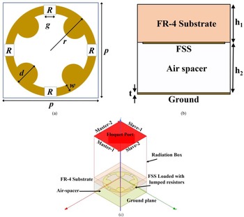
The proposed absorber unit cell consists of lumped resistor-loaded FSS underneath a thin dielectric substrate, which is mounted on the perfect ground with the help of an air-spacer, as shown in Fig. 1. A 0.8 mm thin FR-4 substrate (relative permittivity ɛr = 4.4, and loss-tangent tan δ = 0.02) is used as a dielectric spacer for this design. A 0.035 mm thin copper film (with conductivity σ = 5.8 × 10⁷) is chosen as the metallic layer to serve the purpose. The performance of the unit cell is optimized in a finite-element method-based EM solver ANSYS HFSS. Here, master–slave periodic boundary conditions (PBCs) were applied along the x–y plane to mimic the infinite metasurface, and floquet port is used for the excitation along the z-direction (see Fig. 1(c)). The frequency sweep has been maintained from 5 to 40 GHz such that the desired broadband performance falls under that range, and the adaptive meshing technique is implemented in the EM solver for simulation purposes.
Schematic view of the proposed unit cell: (a) FSS and (b) side view, (c) simulation setup of the proposed absorber in EM solver along with PBCs and floquet port excitation.

The final dimensions of the unit cell obtained are: p = 5.5 mm, r = 2.6 mm, g = 0.5 mm, w = 0.4 mm, d = 1.264 mm, and R = 200 Ω. Here, p is the largest dimension of the unit cell, r is the radius of the modified circular ring, g is the gap for the housing of chip resistors, w is the width, d is the diameter of the circular patch, and R is the value of the lumped resistors used for this design, as shown in Fig. 1.
When an EM wave strikes the absorbing surface, the equation of the absorptivity A(ω) can be obtained from the law of energy conservation as below (since the scattering and diffraction would be taken care of in the optimization of the unit cell periodicity):

where $R( \omega ) = S_{11}^2 ( \omega )$ is the reflectance from the absorber surface, $T( \omega ) = S_{21}^2 ( \omega )$
 is the transmittance through the absorber. Since the other end of the absorber is perfect ground, T(ω) will be zero. The near-unity absorption would be achieved if the reflectance is minimum, and this is possible if the complex input impedance (Zin) at the surface exactly matches with free-space impedance Z 0 (=377 Ω).
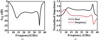
A CAA effectively designs absorption media over a broad range. The narrow bandwidth problem can be overcome by selecting an appropriate resistor equivalent that converts the metallic layer into a high-impedance surface (HIS) over the wide range. The non-zero reactive component of the impedance in CAAs serves to modify resonant frequencies for even absorption. The simulated reflection coefficient of the proposed absorber is shown in Fig. 2(a). It seems clear that the reflectance is <−10 dB over the frequency range from 10.55 to 36.03 GHz (over 25.48 GHz bandwidth and 109.4% FBW) with two reflection dips at 13.5 and 35.23 GHz having reflectances −17.18 and −24.9 dB, respectively. The reason for the reflectance over the broadband can be cleared from the real and imaginary parts of input impedance, in which the real part is nearly 230 Ω, and the imaginary part is close to zero over the broad range. The normalized real and imaginary parts of the input impedance with reference to a free-space impedance Z 0 (=377 Ω) are shown in Fig. 2(b).
Simulated (a) reflectance, S 11 (dB) and (b) real and imaginary parts of the normalized input impedance.

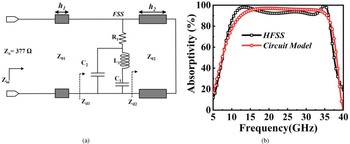
In this section, the transmission-line equivalent circuit model of the proposed absorber is shown in Fig. 3(a). Here, the FSS is modeled as a combination of a series RLC circuit and shunt capacitance (C 2) across the LC circuit. The reason for incorporating the C 2 capacitance in the equivalent circuit is to model the capacitance offered by the semi-circular patches of the FSS with reference to the ground. This C 2 loading in shunt will increase the overall capacitance, and the Q-factor ($Q = ( 1/2\pi ) \sqrt {L/C}$ ) reduces. The role of C 2 in achieving broad bandwidth is observed for the proposed design, and it is demonstrated with the simulation results of the EM solver in the next sections. The dielectric substrate and the air-spacer is modeled as transmission lines of lengths (h 1) and (h 2) with the corresponding characteristic impedances Z 01 (=Z 0/$\sqrt {\varepsilon _{r1}}$
 ) and Z 02 (=Zo), respectively. Here, the Keysight Advanced Design System (ADS) equivalent circuit model is used for extracting the lumped RLC values of the FSS. The extracted values are: R 1 = 203.5 Ω, L 1 = 0.461 nH, C 1 = 0.079 pF, and C 2 = 0.059 pF. In order to obtain the minimum reflection over the broadband, it is necessary to match input impedance (Zin) to free-space impedance with zero-imaginary part. The value of Zin is derived from the basic transmission-line theory as in [Reference Ghosh, Bhattacharyya and Srivastava12]:


(a) Equivalent circuit model of the proposed absorber. (b) Comparison of the absorptivity response of HFSS and circuit model.

The absorptivity obtained from the circuit model is compared with the response of the EM simulator, as shown in Fig. 3(b). A good matching is noted between the two responses with a slight deviation. The proposed absorber shows >90% absorptivity over X, Ku-, and Ka-bands with near-unity absorption at two frequencies at 13.5 GHz (with 98.08% absorptivity) and 35.23 GHz (with 99.7% absorptivity).
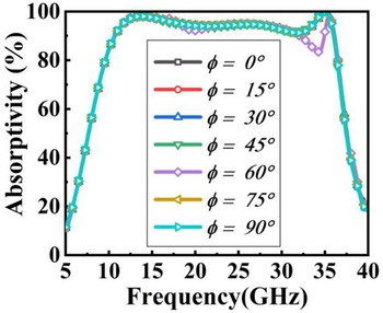
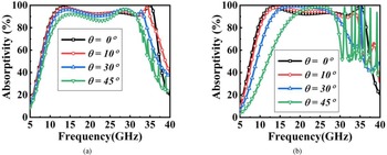
Later, the performance of the proposed design is investigated for different polarization angles under normal incidence in the azimuthal plane. The polarization angle (ϕ) is varied from 0 to 90° in steps of 15°, and the simulated response is depicted in Fig. 4. Due to the four-fold circular symmetry of the proposed architecture, the design shows polarization insensitiveness for different ϕ in the azimuthal plane. Along with that, the absorptivity response is studied for different oblique incidences under TE and TM modes. The electric field vector is always tangential to the metasurface for the TE case. The magnetic field and wavevector vary accordingly with oblique angles from 0 to 45° in steps of 15°. The absorptivity variation for different angles under the TE case is given in Fig. 5(a). It seems clear that the proposed design is stable up to 45° with 90% absorptivity. Under the TM mode, the magnetic field vector is always tangential to metasurface, electric field, and wave vector direction varies with incident angle. The absorptivity variation from 0 to 45° under TM incidence is shown in Fig. 5(b). It shows 90% absorptivity up to 45°, and a slight disturbance is observed at 45° due to grating lobes, as demonstrated in [Reference Abdul Shukoor and Dey16].
Simulated absorptivity variation for different polarization angles (ϕ) under normal incidence.

Variation of absorptivity for different polarization angles under (a) TE and (b) TM modes of oblique incidences.

On the contrary, for TE and TM, up to 45°, the grating lobes are beyond 32 GHz, which lies inside the operating band since the design operates from 10 to 35 GHz. Here, the authors have compromised the design due to the fabrication tolerance. If the unit cell periodicity is reduced by 1 mm (which means 4.5 mm), the grating lobes for the presented response (10–35 GHz) won't be disturbed. Still, it is also impossible to place all four chip resistors in a small area in practice. The grating lobe dependence on the incident angle and the cell periodicity is cleared from the expression given below:

where c is the velocity of light in vacuum, p is the periodicity of the unit cell, θ i is the angle of incidence, m is the order of the grating lobe, and f corresponds to the frequency at which the grating lobe begins to appear. At an incident angle >60°, the grating lobes are in the operating frequency range, and absorptivity reduction will increase.
Investigation of the physical reason behind broadband absorption
Surface current distribution analysis
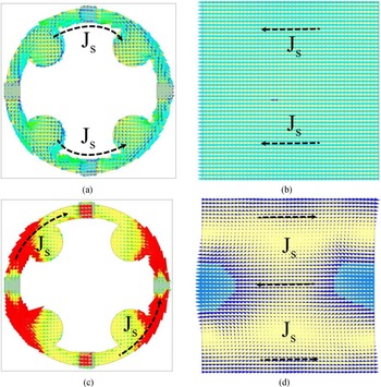
The surface current distributions of the FSS and bottom ground are investigated at two resonant frequencies, 13.5 and 35.23 GHz, to find the physical phenomena behind the near-unity absorption. When the electrical field excites the metallic surfaces of the absorber, the surface currents are induced in the metallic portion of the FSS and ground due to the excitation of tangential electric field components, which are in anti-parallel directions at 13.5 GHz, as shown in Figs 6(a) and 6(b). It seems clear that most of the currents are concentrated at the inside circular patches. These anti-parallel currents result in electric-dipole resonance (since the reflection phase is close to 180°, see Fig. 7), which constitutes the dielectric losses. These are solely responsible for the near-unity absorption at the resonant frequency. At 35.23 GHz, the same sort of anti-parallel surface current distributions is observed, with other surface current profiles (see Figs 6(c) and 6(d)). Here, the reflection phase has smooth zero-crossing (from Fig. 7), and this frequency corresponds to the magnetic dipole resonance. It is also worth investigating the impact of lumped resistors and semi-circular patches on the broadband absorption phenomena, and it is detailed in the next sections.
Surface current distribution of (a) FSS, (b) ground at 13.5 GHz, (c) FSS, and (d) ground at 35.23 GHz.

Simulated phase profile of the reflection coefficient (S 11) with frequency.

Study of the reflection phase for understanding the Fabry–Perot modes between the top FSS and ground
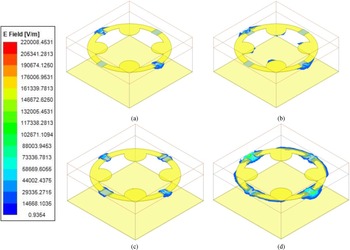
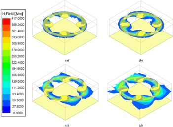
Different resonances are responsible for broadband absorption. Multiple reflections between the top FSS and ground result in the Fabry–Perot modes in the higher frequency regions, which can be cleared by visualizing the electric and magnetic field distributions. The simulated reflection coefficient phase is investigated, as depicted in Fig. 7. In general, in the phase profile of CAAs, the middle resonance is generated due to the effective height of top FSS with reference to ground (results in the Fabry–Perot mode in this design), and the phase profile is purely inductive before the resonance and purely capacitive after the resonance. From Fig. 7, at three frequencies S 11 phase is becoming zero. The magnitudes of electric and magnetic fields at different frequencies 13.5, 23.75, 32.25, and 35.23 GHz are depicted in Figs 8 and 9, respectively. At 35.23 GHz, the phase of S 11 moves inductive to capacitive resembles parallel resonance of the tank circuit. This dominance can be noted from magnitudes of the strong field stored in the air-spacer between the top FSS and ground (see Figs 8(d) and 9(d)) in comparison with other frequencies. The centered circular patches are responsible for the resonance at 35.23 GHz, and the outermost circular patches loaded with lumped resistors result in the lowest frequency at 13.5 GHz, and this would be the reason for the high Q-factor dip in the magnitude of S 11 at 35.23 GHz (see Fig. 2(a)) compared to 13.5 GHz.
Magnitude of the electric field distributions at (a) 13.5 GHz, (b) 23.75 GHz, (c) 32.75 GHz, and (d) 35.23 GHz.

Magnitude of the magnetic field distributions at (a) 13.5 GHz, (b) 23.75 GHz, (c) 32.75 GHz, and (d) 35.23 GHz.

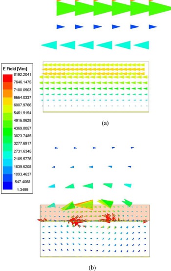
The dielectric substrate and air-spacer's vector E-field demonstrate the Fabry–Perot mode at 23.75 GHz. The standing wave pattern of E-field is observed in the substrate and air-spacer medium collectively, as detailed in Fig. 10. A quarter wave E- field pattern is observed with minimal tangential E-field near the ground and the maxima at the air–dielectric interface where the incident wave hits the design. The pattern is very clear in the case without FSS, and a slight disturbance is observed due to scattered fields in the presence of FSS.
Vector E-field distribution of the design (a) without FSS and (b) with FSS at 23.75 GHz.

The effect of lumped resistance in the broadband absorption
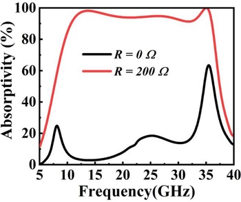
On the contrary, a CAA is a very successful method for broadband absorption. The problem of a limited range of bandwidth may overcome by using a lumped resistor equivalent that converts the metallic layer into an HIS. An impedance with a non-zero reactive component helps in tuning the resonant frequencies for uniform absorption when using CAAs. The reason behind the broadband absorption mechanism can be investigated by observing the variation of absorptivity by replacing resistance R with different values. The absorptivity variation is studied without losing the generality for R = 0 Ω and R = 200 Ω, as shown in Fig. 11. From the figure, it is clear that if R = 0 Ω, it means the impact of the lumped resistor is almost negligible, and the proposed design resembles the metallic FSS with negligible ohmic losses. Three resonances decide the extent of the broadband. The middle resonance depends on the effective height of the top FSS with respect to ground, and the outer resonances depend upon the structure parameters of the proposed FSS design. A suitable lumped resistor must be chosen to generate the ohmic losses over the broadband (as the ohmic losses increase, Q-factor reduces, and the overall bandwidth increases). For the proposed design, R = 200 Ω was found as a suitable lumped resistor equivalent for absorptivity >90% from 10.55 to 36.03 GHz in the EM solver and verified in the circuit simulator (see Fig. 3(a)).
Simulated variation of the absorptivity for different values of resistance (R = 0 Ω and R = 200 Ω).

The role of semi-circular patches in the extent of broadband
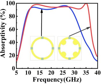
This section details the importance of the semi-circular patches at 45° apart from the central circular ring of the unit cell in broadband extension. In order to analyze, the impact of absorptivity with and without semi-circular patches is studied as depicted in Fig. 12. From the figure, the absorptivity response without the circular patches is presented in the blue color line, showing absorptivity >90% from 10.43 to 28.72 GHz with a bandwidth of 18.29 GHz (and 93.43% FBW). When the semi-circular patches are added, the absorptivity response is improved by tuning the outermost resonance. It shows the absorptivity >90% from 10.55 to 36.03 GHz (25.48 GHz bandwidth and 109.4% FBW). The loading of the shunt capacitance will increase the overall effective capacitance, and the Q-factor will reduce. This capacitance, C 2 enables the design to achieve broader bandwidth (see Fig. 12).
Simulated absorptivity of the proposed design with and without semi-circular patches.

Fabrication and measurement
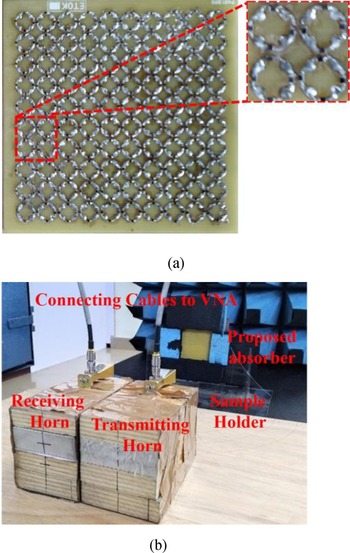
First, a 10 × 10 array (61 mm × 61 mm) of the proposed absorber is fabricated on a 0.8 mm thin single-sided FR-4 substrate using conventional printed circuit board technology, as shown in Fig. 13(a). A total of 400 chip resistors (CRCW0402200RFKED) were soldered on the prototype using surface mounting device technology. It is stacked to the copper plate with the help of double-sided adhesive tape for creating air-spacing between the top substrate and the ground. Nearly 2 mm thick adhesive tape is used, and the pressure is applied at the edges. Generally, nylon screws are used to create the air-spacer gap. Since the design has a small area, adhesive tape was used, and there is no tape in the middle. The authors believe it does not affect the overall absorption (since the 3 mm gap is left empty to the substrate for pasting with adhesive tape).
(a) Proposed fabricated prototype of 10 × 10 arrays. (b) Free-space measurement setup for the extraction of reflection and transmission properties.

The top side of the absorber is a plane dielectric surface and FSS underneath it. The reflection and transmission properties of the proposed design are measured using the free-space measurement technique, as shown in Fig. 13(b). Two broadband horn antennas (800 MHz–18 GHz, 18–40 GHz) were used for transmission and receiving over the broad measurement range. Antennas were placed at a 5° angle separation with respect to normal from the proposed design. The sample is placed at the far-field range of the antennas, which were connected to a Keysight N5224B power network analyzer (PNA). PNA calibration is performed by using a perfect electric conductor (PEC) sheet having similar dimensions as the proposed prototype. The measured reflectance of the proposed prototype is compared with the simulated one, as shown in Fig. 14. A good matching between simulated and measured results is observed with small discrepancies in the higher frequency range. These disturbances might be generated from the fabrication tolerances that exist in the design and as well as the deviation of the lumped resistance equivalence at higher frequencies. The same value of 200 Ω won't be there in the millimeter-wave range due to the additional parasitic effects of the internal series inductance and shunt capacitance between the pads of the chip resistor.
Comparison of the simulated and measured reflectances of the proposed absorber.

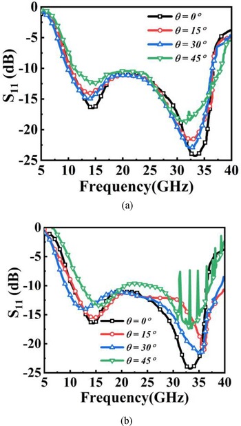
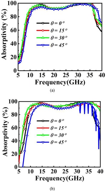
Next, the reflectance is measured for different oblique angles in TE and TM modes. Here, both the antennas were moved accordingly, and respective reflectances for different incident angles from 0 to 45° in steps of 15° are measured for TE and TM modes as detailed in [Reference Shukoor, Dey and Koul9]. The measured responses of reflectances and absorptivity for oblique incidences (TE and TM) are shown in Figs 15 and 16, respectively. To demonstrate utility of the proposed absorber in RCS reduction applications, a conventional prototype of an MSA resonating at 28 GHz is fabricated, and the RCS response is measured after loading with the absorber, which is detailed in the next section.
Measured reflectances for different oblique incidences under (a) TE and (b) TM modes.

Measured absorptivity for different oblique incidences under (a) TE and (b) TM modes.

RCS reduction analysis of the proposed absorber
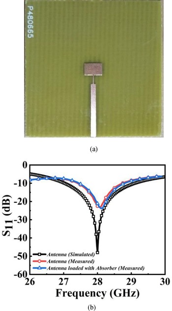
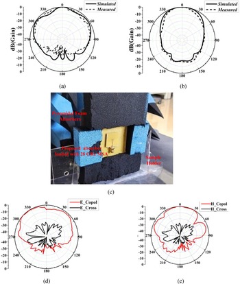
A conventional rectangular MSA is fabricated on the 0.5 mm thin FR-4 substrate where the other side is completely grounded, as shown in Fig. 17(a). The MSA resonates at 28 GHz with reflection coefficient S 11 = −47.99 dB (in simulation), and the measured reflection coefficient, S 11 = −23.25 dB at 28.05 GHz, as shown in Fig. 17(b). The radiation pattern of the antenna is measured in an anechoic chamber by placing the fabricated prototype in the vicinity of the transmitting test horn antenna. Next, the prototype antenna is stacked with the absorber with adhesive tape and the measured reflectances are given in Fig. 17(b). The radiation pattern of the antenna in both E- and H-planes is measured, and it is compared with the simulated one in Figs 18(a) and 18(b), respectively. A slight shift is observed in the reflectance of the absorber with and without the antenna due to the variation of permittivity in the surrounding medium. The configuration of the 28 GHz antenna stacked on the top of the proposed design is shown in Fig. 18(c). Fig. 18(d) and 18(e) show the measured radiation pattern of the MSA after loading with the absorber. The change in the radiation pattern is observed due to a reduction in the back-lobe level after loading with the absorber. Since the absorber is not acting as a reflectior, it is clear that there won't be any effect on the gain, directivity, and radiation efficiency. But the front-to-back ratio of the 28 GHz MSA is improved. It can be observed from Fig. 18(d) and 18(e).
(a) Fabricated prototype of the 28 GHz MSA. (b) Comparison of the simulated and measured reflectances.

Radiation pattern of the designed antenna for the E-plane (a) simulated and measured co-polarization. For the H-plane (b) simulated and measured co-polarization, (c) antenna loaded with absorber for the measurement of the radiation pattern. Measured (d) E-plane and (e) H-plane radiation patterns after loading with the absorber.

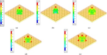
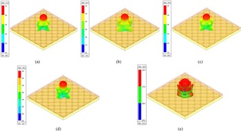
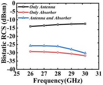
In military and defense applications, RCS reduction of the metallic object is the key problem that leads to Electromagnetic Interferences (EMI) issues between different communication devices involved. Metamaterial absorbers would be a promising solution for these kinds of problems. In order to demonstrate the utility of the broadband absorber in RCS reduction, the prototype antenna is stacked with the adhesive tape on the top of the broadband absorber (see Fig. 18(c)), and the bistatic RCS analysis is performed as detailed in [Reference Li Cong, Yu Cao, Song, Gao and Xiang Lan17]. First, the RCS pattern of the proposed absorber (6 × 6 array) is simulated, and its three-dimensional (3D) RCS characteristics at different frequencies in the desired frequency range are investigated, as depicted in Fig. 19 (for monostatic case) and in Fig. 20 (for bistatic case). The bistatic RCS of the proposed absorber array, 28 GHz MSA, and combination of both (antenna stacked on top of the top substrate) is analyzed at different frequencies (26–30 GHz in steps of 1 GHz), and the summary of the RCS obtained is presented in Fig. 21. The figure shows that the proposed design offers a relative RCS of 12–17 dB over the broad range. A slight deviation of 2.7–3.5 dB is observed in the RCS after loading the antenna in the desired operating range. The measured response of the bistatic RCS after stacking with the absorber for different oblique incidences at 28 GHz is shown in Fig. 22. It is noted that the proposed design shows a 15.15 dBsm RCS reduction of the 28 GHz MSA in comparison with PEC at normal incidence and up to 6 dBsm for 60° incident angle for TE polarization. The above performance shows that the proposed absorber is suitable for reducing RCS stealth technology and RF energy harvesting applications. The performance of the proposed absorber is compared with different broadband absorbers reported in the literature, as tabulated in Table 1. The authors strongly believe that this design is suitable to be used in real-time applications.
Simulated monostatic 3D RCS pattern of the proposed absorber (6 × 6 array) at (a) 26 GHz, (b) 27 GHz, (c) 28 GHz, (d) 29 GHz, and (e) 30 GHz.

Simulated bistatic 3D RCS pattern of the proposed absorber (6 × 6 array) at (a) 26 GHz, (b) 27 GHz, (c) 28 GHz, (d) 29 GHz, and (e) 30 GHz.

Measured bistatic RCS reduction of the proposed design loaded with the antenna referring to PEC at different frequencies.

Measured bistatic RCS of antenna loaded with the absorber for different angles of incidences at 28 GHz.

Performance comparison of the proposed design with other recently reported state-of-the-art broadband absorber designs

Here, λL is a free-space wavelength corresponding to the lowest frequency of the band.
Conclusion
A novel broadband CAA is proposed by compromising the effective permittivity surrounding the proposed FSS for broader bandwidth, and better angular stability is demonstrated. The prototype is fabricated, and the measured response is matched with the simulated one. The transmission-line circuit equivalent shows a good match with the EM simulator response. The design exhibits considerable angular stability up to 45° for TE and TM incidences. The RCS reduction of the proposed prototype is proved by placing the 28 GHz MSA on its surface, and up to 15.2 dBsm reductions are achieved at 28 GHz under normal incidence.
Acknowledgement
This study was supported by Science and Engineering Research Board (SERB), Govt. of India under project no. ECR/2018/002258.
 Mohammad Abdul Shukoor (graduate student member, IEEE) received his bachelor's degree (B.Tech) in Electronics and Communication Engineering Department from the RVR & JC College of Engineering, Guntur, India, in 2013, his master's degree (M.Tech) in radar and microwave engineering from Andhra University, Visakhapatnam, India, in 2016. He is currently working toward his Ph.D. degree with the Department of Electrical Engineering, Indian Institute of Technology Palakkad, Palakkad, India. His current research interests include metamaterial-based absorbers, FSSs, and polarization converters. He has published more than 10 research articles and filed two Indian patents. Abdul Shukoor was the recipient of the Best Paper Award in IEEE International IoT, Electronics and Mechatronics Conference, Vancouver, BC, Canada, in 2020.
 Sukomal Dey (senior member, IEEE) received his B.Tech degree in Electronics and Communication Engineering from the West Bengal University of Technology, Kolkata, India, in 2006, his M.Tech degree in Mechatronics Engineering from the Indian Institute of Engineering Science and Technology, Shibpur, India, and completed his M.Tech dissertation (1 year) at Central Electronics Engineering Research Institute (CEERI-CSIR), Pilani, India, in 2009. Dr. Dey obtained his Ph.D. degree from the Centre for Applied Research in Electronics (CARE), Indian Institute of Technology Delhi in July 2015. From August 2015 to July 2016, he was working as a project scientist in Industrial Research and Development Centre, IIT Delhi. He also worked on a collaborative research project supported by Synergy Microwave Corp., NJ, USA during the same period. From August 2016 to June 2018, he was working in the Radio Frequency Microsystem Lab (RFML), National Tsing Hua University, Taiwan, as a Post-doctorate Research Fellow. Since June 2018 he has been working as an Assistant Professor at the Department of Electrical Engineering, Indian Institute of Technology Palakkad, Kerala. Dr. Dey is a recipient of the Postgraduate Student Award from the Institute of Smart Structure and System, Bangalore in 2012, Best Industry Relevant Ph.D. Thesis Award from the Foundation for Innovation in Technology Transfer, IIT Delhi in 2016, Postdoctoral Fellow Scholarships from the Ministry of Science and Technology, Taiwan in 2016 and 2017, respectively, Early Career Research Award from the Science and Engineering Research Board (SERB), Government of India in 2019 and Smt. Ranjana Pal Memorial Award (2021) from the Institution of Electronics and Communication Engineers. He has authored/co-authored more than 80 research papers, two state-of-the art books, two book chapters, and has filed 11 patents. His research interests include electromagnetic metamaterial structures, frequency selective surfaces, microwave imaging, microwave integrated circuits including antennas, and RFMEMS.