Introduction
A robust modern economy mainly depends on low-cost, sustainable energy. Currently, the world’s energy supply is primarily centered on non-renewable fossil fuels.Reference Goodenough, Abruña and Buchanan1 The energy dilemma facing the world is twofold: global warming from greenhouse gas (CO2) emission and vulnerability from dependence on depleted supplies of oil. It is projected that world energy consumption will double within the next 50 years, concomitant with worldwide oil production, which will level off in the near future. Moreover, changes in the global economical and political situation inevitably add uncertainty and stress to the world energy supply. An urgent need therefore exists for systematic technological breakthroughs and developments emphasizing energy generation and utilization in order to reduce our reliance upon fossil fuels and to protect the environment. Recently, scientists at Lawrence Livermore National Laboratory published a report on energy consumption that showed that the transportation sector used 71% of the overall petroleum consumed in 2008 in the United States.2 Because of similar concerns, a worldwide effort has been devoted to developing advanced energy storage technologies for electrification of the transportation system, with the goal of significantly reducing the consumption of fossil fuels. In addition, the development of a low-cost and reliable battery system is critical to enable the utilization of renewable energy sources such as solar and wind energy, whose production period (mostly day time) is separate from the peak consumption period (mostly night time).
After a decade of research, several lithium-ion couples, such as graphite/nano-LiFePO4, nano-Li4Ti5O12/Li1+xMn2–xO4, and graphite/Li1+xMn2–xO4,Reference Chung, Bloking and Chiang3, Reference Amine, Belharouak, Chen, Tran, Yumoto, Ota, Myung and Sun4 have been reported to meet the requirements for hybrid electric vehicles (HEV).5 All of these technologies offer high power but limited energy densities, making them inadequate to power pure electric vehicles (EVs) or plug-in hybrid electric vehicles (PHEVs) with an electric drive range of 40 miles. Alternatively, cathode materials made of lithium-rich transition metal oxides with composite structures (xLi2MnO3•(1–x)LiMO2, M is a transition metal or a mixture of transition metals)Reference Kim, Johnson, Vaughey, Thackeray and Hackney6, Reference Deng, Belharouak, Cook, Wu, Sun and Amine7 or lithium-rich cathodes (Li1+xM1–xO2, M is a transition metal or a mixture of transition metals)Reference Lu, MacNeil and Dahn8, Reference Lu and Dahn9 offer both higher specific capacity (>200 mAhg–1) and higher working potential (>4.3 V versus Li+/Li). In exchange for their high-energy densities, however, these cathode materials, still in the process of development, require more work to increase their tap density—the amount of material that can be loaded in a specific volume—and to improve their power performance. In addition, this class of materials exhibits capacity fade (or gradually reducing capability to store energy) during cycling or storage at elevated temperatures due to the chemical reaction between the delithiated cathode and the electrolyte at high operating voltage. To overcome the performance degradation of cathode materials and increase their capacity retention when operated at high voltage, several research groups have developed various approaches such as AlF3 nanocoatings at the particle level in cathodes,Reference Sun, Han, Myung, Lee and Amine10–Reference Zheng, Zhang, Wu, Dong, Zhu and Yang19 core-shell structures,Reference Sun, Myung, Kim, Prakash and Amine20–Reference Wang, Feygenson, Aronson and Han30 and a concentration-gradient material.Reference Sun, Myung, Park, Prakash, Belharouak and Amine31–Reference Sun, Lee, Noh, Wu, Myung and Amine34All of these materials show higher capacities than conventional cathode materials such as LiCoO2, with further benefits of improved cycling performance and better capacity retention during high temperature storage. In addition, these materials also have higher tolerance to thermal abuse, which is highly desired to ensure safe operation of batteries in a large scale format.
Process to synthesize dense and spherical materials
Many reported processes have been developed to synthesize lithium transition metal oxides, including a sol-gel process,Reference Bhuwaneswari, Dimesso and Jaegermann35–Reference Soltanmohammad and Asgari37 spray drying,Reference Nakahara, Nakajima, Matsushima and Majima38–Reference Yu, Zhang, Yang and Song40 hydroxide-based co-precipitation,Reference Sun, Myung, Kim, Prakash and Amine20–Reference Yang, Cao, Liu, Chen and Jiao26, Reference Lee, Kang, Myung and Sun41–Reference Kim, Myung, Bang, Prakash and Sun45 and carbonate-based co-precipitation.Reference Deng, Belharouak, Cook, Wu, Sun and Amine7, Reference Park, Shin, Myung, Yoon, Amine and Sun44 In practice, a high tap density of active electrode materials is highly desired so that more active material can be packed into a specific volume to store more energy. The hydroxide process has been successfully deployed to synthesize a dense and spherical precursor; the spherical morphology is beneficial to reduce the specific surface area of the cathode material that is directly exposed to non-aqueous electrolytes. A small specific surface area is beneficial to minimize the active site for the reaction between the charged cathode material and the electrolyte, and therefore greater stability can be expected. Furthermore, a spherical morphology is preferred for nanoscale coatings and allows for easy and uniform electrode processing.
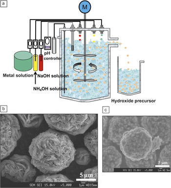
Figure 1a shows a schematic drawing of the continuous stirred tank reactor used in the hydroxide process.Reference Sun, Lee, Noh, Wu, Myung and Amine34 This apparatus can also be used for the carbonate process by changing the precipitation agent from ammonium hydroxide solution to Na2CO3 or another carbonate source. The continuous reactor has feedback control for both the temperature and pH of the reaction medium and, therefore, has the capability to control the kinetics of particle growth, leading to ideal spherical morphology. Three stock solutions are used in this design: a mixture of the desired transition metal salt dissolved in water, an ammonium solution used as the precipitation agent for the transition metal source, and a NaOH solution used for pH control. The feed rate of the stock solutions can be adjusted to vary the retention time of particles in the reactor tank, providing control of the particle size in the final material. Figure 1b shows a typical scanning electron microscope image of transition metal hydroxides (Ni1/3Co1/3Mn1/3(OH)2) prepared in the continuous stirred tank reactor. After calcination in the presence of a lithium source such as LiOH•H2O, the spherical morphology of the metal hydroxide precursor was retained (see Figure 1c).
(a) Schematic drawing of a continuous stirred tank reactor to prepare dense and spherical transition metal hydroxides for synthesis of advanced cathode materials with high tape density; M, motor; (b) scanning electron micrograph of spherical Ni1/3Co1/3Mn1/3(OH)2 precursor prepared using the continuous reactor; Reference Sun, Lee, Noh, Wu, Myung and Amine34 and (c) scanning electron micrograph of calcined materials (LiNi1/3Mn1/3Co1/3O2) showing the preservation of particle morphology after calcination.Reference Lim, Bang, Lee, Amine and Sun43

AlF3 coating
A lithium-ion battery is sensitive to the operation/storage temperature and its upper cutoff voltage during charge/discharge cycles. To maintain optimal performance, lithium-ion batteries are generally operated below a specific working potential, such as 4.2 V, above which the electrochemical performance suffers greatly.Reference Chen, Qin, Amine and Sun46 Similar accelerated performance degradation is also widely observed at elevated temperatures, such as 55°C.Reference Chen, Qin, Amine and Sun46, Reference Sun, Hong, Prakash and Amine47 The performance degradation of lithium-ion batteries is thought to partially result from chemical corrosion of the lithium transition metal oxide cathode in the acidic electrolyte. Although a nonaqueous electrolyte is required for lithium-ion batteries, a trace amount of moisture in the range of 20 ppm (parts per million) to 100 ppm can still be detected in battery-grade electrolytes. This small amount of moisture tends to react with the main salt (LiPF6) and generate HF, as shown in the following equation:

The HF will then slowly corrode the cathode material, causing slow dissolution of the transition metal ion into the electrolyte and migration of this ion to the anode.Reference Akimoto, Takahashi and Kijima48, Reference Amine, Liu, Belharouak, Kang, Bloom, Vissers and Henriksen49 Furthermore, at high voltages, the electrolyte can be easily oxidized because of the high surface oxidation capability of the delithiated oxide.Reference Lu, Chen, Joachin, Prakash, Liu and Amine50, Reference Chen, Qin, Liu and Amine51
Several surface coating techniques have been widely used to extend the cycle life of lithium transition metal oxide cathodes and to increase their capacity by operating at a higher voltage.Reference Sun, Hong, Prakash and Amine47, Reference Mladenov, Stoyanova, Zhecheva and Vassilev52–Reference Hwang, Chen, Cheng, Santhanam and Ragavendran61 Early efforts were mostly concentrated on metal oxide coatingsReference Sun, Hong, Prakash and Amine47, Reference Cho, Kim and Yoo53–Reference Han, Myung and Sun56, Reference Myung, Izumi, Komaba, Yashiro, Bang, Sun and Kumagai60, Reference Hwang, Chen, Cheng, Santhanam and Ragavendran61 as an HF scavenger to reduce the local acidity (or H+ concentration) on the surface of cathode materials:

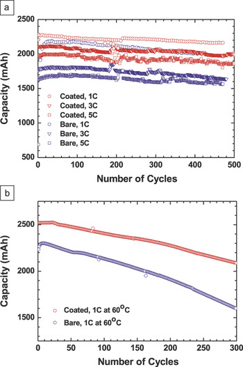
In Equation 2, M stands for a metal element such as Al, Mg, Zr, or Zn, and x is one half of the valence state of M. The metal-oxide coating has been consistently demonstrated to improve the capacity retention of cathode materials.Reference Sun, Hong, Prakash and Amine47, Reference Cho, Kim and Yoo53–Reference Myung, Izumi, Komaba, Sun, Yashiro and Kumagai55, Reference Myung, Izumi, Komaba, Yashiro, Bang, Sun and Kumagai60, Reference Hwang, Chen, Cheng, Santhanam and Ragavendran61 As a typical example of the beneficial effect of Al2O3 on the surface of cathode materials, Figure 2 shows the discharge capacity of bare and Al2O3-coated (0.25 wt%) Li[Li0.05Ni0.4Co0.15Mn0.4]O2/C cells at 25°C and 60°C.Reference Myung, Izumi, Komaba, Sun, Yashiro and Kumagai55
Cyclability of bare and Al2O3-coated (0.25 wt%) Li(Li0.05Ni0.4Co0.15Mn0.4)O2/C cells at (a) 25°C and (b) 60°C, showing the positive effect of an Al2O3 coating on extending cycle life.Reference Myung, Izumi, Komaba, Sun, Yashiro and Kumagai55 1C means to fully charge/discharge the cell in one hour, and 3C means to fully charge/discharge in 20 minutes.

Because water is the product of the reaction between HF and the metal oxide coating (see Equation 2), it further reacts with LiPF6 and generates more HF (see Equation 1).The HF then preferably reacts with the nano-metal oxide coating, and thereby delays corrosion of the cathode material. This protection mechanism is lost once the HF completely consumes the protective oxide coating. It is doubtful that the small amount of oxide in the protective shell can persist for the extended period needed for transportation applications (10–15 years). An alternative coating approach is to use a coating that resists HF attack, such as metal fluorides. On the basis of this assumption, AlF3 was selected as an alternative protective coating of cathode materials.Reference Sun, Han, Myung, Lee and Amine10–Reference Zheng, Zhang, Wu, Dong, Zhu and Yang19 Furthermore, Al3+ does not oxidize further during cycling at high voltage, and the activation energy of breaking the Al–F bond is very high. As a result, one can expect that the AlF3 coating will remain intact on the cathode surface during extensive cycling.
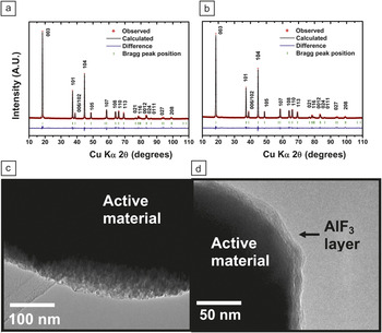
Figure 3 shows the x-ray diffraction patterns of uncoated (Figure 3a) and AlF3 coated cathode materials (Figure 3b) as well as transmission electron micrographs of uncoated (Figure 3c) and AlF3 coated (Figure 3d) materials. The particular sample in Figure 3 was a delithiated material, (Li0.35(Ni1/3Co1/3Mn1/3)O2),Reference Myung, Lee, Yoon, Sun, Amine and Yashiro16 which was first coated with AlF3 before chemical delithiation. Coating the cathode material with AlF3 involved precipitation from an aqueous solution of ammonium fluoride and aluminum nitrate. This method resulted in a uniform coating layer that was thinner than 20 nm (see Figure 3d). The x-ray diffraction patterns (Figure 3a and 3b) showed no evidence of the formation of an Al–F-related impurity in the coated material due to the poor crystallinity and the small amount of AlF3 coating. Rietveld refinement, a method that involves refining powder diffraction data to find the crystal structure, of the x-ray diffraction patterns showed no change in the lattice parameter of the cathode material with and without AlF3 coating, suggesting that the AlF3 compound is only present on the surface of the active material.
Rietveld refinement of x-ray diffraction data for the chemically delithiated (a) uncoated Li0.35(Ni1/3Co1/3Mn1/3)O2 and (b) AlF3-coated Li0.35(Ni1/3Co1/3Mn1/3)O2; corresponding transmission electron microscopy bright-field images of (c) chemically delithiated uncoated Li0.35(Ni1/3Co1/3Mn1/3)O2 and (d) AlF3 coated Li0.35(Ni1/3Co1/3Mn1/3)O2.Reference Myung, Lee, Yoon, Sun, Amine and Yashiro16

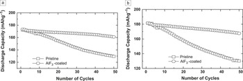
Figure 4 shows the discharge capacity of Li/pristine and AlF3-coated Li(Ni1/3Co1/3Mn1/3)O2 cells over 50 cycles in the voltage range of 3.0–4.5 V and 3.0–4.6 V at a current rate of 80 mAh·g–1 (0.5C rate, or a rate to fully charge/discharge the cell in two hours).Reference Sun, Cho, Lee, Yoon and Amine11 In the 3.0–4.5 V range, the pristine and AlF3-coated Li(Ni1/3Co1/3Mn1/3)O2 delivered the same discharge capacity of 173 mAh·g–1. The pristine Li(Ni1/3Co1/3Mn1/3)O2 showed a gradual decrease in capacity, leading to a capacity retention of 75% after 50 cycles. The AlF3-coated Li(Ni1/3Co1/3Mn1/3)O2 showed a remarkably better capacity retention of 93% for the same cycling period. Similar to the 3.0–4.5 V range, the capacity retention of AlF3-coated Li(Ni1/3Co1/3Mn1/3)O2 in the 3.0–4.6 V range significantly improved (92% capacity retention) compared to the pristine cathode (72% capacity retention).
Cycling performance of Li/pristine Li(Ni1/3Co1/3Mn1/3)O2 and Li/AlF3-coated Li(Ni1/3Co1/3Mn1/3)O2 cells cycled at (a) 3.0–4.5 V and (b) 3.0–4.6 V show the beneficial impact of the AlF3 coating on the capacity retention.Reference Sun, Cho, Lee, Yoon and Amine11

Further investigation revealed that the performance of cathode materials also greatly depends on the amount of AlF3 coating.Reference Sun, Cho, Myung, Amine and Prakash12 Overly thick coatings of AlF3 on LiCoO2 deteriorated both the capacity retention and rate capability of AlF3-coated LiCoO2Reference Sun, Cho, Lee, Yoon and Amine11 thought to be due to the high interfacial impedance of the electrode caused by the thick coating. Another possible explanation is that AlF3 is an insulator to both electrons and lithium ions, and a thicker coating lowers the kinetics of the charge-transfer reaction at the coating/active material interface. Therefore, an optimum AlF3 coating is required to achieve a performance that is a compromise between overall protection and charge-transfer kinetics.
Core-shell structured materials
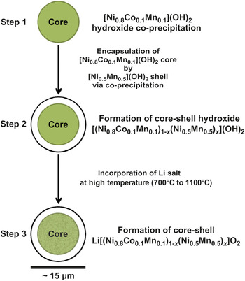
The core-shell structure is a conceptual extension of the AlF3 coating, where the AlF3 is replaced by a layer of active cathode material with better thermal stability and better compatibility toward nonaqueous electrolytes.Reference Sun, Myung, Kim, Prakash and Amine20–Reference Wang, Feygenson, Aronson and Han30 In this case, a high-capacity nickel-rich cathode material can be used as the bulk (core), and a nickel-poor composition can be used as the shell. Formation of this core-shell structure has three main steps (Figure 5). First, the nickel-rich (Ni0.8Co0.1Mn0.1)(OH)2 precursor is formed as the core, with a particle diameter of about 12–13 μm (Step 1). The core is then completely encapsulated by a nickel-poor (Ni0.5Mn0.5)(OH)2 shell with a thickness between 1 and 1.5 μm (Step 2). Finally, calcination of the core-shell hydroxide with a lithium salt generates spherical core-shell Li[(Ni0.8Co0.1Mn0.1)1–x(Ni0.5Mn0.5)x]O2 powders (Step 3).
Schematic drawing of the formation process of microscale core-shell structured Li[(Ni0.8Co0.1Mn0.1)1–x(Ni0.5Mn0.5)x]O2. Step 1: synthesis of Ni-rich [Ni0.8Co0.1Mn0.1](OH)2; Step 2: formation of core-shell [(Ni0.8Co0.1Mn0.1)1–x(Ni0.5Mn0.5)x](OH)2 hydroxide precursor; and Step 3: formation of core-shell Li[(Ni0.8Co0.1Mn0.1)1–x(Ni0.5Mn0.5)x]O2 by calcination of [(Ni0.8Co0.1Mn0.1)1–x(Ni0.5Mn0.5)x](OH)2 with lithium salt.Reference Sun, Myung, Kim, Prakash and Amine20

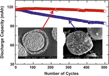
The Figure 6 inset (bottom right) shows a scanning electron microscopy image of the cross-section of the core LiNi0.8Co0.1Mn0.1O2 material, which exhibits capacity fade when operating at high voltage because of high surface reactivity toward the electrolyte. The Figure 6 inset (bottom left) shows the cross-section of the core-shell, where the core and shell are clearly visible. In this case, the core material is LiNi0.8Co0.1Mn0.1O2, and the shell is LiNi0.5Mn0.5O2. The core-shell structure takes advantage of both the high capacity of the core material and the excellent stability of the shell material. As a result, the full cell based on the core-shell cathode and a mesocarbon microbead anode shows far better capacity retention with almost no capacity fade after 500 cycles.Reference Sun, Myung, Kim, Prakash and Amine20, Reference Sun, Myung, Shin, Bae and Yoon22
Discharge capacity of lithium-ion cells using a graphite anode and two different cathodes. One of the cathodes is core-shell structured Li[(Ni0.8Co0.1Mn0.1)0.8(Ni0.5Mn0.5)0.2]O2 (red curve), and the other is LiNi0.8Co0.1Mn0.1O2 (blue curve).Reference Sun, Myung, Kim, Prakash and Amine20 The core-shell structure material has better capacity retention than the core material.

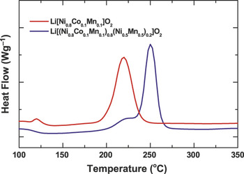
Figure 7 shows that the core-shell Li[(Ni0.8Co0.1Mn0.1)0.8(Ni0.5Mn0.5)0.2]O2 has a higher exothermic onset temperature than the core-only Li(Ni0.8Co0.1Mn0.1)O2 electrode. A high onset temperature here generally means higher thermal stability, or, in other words, thermal decomposition of the cathode material will be triggered at a higher temperature. For the Li(Ni0.8Co0.1Mn0.1)O2 electrode, the onset temperature of the exothermic peak was about 180°C, above which an abrupt exothermic reaction occurred with an enthalpy of 3285 Jg–1 at about 220°C. However, core-shell Li[(Ni0.8Co0.1Mn0.1)0.8(Ni0.5Mn0.5)0.2]O2 showed an exothermic reaction at 250°C with a reduced enthalpy of 2261 Jg–1 when compared to the Li(Ni0.8Co0.1Mn0.1)O2 core electrode. As previously reported, the exothermic reaction of Li(Ni0.5Mn0.5)O2 occurs at about 270–280°C,with an even lower heat flow.Reference Kang, Kim, Stoll, Abraham, Sun and Amine62 The thermally stable outer Li(Ni0.5Mn0.5)O2 shell is believed to suppress the oxygen release from the highly delithiated Li1–x(Ni0.8Co0.1Mn0.1)O2, thereby improving the thermal stability of the Li[(Ni0.8Co0.1Mn0.1)0.8(Ni0.5Mn0.5)0.2]O2 core-shell.
Differential scanning calorimetry traces of Li[(Ni0.8Co0.1Mn0.1)0.8(Ni0.5Mn0.5)0.2]O2 and Li[Ni0.8Co0.1Mn0.1]O2 charged to 4.3 V show that the core-shell structure material has better thermal stability than the core material.Reference Sun, Myung, Kim, Prakash and Amine20

While the core-shell approach improves the electrochemical performance and thermal stability of cathodes, the long-term cyclability of this material is still questionable. Voids of tens of nanometers between the core and the shell of core-shell-structured materials develop during cell testing because of the crystal structure mismatch during cycling.Reference Sun, Myung, Park, Prakash, Belharouak and Amine31 The core material (LiNi0.8Co0.1Mn0.1O2) tends to shrink by approximately 9–10% in volume, while the shell material (LiNi0.5Mn0.5O2) only shrinks by about 3 vol% during cycling. Repeated charge/discharge cycling can cause mechanical stress at the interface between the core and the shell. This stress can lead to fatigue of the material and separation between the core and the shell material, resulting in a significant rise in cell impedance.
Concentration-gradient materials
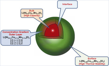
To avoid cracks between the core material and the shell material in the core/shell structure, Sun and AmineReference Sun, Myung, Park, Prakash, Belharouak and Amine31–Reference Sun, Lee, Noh, Wu, Myung and Amine34 reported a novel high-capacity and safe cathode material with Ni-rich layered oxides, in which each particle consists of bulk material surrounded by a concentration-gradient outer layer. As illustrated in Figure 8, as one example,Reference Sun, Myung, Park, Prakash, Belharouak and Amine31 the bulk is a nickel-rich layered oxide (Li[Ni0.8Co0.1Mn0.1]O2) to satisfy the need for high energy density. In the outer layer, the reactive nickel ions are gradually replaced with manganese ions when moving outward to provide better stability against the electrolyte and improve cycle life and safety. The resulting surface composition is Li[Ni0.46Co0.23Mn0.31]O2, which is much more stable when in contact with the electrolyte than is the bulk composition.
Schematic diagram of a cathode particle with a Ni-rich core surrounded by a concentration-gradient outer layer.Reference Sun, Myung, Park, Prakash, Belharouak and Amine31

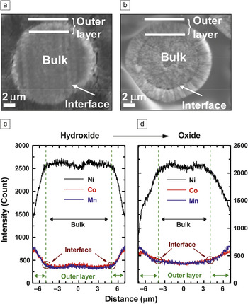
This concentration gradient was prepared by first making a concentration-gradient hydroxide precursor. The core of the precursor, (Ni0.8Co0.1Mn0.1)(OH)2, was synthesized with a co-precipitation method using NiSO4•6H2O, CoSO4•7H2O, and MnSO4•5H2O (8:1:1 in molar ratio) as starting materials. During the reaction, a Ni-poor aqueous solution (Ni:Co:Mn = 0.08:0.46:0.46 in molar ratio) was pumped into a Ni-rich (Ni:Co:Mn = 0.8:0.1:0.1 in molar ratio) solution tank, after which the homogeneously mixed solution was fed into a continuously stirred tank reactor. The obtained particles were filtered, washed with deionized water, and dried at 25°C to remove adsorbed water in a vacuum. Figure 9 shows cross-sectional scanning electron microscope images and electron probe x-ray microanalysis (EPMA) results of the precursor (Figure 9a and 9c) and concentration-gradient materials (Figure 9b and 9d). The EPMA examination (Figure 9d) showed that the concentration-gradient layer was maintained after calcination, even though the concentration-gradient change of transition metals is less steep than in the case of the hydroxide precursor due to inter-diffusion of metal ions during the high-temperature calcination process.
Scanning electron micrograph (a) and electron probe microanalysis (EPMA) line scan (c) of precursor hydroxide; scanning electron micrograph (b) and EPMA line scan (d) of final lithiated oxide Li[Ni0.64Co0.18Mn0.18]O2. In both materials, the gradual concentration changes of Ni, Mn, and Co in the interlayer are clearly evident. The Ni concentration decreases, and the Co and Mn concentrations increase toward the surface.Reference Sun, Myung, Park, Prakash, Belharouak and Amine31

Figure 10a shows the capacity retention of half cells using Li(Ni0.8Co0.1Mn0.1)O2, Li(Ni0.46Co0.23Mn0.31)O2, and the concentration-gradient Li(Ni0.64Co0.18Mn0.18)O2.The cells were charged to 4.4 V and cycled at 55°C. Cells based on both Li(Ni0.8Co0.1Mn0.1)O2 and the concentration-gradient material show a high initial capacity of approximately 209 mAhg–1, which would meet the energy requirement needed for PHEVs. However, the cell based on the bulk Li(Ni0.8Co0.1Mn0.1)O2 composition retained only 67% of its initial capacity after 50 cycles, whereas the concentration-gradient material showed an excellent capacity retention of 96% during the same cycling period. The capacity retention of the concentration-gradient material is similar to that of the cell based only on the surface composition, Li(Ni0.46Co0.23Mn0.31)O2.This result clearly indicates that the concentration-gradient approach can create a composite material that takes advantage of the high energy density of the core and the better stability of the shell.
(a) Cycling performance of half cells based on Li[Ni0.8Co0.1Mn0.1]O2, Li[Ni0.46Co0.23Mn0.31]O2, and concentration-gradient material (Li[Ni0.64Co0.18Mn0.18]O2) cycled between 3.0 and 4.4 V at 55°C by applying a constant current of 95 mAg–1 (0.5C-rate); (b) differential scanning calorimetry traces showing heat flow from the reaction of the electrolyte with concentration-gradient Li1–x[Ni0.8Co0.1Mn0.1]O2, Li1–x[Ni0.64Co0.18Mn0.18]O2 and Li1–x[Ni0.46Co0.23Mn0.31]O2 charged to 4.3 V. Reference Sun, Myung, Park, Prakash, Belharouak and Amine31

Figure 10b shows the differential scanning calorimetry profiles of Li1–x(Ni0.8Co0.1Mn0.1)O2 and the concentration-gradient Li1–x(Ni0.64Co0.18Mn0.18)O2 charged to 4.3 V in the presence of a commonly used electrolyte, 1.0 M LiPF6/ethylene carbonate–diethyl carbonate. For Li1–x(Ni0.8Co0.1Mn0.1)O2, the onset temperature of the exothermic reaction occurred at approximately 180°C, with a peak at 220°C.The concentration-gradient material exhibits a higher onset temperature compared with the bulk composition Li(Ni0.8Co0.1Mn0.1)O2.The stability of this material may originate from the Mn4+ in the surface region. The onset temperature of the exothermic reaction was 270°C for the concentration-gradient Li1–x(Ni0.64Co0.18Mn0.18)O2; thus, the reaction with the electrolyte was delayed by approximately 90°C compared with Li1–x(Ni0.8Co0.1Mn0.1)O2, owing to the high stability of the outer surface composition Li1–x(Ni0.46Co0.23Mn0.31)O2 in the concentration-gradient material, which shows an onset temperature of over 305°C.
Conclusions
The energy density of cathode materials for lithium-ion batteries can be greatly increased by increasing the Ni content, but this increase leads to deteriorated electrochemical and thermal stability of materials in the charged state due to the instability of tetravalent nickel in the oxide phase. Thus, developing cathode materials with high energy density and good stability for transportation applications is a major challenge. As summarized here, this challenge can be mitigated by surface coatings, including strategies such as coating with a thin metal fluoride layer, creating a core-shell structure, and designing concentration-gradient materials. Because of lattice mismatch during charge/discharge cycles, materials with the core-shell structure commonly suffer from mechanical stress between the core and the shell, potentially leading to possible separation at the interface with negative consequences for charge-carrier mobility into the active core. Alternatively, materials designed with a concentration-gradient have better mechanical stability because of the gradual change in the composition, which suppresses lattice mismatch across the particles during charge/discharge cycling. In addition, a common advantage of these surface coating techniques is that the coating layer is inert or less reactive toward non-aqueous electrolytes, resulting in an improvement in the electrochemical performance and the thermal stability of the cathode material.
Acknowledgments
The research of Z. Chen and K. Amine is funded by the U.S. Department of Energy, FreedomCAR, and Vehicle Technologies Office. Argonne National Laboratory is operated for the U.S. Department of Energy by the UChicago Argonne, LLC, under contract DE-AC02-06CH11357. The work of D.-J. Lee and Y.-K. Sun was supported by the Basic Science Research Program through the National Research Foundation of Korea (NRF) grant funded from the Ministry of Education, Science and Technology (MEST) of Korea for the Center for Next Generation Dye-sensitized Solar Cells (No. 2010-0001842) and by the Human Resources Development of the Korea Institute of Energy Technology Evaluation and Planning (KETEP) grant funded by the Korea government Ministry of Knowledge Economy (No. 20104010100560).