1. INTRODUCTION
Vertical reference for hydrographic survey can be provided in two ways: through the use of an expensive and very accurate GPS-aided INS system, or through the classical method of compensating for heave motion measured on board the vessel and tide data taken from a nearby tide gauge. Whilst the GPS-aided INS approach offers significant advantages in terms of accuracy their high cost has prohibited their widespread use within the hydrographic survey industry and the classical method is still prevalent.
Heave motion of a survey vessel has traditionally been measured using inertial technologies, which can be expensive and have problems with usability and instability, resulting in higher survey costs and a significant hydrographer input burden. Heave can also be measured through the use of GPS receivers by the differencing of measured carrier phase observable from adjacent epochs. The recent introduction by U-Blox of the Antaris AEK-4T, an off the shelf low cost GPS receiver capable of measuring and recording the carrier phase observable, has allowed the exploration of a novel method of measuring and compensating for vessel heave using off the shelf low cost GPS receivers.
The technique is based on the production of highly accurate velocity estimates using the carrier phase observable. Carrier phase measurements are differenced across adjacent epochs to give relative delta range estimates between receiver and satellite along the direct line of sight, which are then processed to calculate an accurate estimate of receiver delta position across the epoch, a measurement analogous to receiver velocity. This technique has been termed Temporal Double Differencing (TDD). Integrated vertical velocity estimates produce the relative vertical displacement of the vessel over time. Because of bias errors in the velocity estimates from TDD, this vertical displacement is subject to drift. The drift is removed by passing the data through a high-pass filter designed to stop the drift frequencies yet pass the required frequencies of vertical vessel motion.
An obvious advantage of this technique over conventional technologies is cost. Instruments currently on the market are centred on inertial sensors and generally have prices ranging from £12,000 to £25,000. Low cost GPS receivers are priced at around £200 and so this technique can have sizeable cost implications for the hydrographic survey industry. In addition the nature of the TDD algorithm results in a heave sensing technology that is not subject to turn induced heave which can affect inertial based sensors, and also imposes no requirement on the user to account for parameters such as vessel heave characteristics and current heave state. A further advantage over interferometric GPS heave compensation techniques is that the TDD algorithm is stand-alone and requires no reference receiver.
2. THE TDD VELOCITY ALGORITHM
The estimation of velocity from GPS can be undertaken using various methods. The method used to produce the GPS based heave algorithm developed as part of this project is time differenced carrier phase observable (Itani et al., Reference Itani, Hayashi and Ueno2000; Serrano et al., Reference Serrano, Donghyun, Langley, Itani and Ueno2004; van Graas and Soloviev, Reference van Graas and Soloviev2004), a method often referred to as temporal differencing. This is currently the most accurate velocity estimation method to utilize only a single, stand-alone, GPS receiver because it is based on the carrier phase observable which contains less noise than the pseudo-range rate observable.
Derivation of the TDD observation equation begins with the carrier phase observation equation with time frames removed for increased clarity of the TDD concept.

The first difference, that between observations from a single satellite recorded at adjacent epochs, results in the removal of the integer ambiguity term, N s from 1.
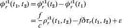
Equation 2 describes the single differenced observations taken across two epochs. The integer ambiguity term, N s, has been differenced and the change in range and receiver clock drift terms remain. The tropospheric delay is compensated for using STANAG (1990) and ionospheric delay compensation is either by Klobuchar (Reference Klobuchar1996) in the case of single frequency receivers or using the ionospherically free observable. The satellite clock drift term is calculable from the GPS navigation message and is considered known.
The second difference occurs between two single difference equations generated from observations from separate satellites:
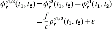
In Equation 3 the receiver clock drift term, δτr (t 1,t 2), is differenced away and ε is a combined error term that covers all remaining satellite, receiver and multipath errors.
The majority of cycle slips that may occur in the measurement of the carrier phase observable are handled inherently as part of the TDD algorithm itself by virtue of the fact that two consecutive epochs of data are required from each satellite. When, in the case of a particular satellite, there were not consecutive observations, that satellite's data was discarded and not included in the algorithm. In addition to the cycle slip immunity offered by the TDD velocity algorithm, a process of least squares analysis was developed that would remove any ‘bad’ observations that have been subject to slips and have introduced an error in the TDD velocity estimation.
The use of the U-Blox Antaris low cost receiver in this paper necessitated the development of a weighting scheme to better handle the raw carrier phase observables. Weighting schemes have been suggested based upon both satellite elevation angle and observation signal-to-noise ratio (Collins and Langley, Reference Collins and Langley1999) but analysis of the stand-alone position and TDD velocity residuals from the least squares estimation using the U-Blox receiver suggested a strong correlation between poor quality observations and carrier-to-noise density, C/N0. For this reason, and because they are considered to be potentially more powerful, it was decided to employ a weighting scheme based upon the carrier-to-noise density of each observation. Collins and Langley (Reference Collins and Langley1999) implemented a weighting scheme based upon the approximation of the formula for calculating carrier tracking loop noise given in Langley (Reference Serrano, Donghyun, Langley, Itani and Ueno1997) :
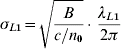
where σL1 is the error on the carrier phase measurement (m), B is the carrier tracking loop bandwidth (Hz), c/n 0 is the carrier-to-noise density expressed as a ratio (= in dB-Hz) and λL1 is the L1 carrier wavelength.
To be able to implement this formula as a weighting scheme it was required that the carrier-to-noise density be recorded by the receiver to be used. The U-Blox Antaris receiver does record this value and, using Equation 4, a function was arrived at that would provide the weighting scheme for the U-Blox Antaris GPS observations. The calculated weighting factors were then formed into a weighting matrix for inclusion in the TDD velocity least squares estimation.
3. HEAVE FROM TDD VELOCITY
The velocities produced by the TDD velocity algorithm were integrated in the vertical channel in order to produce relative vertical position, which could be directly compared to the heave output from an inertial based heave sensor. Bias errors in the vertical velocity resulted in a drift of the relative vertical position with time, however, and these drift errors had to be removed to improve the accuracy of the TDD heave algorithm output.
A high pass filter was designed that removed all the drift yet left a zero-meaned relative vertical position output within the required heave frequency band (>0·03 Hz). The filter has a -3dB cut-off frequency of 0·03 Hz and is a linear phase finite impulse response filter designed using the Parks-McClellan algorithm (IEEE, 1979) within the filter design and analysis tool in Matlab. The order of the filter was 276 and it imparted a group delay of 138 seconds. The order of the filter was not considered an important factor when designing the heave filter as the TDD heave algorithm was always intended to be a near real time system. Increasing the performance of the filter in terms of its design criteria would have the effect of increasing the filter order and, hence, the filter group delay.
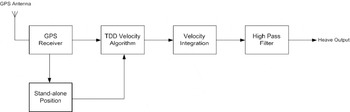
The heave filter designed was used to remove all the drift from the relative position output gained from the integration of the TDD velocities and the bias errors associated with it. A block schematic diagram of the full TDD heave algorithm is included in Figure 1 showing the entire process from raw GPS data collection through to heave output.
Block schematic diagram of the TDD heave algorithm.

4. SPIRENT SIMULATOR TRIAL
The IESSG has purchased a highly versatile piece of test equipment, a Spirent GSS7700 GPS/SBAS Simulator, that can simulate the entire GPS constellation and generate signals that can be fed directly into a GPS receiver. The Spirent simulator simulates the GPS signals transmitted by each of the GPS satellites as they would be received by a GPS receiver that was undergoing the dynamics laid out in the simulator scenario. As such, the Spirent simulator provides an excellent platform from which to test different GPS receivers against one another.
A trial was developed to assess the quality of the phase pseudo-range observable recorded with a commercially available low cost GPS receiver, and its ability to be used to estimate receiver velocity using the TDD velocity algorithm. The TDD velocity algorithm has been tested using three separate GPS receivers: one low cost and two dual frequency. They have each been used to collect simulated raw GPS observables under varying simulated dynamic conditions and the use of the Spirent simulator allowed the extraction of truth data that meant a highly accurate assessment of receiver performance was possible.
The simulator trial was designed to test both the TDD velocity and heave algorithms developed as part of the project, and the effect of the use of low cost receivers compared to geodetic grade receivers. With this in mind three separate GPS receivers were selected for the trials that represented a range of grades:
• Leica 530 Dual Frequency Receiver
• NovAtel OEM4 Dual Frequency Receiver
• UBlox Antaris LEA4T Single Frequency Receiver
Two scenarios were used to test each receiver under different dynamic conditions and also demonstrate the operability and limitations of the TDD velocity and heave algorithms. An arbitrary date of 24 January 2006 was selected to be the trial date for all simulator trials and the ephemeris data for that date, downloaded from National Geodetic Survey (Reference Serrano, Donghyun, Langley, Itani and Ueno2007), was loaded into each of the three scenarios.
5. SIMULATED STATIC SCENARIO
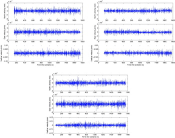
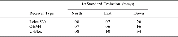
A static scenario was first run that simulated a static GPS receiver at the same location as a real GPS antenna sited on the turret of the IESSG building. Static GPS data simulated by the Spirent simulator was collected using the three GPS receivers. The raw data collected were then converted into RINEX v2.1 files ready for processing through the TDD velocity algorithm. The velocities output by the algorithm are shown in Figure 2 for Leica 530, (Top left), NovAtel OEM4 (Top Right) and U-Blox Antaris (Bottom) respectively. The data collected was from a static scenario and the plots of TDD velocity can therefore also be considered error plots. The error can be shown to be normally distributed and so the standard deviation of the error is presented in Table 1; the mean of the error experienced during the static scenario was at the micrometre or tens of micrometre level and so was considered negligible and not included in the results of Table 1.
The TDD velocity from simulated static for the Leica 530 dual frequency receiver (Top left), NovAtel OEM4 dual frequency receiver (Top right) and U-Blox Antaris single frequency receiver (Bottom).

Results of static test of TDD velocity algorithm using error free simulated data.
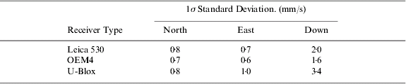
Table 1 shows that the U-Blox receiver performed to the same standard as both the dual frequency receivers when in a static environment. The figures presented in the table show standard deviation and mean error values for the U-Blox receiver of the same order as for the Leica and the NovAtel. These results were slightly unexpected considering the difference in cost between the receivers but were thought to probably be an artefact of the tracking loop algorithms employed in the U-Blox receiver. It is accepted that the Leica and NovAtel will most likely utilize higher grade components within the receiver, but when static the U-Blox receiver may use the lack of dynamics to alter the bandwidth of its tracking loops. This analysis is largely conjecture but it is certainly safe to say from these results that, under static error free conditions, the U-Blox receiver can perform at least as well as the Leica and NovAtel receivers.
6. SIMULATED MARINE SCENARIO
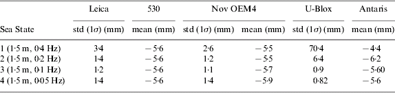
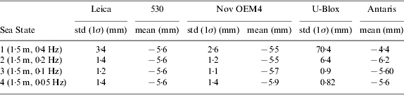
A marine scenario was developed that was intended to deliver the most realistic simulation of the intended heave algorithm environment. The motion file for the marine scenario held the vessel static, in the same position as simulated for the static scenario, for a period of 650 s so that each of the GPS receivers used would have suficient time to lock on to all the satellites before simulated motion began. The scenario then took the simulated vessel from the start position in a straight line in a north-westerly direction for a further 1,150 s. Over the course of the simulation four separate sea states of varying severity were simulated, which were numbered 1–4 and the frequency and amplitude of the heave motion of each is expressed in Table 2. SimGEN only allows for sinusoidal heave motion within the sea state file and so realistic heave motion cannot be simulated but the principles of heave motion remain the same. Therefore, during the marine scenario the TDD velocities computed using the three separate receivers were used to create a heave plot of vertical motion, which was compared directly to heave derived from true vertical motion.
Receiver induced heave errors for each section of the simulated marine scenario.
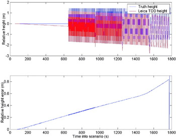
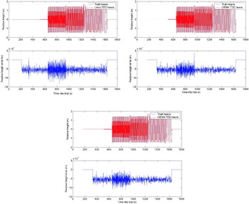
A strong correlation was seen between the truth height data and the relative height data produced through the integration of TDD velocities. Figure 3 shows the difference plot of the true height and integrated TDD velocity using Leica 530 dual frequency data; the bias of 98·470 m on the truth height was removed for this comparison. The results in Figure 3 clearly show the drift on the integrated TDD velocity caused by bias errors in velocity estimation. This drift was removed by passing the integrated TDD velocity through the high pass filter designed for the TDD heave algorithm. Figure 4 (Top left) shows a comparison between high pass filtered true height and high pass filtered integrated Leica 530 TDD velocity and it can be seen that the drift was removed by the filter; the results gained from data collected with the NovAtel OEM4 and U-Blox Antaris GPS receivers can be seen in Figure 4 (Top right ) and (Bottom) respectively.
Leica 530 integrated TDD position drift error from the marine scenario.

TDD heave error from the marine scenario for Leica 530 (Top left), NovAtel OEM4 (Top right) and U-Blox Antaris (Bottom).

A significant bias of 6 mm was evident in the heave error and can be seen in Figure 4. This was found to be caused by the finite stop band attenuation of the high pass filter used to produce truth heave data from truth height data. Truth height data, which had a bias of 98·470 m, was passed through the same high pass filter used to remove drift from the relative height data, produced through the integration of TDD vertical velocity. The stop band attenuation of the high pass filter was -80 dB and, whilst this level of attenuation is high, a residual bias was inevitable on the filtered height data. This is shown using the equation to calculate system gain in dB:
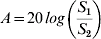
where A is the gain in dB and  represents the ratio of output and input. Setting the values of S 2=98·470 m and S 1=6 mm yields a gain of -84 dB, which is very close to the predicted stop band attenuation of the high pass filter.
The error plots in Figure 4 show that, when subjected to a dynamic scenario, the Leica and NovAtel receivers clearly outperformed the U-Blox receiver with errors which appeared over an order of magnitude smaller under visual inspection. It was also noted that the areas which contained the largest error on all the vertical velocity error plots coincided with the time when the receiver was subjected to the highest frequency of motion. Table 2 shows the errors in the TDD heave from each receiver when subjected to the various sea states during the trial.
The high level of performance of the NovAtel and Leica dual frequency receivers suggested that there was no catastrophic failure in the TDD heave algorithm causing the errors seen in the U-Blox TDD heave. It was therefore assumed that the large errors seen in the results of the U-Blox receiver were caused by the receiver itself and, more specifically, the receiver tracking loops. The results in Table 2 show that the errors in the TDD heave from the U-Blox receiver were much greater than those seen in the Leica and NovAtel receivers during sea state one yet they quickly reduced to levels of a similar magnitude when the frequency of motion was decreased during the remaining sea states. The TDD heave errors experienced by the U-Blox receiver during sea states three and four were no different to those seen when using the Leica and NovAtel. The peak and mean accelerations experienced by the vessel during the trial are presented in Table 3. Correlation of Table 3 with Table 2 gives an indication of what level of receiver induced error can be expected due to dynamic stress and suggests that degradation of performance of the U-Blox receiver began to be significant when accelerations of approximately 3 m/s2 were experienced.
Mean accelerations simulated during the marine trial.

It was clear from these results that the errors introduced by the U-Blox receiver when in motion were far larger than those introduced by either the Leica or the NovAtel. The largest errors occurred when the receiver was subjected to the highest frequencies of motion (in this trial a sinusoidal motion at 0·4 Hz saw the largest magnitude of error) and consequently when the signal tracking loops within the receiver are placed under the most dynamic stress. The extra dynamic stress on the carrier tracking loop was handled more easily in the receivers with higher grade components than in the U-Blox. It is believed that the relatively sluggish dynamic performance of the U-Blox receiver caused a significant lag in the output of the carrier tracking loop, and resulted in larger heave error. Also, it was thought that the increased receiver dynamics resulted in an increase in carrier tracking loop bandwidth in order to track the GPS signals, which had an adverse effect on carrier tracking loop noise. The true cause of the dynamic stress error at the firmware level is dificult to appreciate fully but it can certainly be surmised from the results obtained that higher accelerations, which place the receiver tracking loops under greater dynamic stress, cause errors in the U-Blox receiver that can be more than an order of magnitude greater than those seen in either of the dual frequency receivers.
7. PLYMOUTH SEA TRIAL
A sea trial of the developed low cost TDD heave algorithm was conducted in Plymouth on 2 August 2006 with the help of Sonardyne International Ltd., the industrial partner in the PhD project, who made their trial vessel, the Marco, available. The trial was intended to test the performance of the TDD heave algorithm as an alternative to inertial based heave algorithms by collecting raw GPS data from the same three receivers used in the simulator trials, processing it through the TDD heave algorithm and comparing the heave results to those obtained from both inertial based sensors and an Applanix POSRS fitted to the vessel. The following sensors and equipments were used:
• Applanix POSRS including Honeywell CIMU, Novatel OEM4 GPS receiver and a Novatel GPS 600 Pin-wheel antenna
• Two Leica 530 GPS receivers (numbered 1 and 2) and two Leica 504 choke ring antennas
• U-Blox Antaris AEK-4T GPS receiver and an ANN-MS-0005 patch antenna
• Honeywell HG1700 tactical grade IMU
• GPS reference station data supplied by Ordnance Survey
A TSS DMS500 MAHRS heave, pitch and roll sensor was also installed on the Marco but the data collected from this sensor were unusable due to time tagging errors. Once all the required sensors where fitted to Marco a trial was conducted that followed the general procedure of an approximately 20 minute initialization and alignment period for the POSRS followed by a period of simulated survey lines firstly within, then beyond, the Plymouth breakwater.
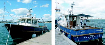
All sensors required were fitted to the Marco, (see Figure 5) the day before the trial. The IMUs were fitted below deck with the Honeywell CIMU placed on the lubber line and the Honeywell HG1700 just to starboard with a minimal lever arm. GPS antennas were fitted to the vessel in various positions dependent on availability of space. The Novatel Pinwheel antenna which formed part of the POSRS system was fitted to a mast, which was held rigid using two supporting struts, at the bow of the Marco. The Leica 504 choke ring antennas and the U-Blox ANN-MS-0-005 patch antenna were all fitted on a boom located on the starboard side of the Marco. The boom was held rigid with respect to the vessel with supporting struts and could be raised and lowered to aid antenna fitting.
The Marco.

Applanix POSRS data was processed within POSPac to produce a smoothed best estimate of trajectory (SBET), used as a reference trajectory against which other sensors were compared.
8. IMU DERIVED HEAVE RESULTS
The IMU derived heave data was processed using a heave algorithm designed at the IESSG based on a vertically damped INS. The IMU data was collected using a Honeywell HG1700 tactical grade IMU.
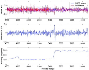
Table 4 shows a comparison between SBET heave and IMU derived heave in three key areas of the trial: figure-of-eight initialization turns, simulated survey lines within the breakwater and survey lines beyond the breakwater. The IMU derived heave results clearly demonstrated the instability of the feedback damping loop applied to the vertical channel of the HG1700 IMU. Vessel turns induced a large input into the heave filter and the transient performance of the feedback damping loop resulted in a ringing of the output. A period of time is required after a turn before the output from the feedback damping loop has settled once again. This phenomenon is well known and is seen in Figure 6 at approximately 5,500 s into the trial when the vessel turned at the end of a simulated survey line as shown with the comparison of heave error and heading data taken from the SBET trajectory.
Comparison of SBET heave and IMU derived heave during survey lines outside the breakwater.

IMU derived heave errors.

The standard deviation of the error for the figure-of-eight initialization turns and the survey lines conducted within the breakwater show a difference in accuracy. As expected, the standard deviation of the error when undergoing initialization was greater than that experienced during survey lines. This was due to the increased amount of turns during initialization, which induced errors in the IMU derived heave algorithm as previously explained.
The results for the survey lines conducted outside the breakwater showed an unexpectedly high standard deviation when compared to SBET heave. This was probably caused by the increased magnitude of heave once outside the breakwater, which went from a nominal height of ±0·2 m to a value of around ±0·5 m. This increase in heave magnitude was likely to have an adverse effect on IMU derived heave output due to the transient response of the feedback damping loop. The results of IMU derived heave outside the breakwater were a little disappointing but it should be remembered that the IMU heave algorithm developed for this paper is by no means complete and was only ever intended to demonstrate inertial heave characteristics and give an indication of the likely heave errors. It is expected that heave measurement using a commercially available inertial based heave sensor would have greater accuracy.
9. TDD HEAVE RESULTS
The TDD heave results were achieved using the same three GPS receivers used in the simulator trial. Raw data were collected on each receiver throughout the trial and processed using the TDD heave algorithm described above. All GPS data processed were subjected to an elevation mask of 15 degrees. Initial analysis was conducted using data collected at 1 Hz from each receiver and the results from this are shown in Tables 5, 6 and 7 for the Leica 530, Novatel OEM4 and U-Blox Antaris respectively.
Leica 530 TDD heave errors.

Novatel OEM4 TDD heave errors.

U-Blox Antaris TDD heave errors.

The mean error of 3 mm/s seen using each heave sensor was an artefact of the finite stop band attenuation on the high pass filter that was used to remove the ellipsoidal height bias from the SBET height to produce heave. The standard deviations of error in the heave signals were seen to be better in the Leica and NovAtel receivers compared to the U-Blox. This was expected due to the higher grade components used in those two receivers. The high quality results for the NovAtel receiver were probably due in some part to the decreased independence of the NovAtel GPS data as this data was also used to produce the reference trajectory by aiding the CIMU.
Overall, the results for each of the receivers were disappointing in terms of the standard deviation of error but they clearly demonstrated that the TDD heave algorithm was not subject to large excursions in heave during and after vessel turns. Further investigation pointed towards the data rate of the raw carrier phase observables as a source for the large standard deviations of errors seen. It was found that the 1 Hz data rate was insufficient to capture all the frequencies of motion within vessel heave and so heave data was under sampled. The only receiver that was used to collect GPS observables at a greater rate was the NovAtel OEM4, which collected data at 4 Hz.
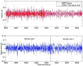
The 4 Hz NovAtel data was processed in the same way as the 1 Hz data and the results are presented in Table 8 and are demonstrated in Figure 7, which shows the NovAtel OEM4 4 Hz TDD accuracy during the survey lines beyond the breakwater. The results presented in Table 8 show a comparison between NovAtel OEM4 4 Hz TDD Heave and a reprocessed SBET solution that aids the CIMU with GPS data collected from the Leica 530 receiver. This allowed the NovAtel heave to be assessed against an independent reference. The results in Table 8 showed a marked improvement over the results for the same receiver recorded at 1 Hz and shown in Table 6. The increased data rate was more than adequate to cover all the frequencies of motion seen in the heave data so the 4 Hz heave was not subject to the aliasing which had occurred in the 1 Hz data. The NovAtel OEM4 4 Hz TDD heave results demonstrated the high quality of heave estimation possible using the TDD heave algorithm and it is expected that 4 Hz U-Blox data would show a similar improvement in accuracy over 1 Hz U-Blox data as seen with the NovAtel.
NovAtel OEM4 TDD 4Hz heave error during survey lines conducted beyond the breakwater.

NovAtel OEM4 4 Hz TDD heave errors.

10. SUMMARY AND CONCLUSIONS
A highly accurate heave estimation algorithm, termed temporal double difference (TDD) heave, that uses stand-alone low cost GPS receivers was developed. This used carrier phase observations from adjacent epochs, differenced to produce user velocity, the vertical channel of which was then integrated to produce relative vertical position. A high pass filter was also designed and used to remove any drift on the relative position output that may exist due to bias errors on the vertical velocity estimation, resulting in highly accurate heave estimation.
The Spirent simulator trial conducted as part of the research contained within this paper has been the first to explore the quality of the recorded carrier phase observable measured with commercially available low cost GPS receivers when compared to the measurements taken from dual frequency receivers. By using three separate receivers of varying grades to record simulated data from the same scenarios, receiver based errors were isolated and quantified. This was extended to cover data from two distinct sets of dynamics that were able to test the performance of the receiver signal tracking loops under dynamic stress.
Under static conditions the TDD velocity estimation using the U-Blox receiver was of a comparable quality to those seen when using the Novatel and Leica receivers. This is thought to be caused by the limitation of the bandwidth of the signal tracking loop within the U-Blox receiver based on the knowledge that the receiver is stationary. The use of this extra information enables the U-Blox receiver to level the playing field somewhat, allowing the signal tracking loops within the receiver to record accurate measurements of the carrier phase observable with reduced tracking loop bandwidth whilst acting well within their dynamic stress limitations.
When under dynamic conditions, of the order of those which may be expected in a marine environment, a divergence in the performance of the three receivers was found to exist. The quality of the measurements recorded with the U-Blox receiver was now significantly reduced when compared to those recorded using either the Novatel or the Leica. As such the TDD heave estimates produced using the data from the U-Blox receiver were also less accurate than those produced from data recorded using the Leica or Novatel receivers. Errors in TDD heave from the U-Blox receiver were approximately an order of magnitude greater than those seen from the other receivers at the highest frequencies of motion.
The sea trial was conducted in order to test the TDD heave algorithm calculated using data recorded with the three receivers previously used in the simulator trial against an IMU derived heave estimate and highly accurate Applanix POSRS reference data. The magnitude of the IMU derived heave error was considered to be too great, which was likely due to the quality of the algorithm in use. The heave algorithm developed during the project was simply a damped INS vertical channel and employed none of the velocity aiding algorithms that commercial heave sensors use. The IMU derived heave results did demonstrate the stability and usability issues implicit with the use of inertial heave sensors, however.
The results of TDD heave demonstrated clearly the benefits available to the TDD heave user compared to the inertial based heave user. Each receiver's TDD heave output demonstrated increased stability over IMU derived heave and no tuning was required by the user as is required with inertial heave sensors. The magnitude of the errors seen in the TDD heave solution using all three receivers were larger than was expected due to the under sampling of vessel heave motion at 1 Hz. Even with the aliasing that occurred due to that under sampling, the results do show the ability of U-Blox TDD heave to compete with heave produced from other GPS receivers in terms of accuracy.
The TDD heave results for the sea trial were all based on GPS data recorded at 1 Hz. Through analysis this data rate was found to be inadequate for the measurement of the frequency of heave motion experienced by the vessel during the trial. A 4 Hz TDD heave solution was processed using data collected from the Novatel OEM4 receiver, the only receiver used in the trial to log raw observables at a higher data rate. The Novatel 4 Hz TDD heave was compared to an SBET solution that was processed in POSPac using the 1 Hz Leica 530 collected during the trial; this was done so as to provide independent reference data as the previous SBET solution was processed using the Novatel OEM4 data. The Novatel 4 Hz TDD heave showed a vastly increased level of performance over the heave solutions using 1 Hz data and exhibited no adverse effects due to higher frequency heave motion.
Overall, the results of the sea trial show the ability of TDD heave to measure heave to the accuracy required for at least IHO survey order one and possibly IHO special order when using high grade GPS receivers such as the Novatel OEM4. It is expected that U-Blox TDD heave would see a marked improvement in accuracy over the figures seen in Table 7 if data were collected at a higher rate, say 4 Hz. The TDD heave outputs exhibited no errors due to the temporal instability that is experienced in the use of inertial based heave sensors and also required no inputs from the user. These factors show the ability of TDD heave using commercially available low cost GPS receivers to compete with inertial based sensors in terms of accuracy, and generate savings to the survey industry. These savings come in the form of reduced unit cost, reduced lead in time to survey lines and reduced user burden.