

Introduction
The goal of NASA's forward contamination planetary protection policy is the protection of celestial bodies and scientific investigations (Rummel & Billings Reference Rummel and Billings2004); it specifically states that ‘the conduct of scientific investigations of possible extraterrestrial life forms, precursors, and remnants must not be jeopardized’ (NASA 1999). This has been the approach taken by the Committee on Space Research (COSPAR), for the past four decades. Consistent with this approach, the protection of the ability to perform scientific measurements without confounding them with false positives has been the focus of past National Research Council (NRC) examinations of forward contamination planetary protection policy for Mars. In its 1992 report, Biological Contamination of Mars: Issues and Recommendations, the Space Studies Board (SSB) Task Group on Planetary Protection emphasized that ‘the philosophical intent of the 1978 committee (the SSB committee that had previously addressed the topic) to protect Mars from terrestrial contamination so as not to jeopardize future life-detection experiments on Mars is still profoundly important’ (NRC 1992, p. 57). To this end, the purpose of this study was to determine the potential for microbial contaminants on a Mars lander, such as Phoenix, to be dispersed to the Martian surface during landing.
Soft-landing planetary spacecraft utilize descent engines to lower them to the surface. This results in the impingement of engine plumes on the regolith for a few seconds during touchdown – less than 2 seconds for Phoenix. Potentially, the effect is to vigorously erode the immediate surface and as Fig. 1 shows, the typical engine arrangement of landers leads to ‘captured’ reverse flow of plume gases back to the underside of the spacecraft as the plumes react against the regolith. Modelling predicts that this particle-laden reverse flow will lead to scouring of the spacecraft underside and consequent transfer of any microbial contaminants to a planetary surface.
Typical lander engine arrangement with several thrusters positioned on platform perimeter. This leads to captured reverse flow eddies impinging on the spacecraft underside (highly simplified).

Phoenix was the first NASA mission to use pulsed engines operating by rapid firing at a frequency of 10 Hz as a means of precisely controlling thrust. All previous lunar and Mars missions used steady-state engines. Pulsed engines cause soil erosion not only by viscous drag and macroscopic shear of soil clumps (like steady-state engines) but also by explosive soil reaction of the fluidized soil when the engines shut down (Scott & Ko Reference Scott and Ko1968; Metzger et al. Reference Metzger, Immer, Donahue, Vue, Latta and Deyo-Svendsen2009). Mehta et al. (Reference Mehta, Renno, Marshall, Grover, Sengupta, Rusche, Kok, Arvidson, Markiewicz, Lemmon and Smith2010) believe that pulsed engines additionally create cyclic shock waves that dramatically increase soil erosion over steady-state engines.
The Phoenix mission had concerns that the descent thrusters might cause soil erosion that would affect spacecraft landing stability, destruction of soil structure in the spacecraft vicinity and general contamination of the lander by thruster-induced sandblasting erosion and soil deposition on lander structures. A study was therefore initiated to test this experimentally with a half-scale lander model; results are described by Mehta et al. (Reference Mehta, Renno, Marshall, Grover, Sengupta, Rusche, Kok, Arvidson, Markiewicz, Lemmon and Smith2010). The study was led by M. Mehta and N. Renno of the University of Michigan (UM), and coordinated with Phoenix by the first author. The UM effort was supported by CFD (Computational Fluid Dynamics) modelling input from the Phoenix EDL (Entry, Descent, Landing) team at Lockheed Martin. Experiments were conducted at NASA Ames using the PAL (Planetary Aeolian Laboratory, operated by Arizona State University), which enabled tests to be run at Martian pressures of ∼7 mbar.
A complementary study reported here ‘piggybacked’ planetary protection experiments on the PAL tests by attaching microbially populated witness plates on the underside of the lander model. These experiments were intended to serve the interests not only of Phoenix, but also other planetary missions using soft landers. Details of the test rig, thruster design, scaling issues and other technical data are described in Mehta et al. (Reference Mehta, Renno, Marshall, Grover, Sengupta, Rusche, Kok, Arvidson, Markiewicz, Lemmon and Smith2010).
Experimental set-up
In order to determine whether particle-laden plumes from landing thrusters actually erode spores from lander surfaces, we placed a triangular plate mounted with sets of ‘contaminated’ witness coupons on the underside of the lander model as seen in Fig. 2. This image shows the triangular plate wedged into the 60-degree test rig operating angle (the 60 degrees represents a discrete segment of gas flow, with the walls being equivalent to the stagnation boundaries between thruster-induced eddies). The thrusters are pointing downward into the test bed. Note that the twin-thruster exhaust orifices are asymmetrically positioned with respect to the plate. Also shown in Fig. 2 are the positions of five coupon sets; each set had three coupon positions. The individual coupons were aluminium tablets 9×23×1 mm affixed to the mounting plate by double-sided sticky tape. In order to prevent the coupons locally affecting gas flow around them, they were recessed with their upper surface flush with the plate top surface. Coupons in position 1 had microbial spores on their surfaces, those in position 2 had fluorescent microbeads as an inorganic control and those in position 3 had an aluminium foil cover to record particle impacts.
Mounting plate for PP coupons. Top: As mounted on the Phoenix rest rig (looking upwards) after test 3 –note adhering dust. Bottom: Position of coupon sets and numbering code –vertical apex inserted towards the centre of the test rig. The triangular plate is 27 cm on a side (only 3 of the 5 positions were used).

The thrusters used high-pressure nitrogen rather than the rocket fuel hydrazine used by Phoenix. The thrusters were designed to reproduce the supersonic plume exhaust velocity and plume configuration generated by the full-scale lander.
Preparation of coupons
Bacillus subtilis HA101 was grown in spore medium containing the following additions (in grams), in a final volume of 200 ml: Nutrient Broth (Difco), 3.2; KCl (Sigma), 1.0. The following sterile nutrient solutions were added to the cool medium: CaCl2 1 M, 0.4 ml; FeCl3 0.01 M, 0.2 ml; MnSO4 0.01 M, 0.4 ml; MgSO4 0.10 M, 0.2 ml; glucose (50%), 0.4 ml. The culture was incubated at 37°C in a shaker for 4 days. The cells/spores were pelleted by centrifugation at 5000 g for 15 minutes.
The pellet was subsequently resuspended in 30 ml 0.01 M Tris buffer of pH 7. Then the following solutions were added: DNase 2 μg/ml final concentration, 0.3 ml; Lysozyme 200 μg/ml final concentration, 0.3 ml; MgSO4 0.01 M, 2.5 μl/ml final concentration, 30 μl. The resuspended pellet was incubated at 37°C for 30 minutes and at 80°C in an incubator shaker at 150 rpm, for 10 minutes. This step was followed by centrifugation at 5000 g for 15 minutes, before the pellet was resuspended in 50 ml DI water and washed three times. The final pellet (about 1010 spores/μl) was resuspended in 10 ml sterile DI water and stored at 4°C. Just prior to use the spore pellet was resuspended in the appropriate amount of filter sterilized 0.8% aqueous sodium chloride to achieve 2.84×10⁷ spores/μl.
The fluorescent microspheres of 6 μm diameter were obtained from the InSpeck Green (505/515) Microscope Image Intensity Calibration Kit (Molecular Probes Catalog no. I-14785). The ‘Component G’ from the Kit was concentrated via centrifugation to achieve an estimated 107 microspheres/μl.
The spore and bead suspensions were placed in 10 μl aliquots onto the aluminium coupons and allowed to air dry. The dried suspension covered an area approximately 1 cm2. After drying, the coupons were then affixed to the triangular test plate. The amount and concentration of spores and beads were the same for all experiments.
For detecting particle impacts, standard thickness aluminium foil was attached to coupons in position 3 using double-sided sticky tape. The foil is easily indented by particle impact, especially with the compliant sticky tape as a substrate. Impact intensity can then be determined under the microscope. Impact sites can, in principle, record particle velocity, particle flux and impact angle, although velocity can only be determined by calibration (not conducted for these tests).
Test conditions
All tests were conducted at room temperature, but at Mars atmospheric pressure of 7 mbar with the test rig inside the PAL facility. Owing to a series of system failures in the steam plant that generates the vacuum for PAL, we were only able to conduct three experiments with available resources. Each experiment involved preparation and delivery of the test plate to PAL on the day prior to a test, and retrieval of the plate 24 hours later. PAL itself is a 4644 m3 vacuum chamber with a 33 m high ceiling. This has to be pumped down to Mars pressure over about 90 minutes and repressurized over about 30 minutes. Table 1 shows the test matrix. From this matrix we were able to compare pulsed engines with steady-state ones, and the difference between sand and silt size test beds.
Test matrix for PP experiments

The bed material was composed of crushed walnut shell (a common industrial abrasive cleaning material frequently used in Mars Aeolian simulations) that has shape properties similar to natural elastic silicate particulates, and a density ∼1 g/cm3. The density is three times less than basalt, and the gravity on Mars is three times less than on Earth, and so the material weight had appropriate similitude.
Results
Reaction of the bed
High-speed filming showed that the thrusters created extremely violent clouds and ejecta of particulate material as the test bed became cratered by the engine plumes (images of the bed reaction can be seen in Mehta et al. Reference Mehta, Renno, Marshall, Grover, Sengupta, Rusche, Kok, Arvidson, Markiewicz, Lemmon and Smith2010). As expected, the pulsed engine mode was more aggressive than the steady-state mode with regard to bed erosion. The engine plumes created soil craters of less than a meter in radius. The depth of excavation would have been much greater if the solid basement beneath the soil (walnut shell) had been deeper than 20 cm. But particles excavated from the craters were blown 10–15 m in every direction, completely covering the whole lab floor and all equipment in the PAL facility to a uniform depth of ∼1 mm. The lateral extent of dispersion was only terminated by the chamber walls. Minor fluidized soil deposition of 1–2 cm occurred around the crater, rather than a blanket that was very thick near the crater with radial thinning, as might have been expected. Phoenix produced a similar pattern of deposition (Fig. 3; Smith et al. Reference Smith2009). This indicates that the bed was dispersed ballistically rather than by gas transport, and particles must therefore have attained extremely high velocities. This is consistent with impact pitting on the aluminium foil coupons (Fig. 4).
Robot Arm Camera image of cratering under the Phoenix lander. Soil has been completely stripped down to the ice table. The right side of the image shows piling up of soil under the centre of the lander where the plume eddies converge.

Aluminium foil impact-registering coupons. Each pit in the foil represents a particle impact. Numbering corresponds to the three tests and the five coupon positions as shown in Fig. 2. All images have the same magnification. Each frame is 1800 μm across. All images were acquired with high-angle (85°) illumination angle from top left.

Bearing in mind that the test rig was a half-scale model, the results are very close to those observed by Phoenix itself. Images from MRO (Mars Reconnaissance Orbiter) showed a soil dispersion radius of ∼20 m (Smith et al. Reference Smith2009). Figure 3 shows an image taken by the Robotic Arm Camera on Phoenix underneath the lander, indicating that 5–20 cm of soil had been completely stripped from the water ice basement (Sizemore et al. Reference Sizemore, Mellon, Searls, Lemmon, Zent, Heet, Arvidson, Blaney and Keller2010). This confirmed to a large extent that the PAL Phoenix model provided an accurate assessment of soil erosion potential. Commensurately, it must be assumed that the sandblasting effect observed on the model is also a realistic simulation of effects on the lander. The craters seen in Fig. 3 are also close to the same size as those produced by the test rig. The presence of the ice table at shallow depth fortuitously allowed even closer comparison of the test rig results with the actual lander experience – the test rig craters also bottomed out on a hard surface at the same depth.
Spore and bead erosion
The energetic particle-laden eddies caused erosion of the spore and bead ‘contaminants’ as expected (Fig. 5), but with an unexpected efficiency. Test 3 (Table 1) with very fine soil particles led to adhesion of material to the coupons that prevented any meaningful analysis of spore and bead residual populations. However, the coupons for tests 1 and 2 yielded very clear statistical data.
Photomicrograph of spores and beads on coupons before and after test. (a) Bacillus subtilis spores on control coupon. (b) Coupon after test. (c) 6 μm microspheres on control coupon. (d) Bead coupon after test. Width of image fields =100 μm.

The residual spore and bead populations were viewed at 3000× with a Keyence VH-6300 high-resolution digital microscope equipped with a VH-Z450 high-range zoom lens. The coupons were sub-divided into 50 fields of view in which the spores and beads were counted. Each field of view was 145 μm2, with a total of 7250 μm2 viewed for each coupon. Results of the counts are given in Table 2. Additionally, the intensity of the fluorescence of the coupons containing the fluorescent beads was analysed on a Typhoon Trio Variable Mode Imager. Test and control coupons containing fluorescent beads were placed on the Typhoon simultaneously and the intensity of the fluorescence emanating from each coupon was measured and compared to a control intensity value (Table 3).
Average and standard deviation of spore and bead counts on coupons after testing. Non-applicable (N/A) cases occur when the coupon was covered with dust

Proportion of beads on coupons from tests 1 and 2 based on relative UV3 fluorescence intensity, normalized to 1000 intensity units for the control coupon
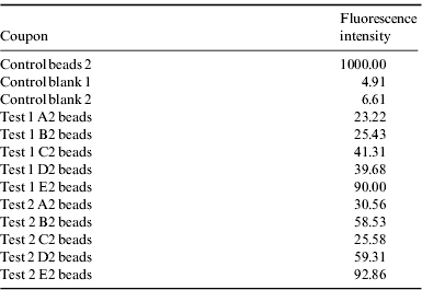
The results in Table 2 indicate that only a small fraction (8.8% and 4.1%, respectively) of the spores remained on the coupons in tests 1 and 2, whereas none (0%) of the beads were left on the coupons after the tests as far as could be determined from the microscopic counts. However, fluorescence data indicated about 3% residual population of the beads.
Figure 4 illustrates the effect of particle-laden plume eddies on the aluminium foil coupons, recalling that tests 1 and 2 were conducted with sand-size particles while test 3 had silt-size particles that adhered to the coupons. Strong pitting from particle impact is evident in tests 1 and 2 with coupon positions B and D most affected. In test 3, the silt particles coated the coupons and it is evident from Fig. 4 that the foil was unscathed, although this does not necessarily imply that particle impacts were unable to erode surface contaminants (adhering dust was washed off for microscope examination). Test 3 images are identical to reference surfaces of aluminium foil. There is no obvious coupon−position correlation between data tabulated in Table 2 and images in Fig. 4 in terms of impingement energy implied by residual contaminant populations or crater sizes.
Discussion and conclusions
Experiments clearly illustrate that spacecraft contaminants such as spores can be scoured by descent engine plume eddies, regardless of whether the engines are pulsed or steady state. Observations of soil cratering and dispersion by the Phoenix lander confirm the efficacy of the Ames PAL simulations, and by implication, validate the planetary protection findings. Results indicate that planetary protection protocols need to consider spacecraft cleanliness in terms of surfaces exposed to soil movement, rather than just designated soil-processing functions of spacecraft components such as digging, funnelling, etc.
Planetary protection experiments were conducted on a Phoenix lander simulation platform but nevertheless provided a more general assessment of contaminant (spore) scouring for a variety of missions. Viking landers used canted engines and more dispersed plumes to counteract soil erosion, but even this did not prevent a soil clod from being thrown onto one of the lander masts (B. Clark, personal communication, 2007). It is reasonable to assume that soil scouring beneath the Viking lander also occurred. Phoenix was a revived HEDS lander and did not have any design aspects to reduce soil erosion. In fact, the use of pulsed engines exacerbated the problem.
The current approach to planetary protection for missions like Phoenix is to adopt two levels of spacecraft cleanliness – a relatively low level for parts that will not (intentionally) touch the soil, and a relatively high level for soil scoops and other parts that are intended for soil contact. The basis for this approach is the assumption that the soil/spacecraft contacts are only going to be the ones planned for. In reality, the soil comes into contact with just about every external surface on the spacecraft as a result of soil aeroturbation by the engine plumes, and this soil contains contaminants scoured from the lander's underside, along with solid, liquid and gaseous contaminants from the engines themselves. The Phoenix microscope actually employed this phenomenon (successfully) to collect dust for the microscope during landing. If contaminants move from a spacecraft into the soil, and then a robotic arm or rover comes in contact with this soil, the extra cleanliness of the arm or rover is invalidated. Essentially, descent engine plumes become ‘equalizers’ that reduce soil, spacecraft and special spacecraft hardware more or less to the same effective level of contamination.
Acknowledgements
Funding for this study was provided by the Mars Program Office at JPL and in part from the Phoenix mission through the University of Arizona. Technical support was provided by R. Landheim (formerly) of the SETI Institute, N. Renno and M. Mehta at the University of Michigan, and R. Greeley and C. Woosley (formerly) of Arizona State University.



