Introduction
Heterogeneous catalysis is a key process for converting reactants into products, and it plays a critical role in chemical and energy transformations.Reference Ertl, Knözinger and Weitkamp1,Reference Somorjai and Li2 An industrial heterogeneous catalyst typically consists of nanostructured particles of variable shape and composition. The surfaces of catalytic particles interact with gas- or liquid-phase reactants and promote product generation. Reactions typically take place at temperatures up to 1000°C. As the catalytic materials convert gas- or liquid-phase reactants into products, the ambient gas or liquid environment also changes the surface and even the bulk form of the nanoparticles. During catalysis, the structure of the catalyst can vary in complex ways with changes in the pressures of the reactants and products as well as in the temperature. To build a structure–reactivity–performance correlation and achieve a fundamental understanding of catalytic mechanisms, the electronic and geometric structure of the catalyst must be determined at the atomic level. Environmental transmission electron microscopy (ETEM) is the only high-spatial-resolution technique available to perform in situ characterization of high-surface-area catalysts. In this approach, reactants are allowed to flow over the TEM sample (often during in situ heating), and the changes in the nanocatalyst particles are recorded using TEM imaging, diffraction, or spectroscopy techniques.
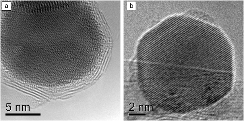
Catalysts are dynamic entities that change not only during each reaction cycle, but also on a longer time scale through phase transformations, surface restructuring, and particle growth. An example of this is illustrated in Figure 1, which shows a supported Ru catalyst for ammonia synthesis. In a vacuum, each Ru particle is encapsulated in a shell of BN, but under a reactive environment, this shell is no longer present.Reference Hansen, Wagner, Hansen, Dahl, Topsoe and Jacobson3
Boron nitride (BN) supported ruthenium particles.Reference Hansen, Wagner, Hansen, Dahl, Topsoe and Jacobson3 (a) In a vacuum, the BN support creates shells encapsulating the metal particles. (b) When exposed to a reactive environment of N2 and H2 at 552°C, the shells are removed. Reproduced with permission from Reference 3. © 2001 American Association for the Advancement of Science.

To build a direct correlation between catalyst structure and catalytic performance, structural information at the atomic or nanoscale level obtained under reaction conditions is critical. The value of the ETEM approach for characterizing high-surface-area materials was recognized by early workers in the field. Baker and co-workers were the first to extensively apply the technique to heterogeneous catalysts in a series of early works, elucidating the nanoscale mechanisms for carbon formation and catalyst sintering.Reference Baker, Barber, Harris, Feates and White4,Reference Baker, Harris, Thomas and Waite5 In the current article, we limit ourselves to select examples drawn mostly from the past 10 years focusing on gas-phase reactions/products. For reviews of earlier work, see References 6–9.
Atomic-resolution environmental in situ microscopy
A critical technical requirement for all gas systems compatible with TEM is that they maintain both a high gas pressure around a sample and a high vacuum throughout most of the column and the electron source. Two common approaches are currently employed to satisfy this requirement: the window method and differential pumping.
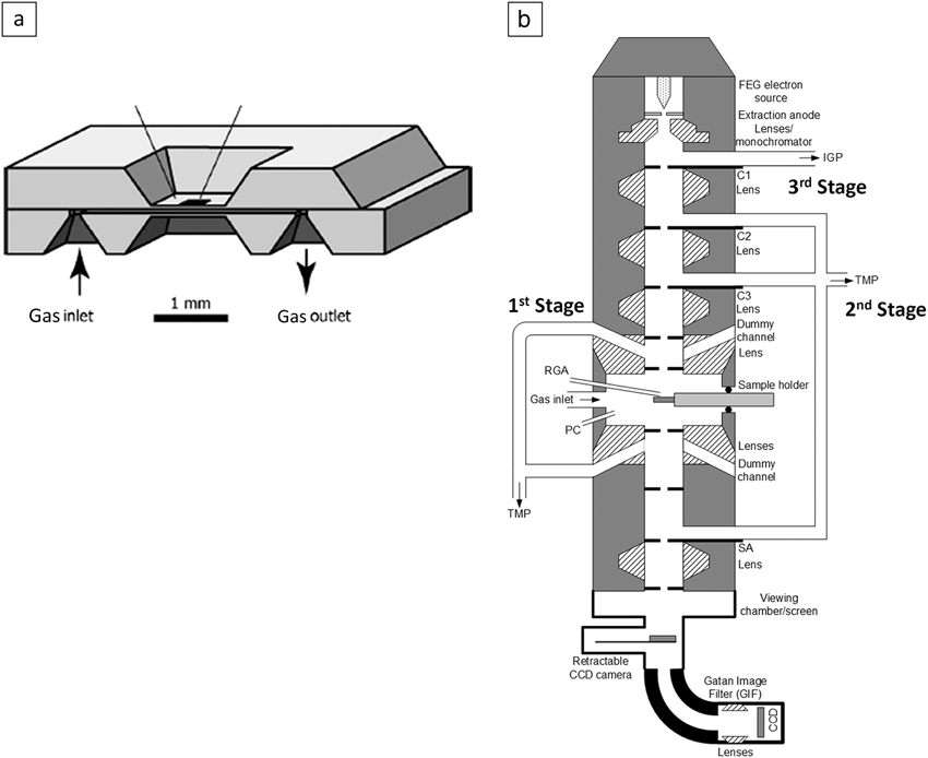
In the window method, thin electron-transparent membranes (e.g., Si3N4 or graphene films) are employed to separate the high-pressure atmosphere around the sample from the high vacuum in the rest of the microscope. This is usually accomplished by means of a sample holder that incorporates windows along with a gas inlet and outlet system. Atomic resolution has been demonstrated with such a system.Reference Giorgio, Sao Joao, Nitsche, Chaudanson, Sitja and Henry10,Reference Parkinson11 Recent application of microelectromechanical systems (MEMS) technology has resulted in the development of structures in which the area of the thin window is rather small, typically ∼50 μm across, permitting higher pressure to be maintained (Figure 2a). A group at the Technical University of Delft first demonstrated an atomic resolution of 0.18 nm at pressures above 1 atm (∼105 Pa ∼1 Bar) and temperatures up to 500°C.Reference Creemer, Helveg, Hoveling, Ullmann, Molenbroek, Sarro and Zandbergen12 Prior to the development of MEMS windows, differentially pumped systems typically reached only between 10 and 20 mbar. Recent results showed that controlled-atmosphere experiments with windowed cells can be performed at pressures up to 4 atm (∼4 bar) and elevated temperatures.Reference Alan, Yokosawa, Gaspar, Pandraud, Paul, Creemer, Sarro and Zandbergen13,Reference Yokosawa, Alan, Pandraud, Dam and Zandbergen14 The issue of temperature measurement when a gas of variable pressure and composition is introduced is an ongoing challenge in MEMS-based windowed cells. Approaches are being developed that exploit changes in membrane conductivity and changes in the gas density to address this issue.Reference Vendelbo, Kooyman, Creemer, Morana, Mele, Dona, Nelissen and Helveg15
(a) Schematic diagram of a microelectromechanical systems-based windowed cell reactor.Reference Creemer, Helveg, Hoveling, Ullmann, Molenbroek, Sarro and Zandbergen12 (b) Schematic diagram of a differentially pumped environmental transmission electron microscopy apparatus.16 Note: CCD, charge-coupled device; FEG, field-emission gun; IGP, ion getter pump; PC, plasma cleaner; RGA, residual gas analyzer; SA, selected-area aperture; TMP, turbomolecular pump.
The second approach to creating a reactive gas atmosphere is to employ a differentially pumped system; historical reviews of this approach can be found elsewhere.Reference Sharma, Crozier, Yao and Wang9,Reference Hansen, Wagner and Dunin-Borkowski16 Modern differential pumping systems are designed following the basic principles outlined by Swann and Tighe.Reference Swann and Tighe17 In this type of cell, the large pressure difference between the sample area and the microscope column is maintained by inserting a series of differential pumping apertures and adding additional pumping capacity. Atomic resolution was first achieved by a group at the University of Oxford on a modified JEOL 4000 instrument,Reference Doole, Parkinson and Stead18 and the approach was continuously developed throughout the 1990s, often by means of substantial modification of the objective-lens pole pieces, as pioneered by Boyes and Gai.Reference Lee, Dewald, Eades, Robertson and Birnbaum19–Reference Sharma and Weiss21 Differential pumping systems compatible with field-emission electron sources were demonstrated,Reference Hansen and Wagner22 and modern systems with aberration correction are currently available.Reference Hansen, Wagner and Dunin-Borkowski16,Reference Jinschek and Helveg23
A schematic diagram of a differentially pumped system is shown in Figure 2b. The microscope column (FEI Titan) has been modified to add three sets of differential pumping apertures for three pumping stages between the gun valve and viewing chamber. The first two sets of apertures are placed within the upper and lower objective-lens pole pieces, and most of the gas leaking through this first set of apertures is pumped out using a turbomolecular pump. The second stage is between the condenser aperture and selected-area aperture and is pumped using a second turbomolecular pump. An additional ion pump is employed for the last stage before the gun valve.
Atomic-scale structural changes during gas exposure
Catalyst preparation
Catalyst preparation often involves oxidation and reduction treatments of metal precursors to generate dispersions of metallic nanoparticles on high-surface-area supports such as Al2O3, SiO2, and TiO2. ETEM has also been employed to follow the evolution of metal-supported catalysts during calcination and reduction. One advantage of the ETEM approach is that it allows the spatial distributions of the metal precursor, intermediate oxide, and final metal to be correlated from the same region of the catalytic material. Li et al. followed the evolution of a variety of metallic systems (Ni, NiCu, Co, and CoRu) prepared using impregnation techniques and high-surface-area supports.Reference Li, Liu, Nag and Crozier24 The ability to perform in situ high-spatial-resolution electron energy-loss spectroscopy (EELS) in STEM mode is very beneficial in the study of bimetallic systems, where compositional heterogeneity might not be apparent from the TEM or STEM images.
For example, compositionally distinct domains in a 5-nm NiCu particle were observed in H2 at 300°C, demonstrating the promotional effect of Cu in reducing NiO to Ni metal in bimetallic particles.Reference Li, Liu, Nag and Crozier24 Banerjee and Crozier also undertook an investigation of the preparation of model Ni catalysts supported on SiO2 spheres during both the calcination and reduction steps.Reference Banerjee and Crozier25 The simple geometry of this support made it easier to see metal diffusion during reduction and demonstrated that, for this system, finer metal dispersions were obtained by eliminating the calcination step and performing a direct reduction in H2.
Dehghan et al. investigated the reducibility of cobalt oxide on 12 wt% Co/α-Al2O3 with and without a 0.5 wt% Re promoter.Reference Dehghan, Hansen, Wagner, Holmen, Rytter, Borg and Walmsley26 Using imaging and EELS, they were able to show that, in 3 mbar of H2, the initial Co3O4 started to transform to CoO at 180°C, and Co metal started to appear at 260°C, with complete reduction at 360°C. A similar result was also found for a CoOx/SiO2 composite system, which also exhibited nucleation and growth of metal particles during reduction.Reference Xin, Pach, Diaz, Stach, Salmeron and Zheng27
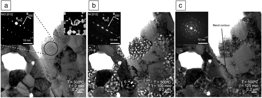
Catalyst activation can be thought of as a process taking place inside a reactor that leads to the formation of catalytically active species with the desired activity and selectivity. For example, the as-prepared anode on a solid-oxide fuel cell is often composed of a composite consisting of NiO and yttria-stabilized zirconia (YSZ). The fuel cell anode must be activated by reducing the NiO to Ni metal, which then acts as both a current collector and a catalyst. ETEM has been employed to follow the evolution of the anode under both reducing and oxidizing conditions.Reference Jeangros, Faes, Wagner, Hansen, Aschauer, Van Herle, Hessler-Wyser and Dunin-Borkowski28Figure 3 shows the evolution of the anode during a reduction and oxidation cycle. The initially dense NiO grains convert to a porous Ni metal structure during reduction (due to the volume shrinkage associated with the oxide-to-metal phase transformation). Interestingly, during reoxidation, NiO forms void-like structures, leading to an overall expansion in the NiO phase compared to the original NiO, which results in strain in the adjacent YSZ grains, as seen in Figure 3, and eventually leads to anode failure.
In situ reduction and reoxidation of a Ni/yttria-stabilized zirconia (YSZ) fuel-cell anode:Reference Jeangros, Faes, Wagner, Hansen, Aschauer, Van Herle, Hessler-Wyser and Dunin-Borkowski28 (a) initial structure composed of NiO/YSZ, (b) fully reduced anode showing porous Ni metal regions, and (c) reoxidized anode showing formation of porous NiO regions and a bend contour in YSZ, indicative of strain. Insets are electron diffraction patterns and an Ni elemental map. Reproduced with permission from Reference 28. © 2010 Elsevier Limited.
Structural evolution under reaction conditions
This broad category focuses on performing in situ imaging, spectroscopy, and diffraction on metal and oxide catalysts under near-reaction conditions. Some of the examples discussed next illustrate how the catalytic structure can change upon exposure to reactive gases and how structure can be correlated with reactivity.
Gold for CO oxidation
Au nanoparticles have received considerable attention because of their high activity for CO oxidation.Reference Haruta, Yamada, Kobayashi and Iijima29 Giorgio and co-workers conducted several studies on the shape of Au nanoparticles on MgO, TiO2, and carbon supports in 1 mbar of O2, H2, and CO + O2 at room temperature.Reference Giorgio, Sao Joao, Nitsche, Chaudanson, Sitja and Henry10,Reference Giorgio, Cabie and Henry30 Exposure to H2 resulted in the particles assuming truncated octahedral shapes bounded by (111) and (100) facets, whereas exposure to O2 resulted in the particles assuming a more rounded shape. This behavior was interpreted to indicate that O2 chemisorbs at edges and defect sites. They repeated these experiments for CO oxidation and found that the Au particles were also predominantly round when CO2 was produced.
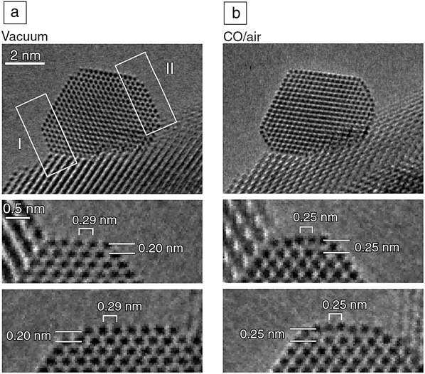
Takeda’s group has investigated the structure of Au particles on CeO2 at room temperature in the presence of CO and O2.Reference Uchiyama, Yoshida, Kuwauchi, Ichikawa, Shimada, Haruta and Takeda31 They also found that truncated octahedra formed when CO was present, and more rounded shapes formed in the presence of only oxygen (or air). Interestingly, even very low concentrations of CO mixed with oxygen stabilized the (111) and (100) facets on Au, presumably because of the much larger chemisorption energy of CO compared to O2. Under CO oxidation conditions, predominantly faceted particles with slightly rounded corners were observed. The same group recently repeated some of this work using aberration-corrected ETEM in 1 vol% CO in air (0.5 mbar) at room temperature.Reference Yoshida, Kuwauchi, Jinschek, Sun, Tanaka, Kohyama, Shimada, Haruta and Takeda32 They observed an outward relaxation of about 0.5 Å of the top (100) layer in the presence of CO (see Figure 4). When ETEM was performed at 80 kV, the sensitivity to light atoms was increased. Contrast on the surface of the Au nanoparticles was observed that appeared to be consistent with direct imaging of CO adsorbates. This might open up the exciting possibility of directly imaging gas adsorbates on the surfaces of nanoparticles.
Gold nanoparticles supported on cerium oxide in (a) a vacuum and (b) a mixture of CO and air.Reference Yoshida, Kuwauchi, Jinschek, Sun, Tanaka, Kohyama, Shimada, Haruta and Takeda32 The middle and bottom rows show magnified images of the facets labeled I and II, respectively. When exposed to the CO gas mixture, the top-most Au layer on the {100} facets (indicated by white rectangles, top row) expands by 0.05 nm (middle and bottom rows). Reproduced with permission from Reference 32. © 2012 American Association for the Advancement of Science.
Structure–reactivity relations from ETEM
Phase changes in Ni catalysts have also been correlated directly with catalytic activity for hydrocarbon reforming. Chenna and co-workersReference Chenna, Banerjee and Crozier33,Reference Chenna and Crozier34 used ETEM to determine the phase changes taking place on Ni/SiO2 catalysts during temperature ramping and correlated these structural changes with changes in activity and selectivity determined by ex situ reactor studies. During ramping in 1.5 mbar of 2CH4 + O2, at 400°C, the initial metallic Ni particles convert to NiO particles showing Kirkendall voids (see Figure 5). The NiO catalyzes complete oxidation of CH4, resulting in the production of CO2 and H2O. As the temperature continues to rise, all of the oxygen in the reactor is converted, and the atmosphere becomes reducing, such that the NiO is reduced back to Ni metal at about 700°C. At this point, reforming begins, and the products change from CO2 and H2O to CO and H2. The major changes in catalyst selectivity that appear at 400°C and 700°C correlate precisely with structural transformations determined by ETEM. The structure–reactivity relation derived from ETEM is shown schematically in the inset of Figure 5b.
In situ environmental transmission electron microscope images and electron diffraction patterns of Ni/SiO2: (a) in the presence of 1.5 mbar of H2 at 400°C and (b) from the same region in the presence of 1.5 mbar of a mixture of CH4 and O2 in a 2:1 ratio at 400°C. (c) Structure–reactivity relations showing schematic diagrams of catalyst structure superimposed on catalytic data. The catalytic data show O2 and CH4 conversion along with selectivities for CO and CO2.33 Reproduced with permission from Reference 33. © 2011 Wiley-VCH Verlag GmbH&Co, KGaA, Weinheim.
Oxides
Reducible oxides undergo changes in reactive atmospheres, often associated with Mars–van Krevelen-type mechanisms, in which oxygen for a reaction with an adsorbate comes directly from the oxide lattice. Consequently, there has been interest in exploring the changes that take place in oxides under redox conditions. Whereas catalysis takes place on the surface, the introduction or elimination of oxygen vacancies on the surface can be influenced by processes taking place in the bulk. Ceria is an interesting oxide in which Ce can exist in the 3+ or 4+ oxidation state. In a reducing atmosphere, oxygen vacancies produced at the surface can diffuse to subsurface sites, resulting in reversible phase transformations in the entire ceria nanoparticle. The ease with which the entire particle can reduce and reoxidize is important in automotive catalysts and intermediate-temperature fuel cells.Reference Gorte, Vohs and Prausnitz35,Reference Yeste, Hernandez, Bernal, Blanco, Calvino, Perez-Omil and Pintado36 In situ EELS in an environmental transmission electron microscope has been employed to determine the local oxidation state of the cerium and thus the degree to which oxygen vacancies are present in cerium-based oxides. This approach has also been employed to investigate surface restructuring and reversible oxygen vacancy ordering under reducing conditions.Reference Crozier, Wang and Sharma37,Reference Wang, Crozier and Sharma38
Figure 6 shows a redox cycle for a CeO2 crystal during which the temperature was cycled in about 1.5 mbar of H2.Reference Wang, Crozier and Sharma38 At 693°C, the Ce M45 white lines in the energy-loss spectrum reverse, reflecting an abrupt change in the oxidation state of Ce. Simultaneously, superlattice fringes appear in the atomic-resolution image (as shown by the white arrows), and superlattice spots appear in the electron diffraction pattern as a result of the ordering of oxygen vacancies. The reaction is completely reversible, and the structure vanishes upon cooling to 600°C as the ceria reoxidizes. The phase transformation is associated with a doubling of the lattice parameter and the formation of a bcc structure.
Dynamic changes in atomic-level structure characterized by (top)
high-resolution imaging, (middle) electron diffraction, and
(bottom) oxidation-state change determined by electron
energy-loss spectroscopy at (a) 245°C, (b)
693°C, and (c) 600°C in 1 mbar of
H2 along the  $\left[ {21\bar 1} \right]$ zone axis from the same individual
CeO2 nanoparticle during a redox cycle. After
reduction (b), the arrows in the high-resolution image show the
new periodicity, and the extra spots along the (220) plane in
the electron diffraction pattern also show the superstructure
formed during reduction.Reference Wang, Crozier and Sharma38
The ease with which this redox process takes place can be influenced by doping, and metal nanoparticles can also be employed to enhance the reduction kinetics through a hydrogen-spillover effect.Reference Sharma, Crozier, Sharma and Adams39 Using ETEM, Sharma et al. found a preferential reduction of ceria in the vicinity of Ni particles at temperatures much lower than the reduction temperature observed for the pure oxide.Reference Sharma, Crozier, Sharma and Adams39
Photocatalysts
Photocatalysis, wherein light irradiation provides most of the energy for a reaction, has great potential for solar fuels.Reference Kudo and Miseki40 To understand structure–reactivity relations at the atomic level, it is necessary to introduce light as a stimulus in the ETEM apparatus. ETEM-compatible light illumination has been developed, and interested readers should see References 41–43 for further information. For example, an ETEM investigation of TiO2 under water splitting conditions showed that a disorder layer 1–2 monolayers thick formed quickly upon exposure to water and UV (ultraviolet) light.Reference Zhang, Miller and Crozier43 Further analysis showed that this amorphous layer was the hydroxylated surface formed due to the interaction between light-induced oxygen vacancies and adsorbed water molecules.
Catalyst sintering
Deactivation due to sintering is important for many supported metal catalysts that operate at high temperatures, and there is considerable interest in trying to understand the fundamental atomic-level processes involved (see Reference 44 and references therein). There is considerable discussion about the sintering mechanism in the catalysis community because particle sintering can occur through either Ostwald ripening or particle migration and coalescence. However, significant progress has been made with in situ observations of catalyst sintering.
Liu et al. investigated the sintering of Pd on an industrial α-Al2O3 support in 500 mTorr (0.67 mbar) of H2O at 700°C over a period of 8 h.Reference Liu, Crozier, Smith, Hucul, Blackson and Salaita45 The mean particle size increased from 7 nm to 10 nm, and image sequences showed that small particles shrank and larger particles grew, demonstrating that Ostwald ripening was the dominant mechanism in this case. Similar experiments were carried out by Hansen et al. on a steam reforming catalyst consisting of Ni particles on a MgAl2O4 support.Reference Hansen, Delariva, Challa and Datye46,Reference DeLaRiva, Hansen, Challa and Datye47 The sample was reduced in situ in flowing H2 at 500°C, and after reduction, the samples were exposed to either pure H2 or a mixture of H2 and H2O at higher temperatures. Samples exposed to H2O-containing environments sintered considerably more than those exposed to pure H2. Challa et al. investigated the sintering of a Ni/MgAl2O4 methane steam reforming catalyst in a mixture of H2 and H2O at 750°C at a few Torr (a few mbar) pressure and found that sintering proceeded mostly by Ostwald ripening.Reference DeLaRiva, Hansen, Challa and Datye47,Reference Challa, Delariva, Hansen, Helveg, Sehested, Hansen, Garzon and Datye48 They analyzed the evolution of the system to extract energy parameters for a mean-field ripening model and were able to predict ripening behavior over a short time period.
Simonsen and co-workers conducted a series of sintering experiments on Pt particles supported on amorphous Al2O3 and SiO2 films.Reference Simonsen, Chorkendorff, Dahl, Skoglundh, Sehested and Helveg49 These systems are considerably simpler than industrial supports and can be used to determine fundamental mechanisms and parameters associated with sintering models. For Pt on Al2O3, experiments conducted in 10 mbar of air at a temperature of 650°C showed clear evidence for coarsening taking place through Ostwald ripening over a 7 h period. Simonsen et al. used a mean-field theory to model the rate of change of the distribution with time and found that this gave good agreement with the experimental results, but there were local deviations in certain regions of the support.
Benavidez et al. investigated the sintering of Pt particles on a SiO2 amorphous film under O2 at 500°C and of Pd on an amorphous carbon film heated in H2 at 600°C.Reference Benavidez, Kovarik, Genc, Agrawal, Larsson, Hansen, Karim and Datye50 In both cases, sintering proceeded by Ostwald ripening, and much of the distribution could be described by mean-field theory. Ostwald ripening was the sintering mechanism for Pt on amorphous planar SiO2 annealed in air at 650°C, and the data could be well described with a mean-field theory but with local variations in behavior.Reference Simonsen, Chorkendorff, Dahl, Skoglundh, Sehested and Helveg51 The authors developed a kinetic model that takes the local mass distribution into account using a Voronoi weighting scheme and were able to make a reasonable prediction of the particle size evolution starting from the initial particle configuration.
Operando transmission electron microscopy
The term operando originates from the field of Raman spectroscopy and is used when structure and catalytic activity are detected simultaneously.Reference Bañares and Wachs52 In a strict sense, the term is applied when structure is determined simultaneously with reaction kinetics. For the current discussion of ETEM, we use the term operando or near-operando to mean application of ETEM to determine catalyst structure and composition while simultaneously quantitatively detecting the formation of catalytic products. Such an approach should allow structure–reactivity correlations to be determined without the need for ex situ reactor studies. Suitable spectroscopic methods must be developed to detect the product gas molecules, and most ETEM instruments are equipped with residual gas analyzers. Giorgio et al. used such a setup to confirm CO conversion to CO2 over an Au catalyst in experiments performed in a windowed cell reactor in a transmission electron microscope.Reference Giorgio, Cabie and Henry30 They were able to correlate the shape of the Au particles with an increase in the CO2 signal, although they presented no quantitative conversion or activity data. The approach was recently used by Vendelbo et al. to investigate the oscillatory behavior of Pt nanoparticles catalyzing CO oxidation.Reference Vendelbo, Elkjær, Falsig, Puspitasari, Dona, Mele, Morana, Nelissen, van Rijn, Creemer, Kooyman and Helveg53 In this work, the output from a nanoreactor was fed to a residual gas analyzer to identify the onset of oscillatory catalytic behavior. The authors were then able to correlate changes in CO2 production with changes in particle shape. The results are shown in Figure 7 and represent a remarkable demonstration of the power of ETEM to determine structure–reactivity correlations in catalysis.
Atomic-scale visualization of dynamic refaceting of a Pt nanoparticle
during oscillatory CO oxidation.Reference Vendelbo, Elkjær, Falsig, Puspitasari, Dona, Mele, Morana, Nelissen, van Rijn, Creemer, Kooyman and Helveg53 The Pt particle is viewed along the  $\left[ {\bar 110} \right]$ zone axis (ZA) with a (111) spacing
d of 2.3 Å, and the area enclosed with
the black rectangle is shown at higher magnification in
(c–e). The particles show a (a, c, e) rounded or (b, d)
more faceted shape as the CO conversion oscillates. Reproduced with
permission from Reference 53. © 2014 Nature Publishing
Group.
In larger cells associated with differentially pumped ETEM instruments, the detection of catalysis can be more challenging because the volume of the catalyst is small compared to the volume of the reactor. This problem can be addressed by fabricating pellets that can fit in the microscope hot stage and allow increases in catalyst loadings of 10–100 times over conventional TEM preparation such that catalytic products can easily be detected using residual gas analysis (RGA).Reference Miller and Crozier54 However, quantification of the mass spectrometry data from RGA in an ETEM apparatus is challenging because the signal might have a nonlinear dependence on gas concentration, and calibrating across different pressures and compositions is difficult. To address this limitation, EELS can be used to quantify the gas composition inside the reaction cell.Reference Crozier and Chenna55 This approach was employed to detect and quantify reaction products on a Ru-based catalyst performing CO oxidation inside an ETEM instrument.Reference Chenna and Crozier56 CO2 has a π* peak that is 3 eV higher in energy than the π* peak from CO, making quantification straightforward. Figure 8a shows the change in the energy-loss spectra as a function of temperature when 1 Torr (∼1 mbar) of (2CO + O2) was flowed through the microscope reaction cell. At 150°C, a second peak appeared and grew as the catalyst activated and converted the CO to CO2. The spectra can be quantified to determine the CO conversion in the cell, and the inset shows the CO conversion determined from ETEM EELS.
(a) Electron energy-loss spectroscopy (EELS) carbon K-edge from the gas phase recorded as a function of temperature from a CO oxidation operando experiment with a glass fiber pellet.Reference Miller and Crozier54 (b) Results from a CO oxidation experiment in which a Ru–RuO2 catalyst was heated from room temperature to 460°C and then cooled to 100°C in CO and O2. Inset: High-resolution images recorded at different points in the heating and cooling cycle. The initial RuO2 converts to hcp Ru metal at around 500°C, giving a much more active form of the catalyst.57 Reproduced with permission from References 54 and 57. © 2013 Cambridge University Press.
The quantitative determination of products present in the cell allows relative changes in reaction kinetics to be measured. This is illustrated in Figure 8b for a thermal cycle during CO oxidation over a Ru catalyst.Reference Miller and Crozier57 The catalyst is initially in the form of RuO2 and is heated progressively to 500°C and then cooled to room temperature in flowing CO and O2. At 300°C, on ramp-up, the CO2 mole fraction present is 0.04, whereas at the same temperature on ramp-down, the CO2 mole fraction is 0.3. Because the reactor geometry and catalyst loading remain constant, the change in CO conversion is a consequence of the catalyst activity increasing by a factor of 7.
These results demonstrate that with the operando approach, changes in reaction kinetics can be measured. This approach provides a powerful technique for exploring how different in situ treatments such as reduction and oxidation can change the activity of a catalyst. Operando TEM will allow atomic-level structure to be correlated with changes in relative reaction kinetics and will greatly enhance the determination of structure–reactivity relations.
Conclusions and future outlook
The ability to employ in situ and operando transmission electron microscopy methods to perform atomic resolution imaging and analysis of nanocatalysts under reaction conditions will continue to evolve and improve in the years ahead. Microelectromechanical systems-based windowed cells have already allowed the imaging of nanocatalysts with atomic resolution at pressures above one atmosphere (1 bar). It may only be a matter of time before differentially pumped systems can operate at higher pressures. Other types of stimuli are also being investigated, which will open up new opportunities for catalytic investigations. Electrical biasing of samples is now possible, providing potential opportunities for investigating electrocatalytic processes. Implementing light sources has made in situ investigation of photocatalytic and electrophotocatalytic systems feasible. Probing atomic level processes in catalysts under reaction conditions is exciting and is sure to be highly productive.
Acknowledgments
P.A.C. acknowledges financial support from the US NSF (CTS-0306688, CBET 0553445, and CBET 1134464) and US Department of Energy (DE-SC0004954). He also gratefully acknowledges the use of facilities within the LeRoy Eyring Center for Solid State Science at Arizona State University. T.W.H. acknowledges the A.P. Møller and Chastine McKinney Møller Foundation for its contribution toward the establishment of the Center for Electron Nanoscopy in the Technical University of Denmark. Both authors are grateful to all of the students, postdocs, and colleagues with whom they have collaborated over the years.