I. INTRODUCTION
Many recently developed communications systems make use of multiple antenna elements both in the base station and in the terminals (multi-input multi-output (MIMO) systems) in order to improve link capacity and bit-error rate (BER) performance by exploiting spatial diversity and multipath propagation. In many cases, due to space limitations, they require compact antenna arrays with reduced spacing between radiators [Reference Waldschmidt, Schultieis and Wiesbeck1]. To accurately predict MIMO performance in such cases, it is of primary importance that both near-field coupling effects between antenna elements and far-field radiating behavior of the antenna array for specific channel scenarios be simultaneously accounted for. The former are needed to accurately describe port mismatch and power transfer effects between the antenna elements and the non-linear subsystems, as well as the dependence of antenna impedances on frequency [Reference Rosengreen and Kildal2, Reference Kanj, Ali, Lusina and Kohandani3]. The latter are needed for a realistic computation of the channel transfer matrix and hence of the MIMO system capacity [Reference Wallace and Jensen4]. Many research activities have been aimed at accounting for the antenna array influence in the channel estimation [Reference Konanur, Gosalia, Krishnamurthy, Hughes and Lazzi5], but to the authors' knowledge no previous work has been able to systematically handle the non-linear interactions of the transmitter and receiver subsystems through the transmit–receive antenna array couplings in conjunction with a realistic, fully three-dimensional (3D) propagation scenario. In this paper, we demonstrate a general and rigorous computer-aided design (CAD) procedure that provides a systematic answer to the above needs by combining non-linear, electromagnetic (EM), and propagation analysis tools. The basic ideas have been introduced for the first time in [Reference Rizzoli6] and their accomplishments have been limited to the analysis of a reference MIMO system, by optimizing the transmitter side only. Here, we substantially expand that work and deeply discuss the method's capabilities of simultaneously accounting for the impact of dissimilar design variables affecting different domains of interest. In particular: (i) we introduce the new capability of link optimization with respect to receiving antennas spacing, which is needed in practical MIMO link planning activities; (ii) we optimize and significantly speed-up the Ray Tracing (RT) algorithm, by separating the computation of geometrical aspects from the frequency-dependent ones; (iii) finally, we provide a validation of the entire approach by comparing our results with those computed by a completely different simulation technique, such as a time-domain analysis, which shows similar results but at the expense of a highly more intensive computation time.
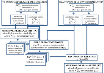
The paper is organized as follows. Section II is devoted to the computation of the field radiated by the transmitting array. The multiple transmitter front ends are analyzed under digitally modulated IF drive as a single non-linear system, with a load consisting of a multi-port antenna described by full-wave EM analysis across the frequency band of interest. To produce the radiated field envelope, the EM results are interfaced with an envelope-oriented harmonic-balance technique modulation-oriented harmonic balance (MHB) based on Krylov-subspace model-order reduction [Reference Rizzoli, Neri, Mastri and Lipparini7]. The far-field radiated by each array element in the presence of the other ones (embedded field) is then used as the input to an advanced 3D radio channel model based on RT, to compute the channel transfer matrix in realistic propagation conditions. This is discussed in Section III. The model accounts for reflection, diffraction, and scattering phenomena experienced by the propagating waves. Computation of geometric aspects has been decoupled from that of frequency-dependent ones. In this way, the former are computed once for all for a given environment, after which multiple channel estimations for different transmitter and receiver parameters may be carried out at virtually no extra cost. Section III also provides an independent validation of this model in an urban propagation environment. Section IV discusses the application of the reciprocity theorem to the multiport receiving antenna under multiple plane-wave incidence to derive a rigorous circuit description of the receiver excitation [Reference Rizzoli6, Reference Rizzoli, Costanzo and Monti8]. The circuit-level non-linear analysis of the multiple receivers treated as a whole may then be again performed by MHB. The whole procedure provides a general and powerful tool for the circuit-level solution of MIMO system problems. As an example, for given transmitter and receiver topologies, the procedure allows the best modulation format and carrier frequency to be systematically determined. Similarly, for a given channel scenario, the method may be used inside a design loop to establish optimum antennas spacing with respect to BER. A block diagram of the simulation procedure is shown in Fig. 1. The detailed meanings of the symbols are explained in the discussion presented in the following sections.
Block diagram of the integrated multi-domain simulation flux for end-to-end MIMO link analysis.

As a performance benchmark, in Section V, we consider the transmission of a 16-QAM signal through a 2 × 2 MIMO link. A quantitative assessment of MIMO performance is obtained by comparing the output BER as well as the received signal constellations and power spectra for several antenna elements distances and for a corresponding single-input single-output (SISO) system in a rich scattering environment. A single MIMO link analysis including all model components may typically require a computational time of the order of 2 h on a 2.8 GHz PC, as is reported in detail in Section V. Finally, a validation of the proposed approach is given by comparison with results generated by time-domain simulation performed by Spectre HDL [9].
II. COMPUTATION OF THE MULTI-ELEMENT TRANSMITTING ANTENNA EXCITATIONS AND FAR-FIELD
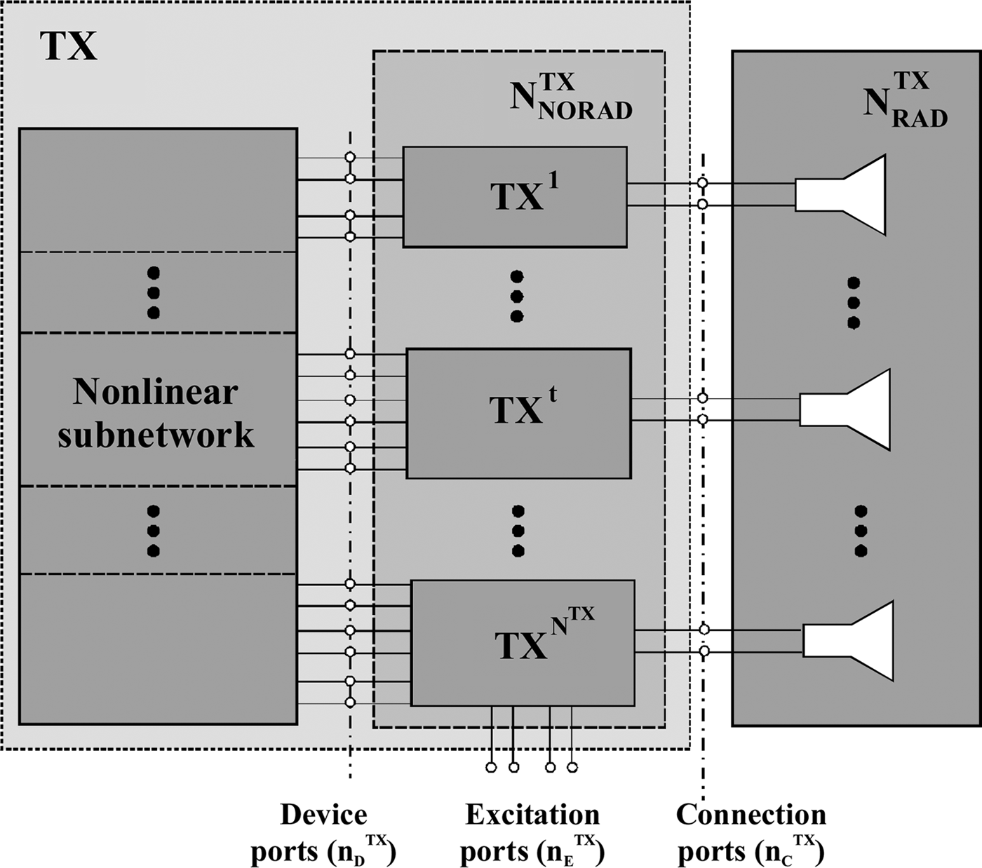
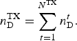
Figure 2 shows a block representation of a MIMO transmitter including the antenna array. The multiple radiofrequency (RF)/microwave transmitter front ends are described as a unique non-linear system consisting of an arbitrary set of non-linear devices interconnected by a linear sub-network. Making use of the piecewise harmonic-balance (HB) technique, the circuit is partitioned into a linear and a non-linear sub-network connected through n DTX ports (device ports), where
Block diagram of a MIMO system (transmitter side).
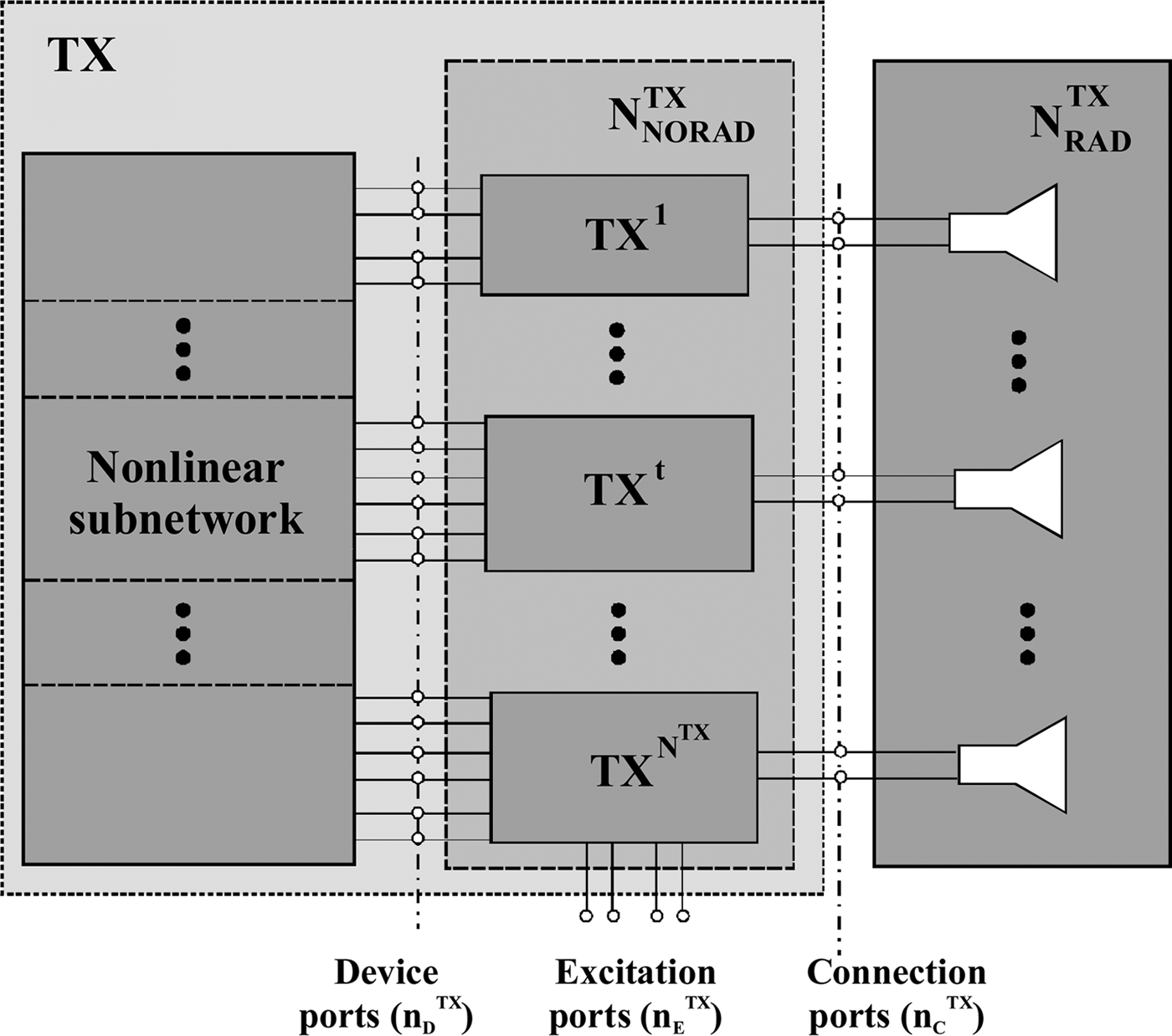
In (1), N TX is the number of transmitters and n Dt is the number of device ports belonging to the tth transmitter. The linear sub-network is referred to as N NORADTX in Fig. 2, and is treated by conventional circuit analysis algorithms. The antenna array is referred to as N RADTX in Fig. 2. It is described layout-wise and analyzed as a linear multiport radiating system by full-wave EM simulation [10] through the finite integration technique (FIT). This analysis simultaneously provides the antenna-scattering matrix and the 3D far-field radiation pattern at all frequencies of interest. The N NORADTX ports may be grouped into three sets, as shown again in Fig. 2, namely, n DTX ports for non-linear device connection, n ETX excitation ports, and n CTX ports for connection to the N RADTX network.
The voltages or currents at the third group of ports (as computed by non-linear analysis of the transmitters) represent the antenna array excitation, which is determined by non-linear analysis in the following way. Let us assume that each transmitter front end is excited by a sinusoidal IF signal of angular frequency ω IFTX and by a sinusoidal local oscillator (LO) of angular frequency ω LOTX. The resulting large-signal regime will be quasi-periodic with spectral lines at all the intermodulation products

where k i's are integer harmonic numbers. A multi-tone harmonic balance analysis of the entire transmission system shown in Fig. 2 (treated as a whole) is carried out by well-known algorithms to simultaneously compute the n DTX vectors of the voltage harmonics at all the transmitter device ports, namely XT,k, at all discrete lines defined by (2). One of the spectral lines is the RF ω RF of the signal to be transmitted, which will be obtained from (2) for some k, say k = s (ω RF = ΩsTX). After carrying out an HB analysis of the transmitter, the complex phasors of the currents flowing out of the n CTX connection ports may be expressed from the linear sub-network equations as

In (3), YDTTX is the (n DTX × n CTX) admittance sub-matrix of the N NORADTX network relating the device ports to the connection ports, YTTTX is the (n CTX × n CTX) admittance sub-matrix seen from the connection ports, and VsTX is the vector of voltage phasors at the connection ports. Furthermore, if YATX is the (n CTX × n CTX) admittance matrix of the multi-element antenna resulting from EM analysis, we have

By combining (3) and (4), we obtain

For the tth array element, with the assumption of free-space propagation, we may then express the total radiated field at ω RF in the following form [Reference Rizzoli, Costanzo, Masotti and Spadoni11]:

where A θt and A ϕt are the scalar components of the normalized field in a spherical coordinate system with origin in the phase center OT of the transmitting array. Such components are generated by EM simulation of the antenna array [10] with a unit-voltage sinusoidal source of angular frequency ω RF connected to the tth port and the remaining ports short-circuited. In this way, the actual frequency-dependent array admittance and the embedded radiation pattern of each array element become available and can be combined with any suitable channel description tool such as the RT algorithm outlined in the following section. It is worth mentioning here that the non-linear multiport approach to transmitter analysis discussed in this section is neither an option nor a minor refinement of previous work. Indeed, due to non-linearity (in particular, of the mixers and the power amplifiers), each transmitter cannot be described by a Thévenin equivalent circuit, i.e., as a voltage source in series with a constant impedance connected to each array port, because a Thévenin equivalent is only available for linear circuits. This is a crucial point, since the performance of a power amplifier designed for a nominal 50 Ω load impedance will change wildly as a function of the actual load, and thus of the inter-element couplings by which the load itself is affected, as shown in Section V (see Fig. 6). In order to account for such effects, a full non-linear analysis of the entire set of transmitters loaded by the multiport antenna array is thus the only available way. Needless to say, a further consequence of circuit non-linearity is the increased spread of the output signal constellation due to non-linear distortion, which gives a significant contribution to BER.
III. THE MIMO RT ALGORITHM
RT models are presently recognized among the most appropriate field prediction tools for the study and planning of radio systems in complex propagation environments. Until now, the main obstacle to the widespread use of RT models has been the need for a detailed 3D database of the environment. However, this requirement is now becoming less and less critical thanks to the steadily increasing availability of digitized maps provided by City Authorities or of commercially available urban maps obtained through aerophotogrammetry. The ability of RT models to predict the multipath pattern and thus the time- and angle-dispersion of the radio signal is especially valuable for studying MIMO systems, which exploit such phenomena to increase the transmission capacity of the radio channel [Reference Paulraj, Gore, Nabar and Bölcskei12]. In this work, a 3D RT model [Reference Degli-Esposti13] has been considered and adapted to MIMO radio channel characterization. A fully 3D vector approach with an embedded diffuse scattering model [Reference Degli-Esposti14] has been adopted to pursue a realistic description of multipath propagation. A coherent representation of the transmitted electric field corresponding to each radio path is provided, as is necessary for MIMO channel characterization. Therefore, the electric field of each radio path (ray) is represented by a complex vector, which depends on the traveled distance and on the interactions (reflections, diffractions, etc.) experienced by the propagating wave.
In the present work, the so-called narrowband array assumption is made: the multipath pattern is assumed to be unique for a given couple of transmit/receive phase-centre positions. By tracing all the rays between the two radio terminals a multidimensional characterization of the array-dependent MIMO channel matrix is derived. Let (θ D, ϕ D) be the initial (departure) direction of the qth ray with respect to a local reference system on the transmitter side. The far-field ETq,t (r D, θD, ϕD; ωRF) radiated by the tth antenna on the qth ray at a reference distance r D (conventionally chosen as 1 m) in the direction (θ D, ϕ D) is computed through (6), and represents the input to the RT algorithm for the ray under consideration. Considering the qth ray path and its interactions (reflection, diffraction, and scattering) with obstacles in terms of interaction losses, spreading factors, and phase shifts, the corresponding field incident on the phase center of the receiving array and referred to the position of its rth element is given by

The field on the left-hand side of (7) is described in a reference frame local to the receiver, with (θ A, ϕ A) representing the direction of arrival of the qth ray and r A the distance at which ERr,q,t (·) is evaluated. The right-hand side of (7) provides an explicit formulation of the propagation effects along the ray. Γq is the scalar spreading factor accounting for the natural attenuation of the field as it propagates along the ray. The qth ray is a piecewise straight line consisting of N q cascaded segments, and s ℓq is the length of the ℓth part of such segments. The exponential factor accounts for the phase shift along the qth ray between the tth transmitting and the rth receiving antenna element. The distance d r,q,t is the overall ray length taking into account the antenna element positions referred to their respective phase centers. Last,  is a dyadic accounting for the effect of ray interactions (reflections, diffractions, etc.), which may be cast in the form
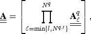
where  is an appropriate dyadic that decomposes the field into orthogonal components at the ℓth interaction point and incorporates the proper interaction coefficients [Reference Balanis15].
The peculiar feature of the adopted RT tool, empowered by the embedded diffuse scattering model, is its ability to accurately describe the multipath nature of the radio link, including its angular spreading, which is fundamental for MIMO performance. Such an ability is assessed in [Reference Kalliola, Laitinen, Vainikainen, Toeltsch, Laurila and Bonek16, Reference Fuschini, El-Sallabi, Degli-Esposti, Vuokko, Guiducci and Vainikainen17], where the model is validated against multidimensional MIMO measurements performed at the Helsinki University of Technology. The adopted RT algorithm has also been shown to yield realistic results in terms of MIMO maximum transmission capacity, as reported in [Reference Vitucci, Degli Esposti and Fuschini18].
IV. COMPUTATION OF THE MULTIPLE-RECEIVER CURRENT EXCITATIONS AND RECEIVER ANALYSIS
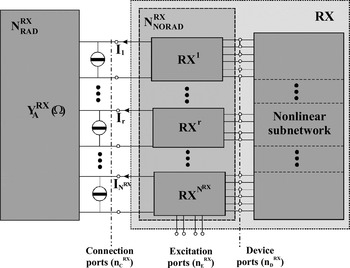
In order to define the channel transfer matrix, the receiver excitation for each incoming ray needs now to be computed. The multiple receiving front end is described by the block diagram shown in Fig. 3. In this case, n CRX connection ports between the N RADRX and the N NORADRX linear sub-networks are used to transfer the signal received by the array to the N RX receivers.
Block diagram of a MIMO system (receiver side).

The receiving array is again characterized by a frequency-domain 3D EM simulation [10], and the corresponding (n CRX × n CRX) admittance matrix YARX is computed at each frequency of interest.
The qth ray radiated by the tth element of the transmitting antenna will excite voltages and currents in the receiver array. In such conditions, the N RADRX network is active, though linear, and may be represented by a Norton equivalent circuit as in Fig. 3, which leads to the circuit equations

In (9), JsRX,q,t is the vector of unknown Norton current sources at the n CRX connection ports, representing the circuit equivalent of the incident field associated with the ray under consideration. In order to find JsRX,q,t , for each array port, we make use of a two-step procedure based on the reciprocity theorem. In the first step, we suppress the incident ray, and operate the receiving array in a transmitting mode. The array is now fed by a unit-voltage source connected to the rth port, and all remaining ports are short-circuited. In such conditions, the normalized radiated far-field ERNr(θ′A, ϕ′A; ωRF) (i.e., the physical field multiplied by r exp(jβr)) and the input admittance parameters Y TTr are computed by EM analysis as discussed in Section II. Here, (θ′A, ϕ′A) are the angular coordinates of the ray direction of arrival in a receiver-referred spherical reference frame. In the second step, we reintroduce the incident field and short-circuit all the antenna ports, so that by (9) the entries of JsRX,q,t coincide with the port currents. Such currents may then be expressed by a straightforward application of the reciprocity theorem. Specifically, for the qth ray radiated by the tth element, the rth entry of JsRX,q,t may be cast in the form:

where • denotes the scalar product. Equation (10) can exactly compute the Norton equivalent sources for an arbitrarily polarized receiving array excited by an arbitrarily polarized incident field having an equally arbitrary direction of arrival, which allows a general 3D channel model to be generated. Note that the use of the scalar reception pattern of the receiving antenna is not sufficient for this purpose. A superposition of the contributions (10), spanning all the incoming rays, finally yields the current source at the rth port:
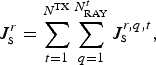
where N RAYt is the number of rays originating from the tth transmitter element. This method allows the actual receiver excitations to be exactly computed with the multiple receiver terminated by the EM-generated frequency-dependent receiver array impedance matrix. For a given channel scenario, this procedure may thus be used to efficiently compute the impact of different antenna structures and relative positions on receiver performance.
By combining (11), (10), (7), and (6), we may now express each current J sr (1 ≤ r ≤ N RX) as a linear combination of the voltages V st (1 ≤ t ≤ N TX). In other words, we have established a linear map between the vector JsRX of the receiver excitation currents at the receiving antenna ports and the vector VsTX of the transmitting antenna excitation voltages. If we cast this map in the form

the complex (N RX × N TX) matrix H(ω RF) represents our definition of the channel transfer matrix.
As a clarifying example, for a simple 2 × 2 MIMO link with only two non line-of-sight (NLOS) rays (one for each transmitter), (12) takes on the explicit form
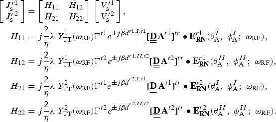
In (13) superscripts ‘t1, t2’ and ‘r1, r2’ are the transmitted and incident rays indexes.
The channel transfer matrix H(ω RF) defined by (12) simultaneously accounts for selective fading due to 3D multipath propagation in the channel, for all EM couplings existing between the transmitting and receiving antennas, and for polarization mismatches between incident field and receiving antennas. The latter are due to power transfer between cross polarizations taking place in the channel, as shown in Section IV, and possibly to different antenna structures.
At this stage, we write the receiver N NORADRX equations in a way similar to (3), namely

where the superscript “RX” stands for “receiver” and the meanings of all quantities are otherwise identical to those appearing in (3). Equations (9), (14), and the non-linear subnetwork equations may now be handled by well-known algorithms [Reference Rizzoli, Neri, Mastri and Lipparini7] to produce a full non-linear analysis of the receiver under modulated RF drive.
V. BENCHMARK SIMULATION OF A MIMO LINK
A) Effect of antennas spacing on multiple front end performance
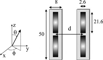
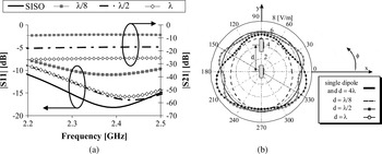
A 2 × 2 MIMO link designed for wireless local area network (WLAN) application at 2.437 GHz is considered first. The transmitter consists of two single-conversion front ends with a total of 196 device ports and 2370 internal nodes. The receiver consists of two image-rejection front ends with 416 device ports and 2490 nodes. The antennas – similar to the one proposed in [Reference Konanur, Gosalia, Krishnamurthy, Hughes and Lazzi5] – are two parallel groundless half-wave dipoles built on Taconic RF-60 substrate (ɛ r = 6.15, tanδ = 0.0028), and are analyzed by [10]. The array is depicted in Fig. 4. The results in terms of scattering parameters of the array and of the radiation pattern of each element in the presence of the other one are plotted in Figs 5(a) and 5(b), respectively, and are compared with similar quantities for the standalone dipole.
Printed dipole array (dimensions in mm).

(a) Scattering parameters of the two-port transmitting antenna for different dipoles spacing (d) and for the standalone dipole (SISO). (b) H-plane radiation pattern of a standalone dipole and of one dipole in the presence of the other for different inter-element spacing.

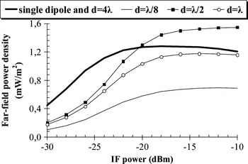
The reflection coefficients exhibit resonance frequency shifts up to 2%, and a mutual coupling up to −10 dB is observed. The latter produces a remarkable deformation of the H-plane radiation pattern with respect to the standalone dipole, as is evident from Fig. 5(b). These results clearly show that theoretical approaches to MIMO analysis based on the assumption of isolated antennas do not represent a valid description of real-world compact systems. Indeed, antenna interactions are significant even at distances d comparable with the wavelength. In turn, transmitter performance is strongly dependent on couplings between antennas. Indeed, due to couplings transmitter loads are a function of antenna distance, and so is the transmitter performance, according to the discussion presented in Section II. This effect is demonstrated in Fig. 6, where the far-field radiated power density ET•ET*/2η evaluated by (6) is plotted against IF input power as a function of dipoles spacing. For the sake of comparison, the same analysis is repeated for an identical standalone transmitter. The transmitter gain compression curve is found to be strongly influenced by the presence of neighboring array elements.
Transmitter gain compression curve for different dipoles spacing.

Frequency-dependent antenna interactions are widely recognized to have a primary influence on MIMO channel capacity [Reference Rosengreen and Kildal2, Reference Wallace and Jensen4]. Figure 6 shows that they also play an essential role in determining the linear and non-linear transmitter performance [Reference Rizzoli, Costanzo, Masotti and Spadoni19]. Indeed, such performance may be enhanced or degraded with respect to the SISO case depending on antennas spacing.
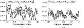
We then investigate the effects of receiving antennas spacing on the channel transfer matrix in a rich scattering propagation scenario. The first analysis is carried out under RF sinusoidal excitation at 2.437 GHz without modulation. The transmitting antenna elements are kept at a fixed distance of 6.16 cm, corresponding to half the wavelength. The channel scenario needs more than 3000 propagation rays. Figures 7(a) and 7(b) compare the magnitudes of the entries of the channel transfer matrix H(ω RF) for antennas spacing of 3λ/8 and λ/8, respectively. The two plots clearly show that for the chosen propagation scenario selective fading may be effectively compensated by suitable antennas spacing, since larger values of the H(ω) entries automatically result in channel capacity improvement [Reference Rosengreen and Kildal2, Reference Wallace and Jensen4].
Magnitudes of the channel transfer matrix entries: (a) for 3λ/8 dipoles spacing and (b) for λ/8 dipoles spacing.

The next step is to optimize the antennas spacing for the given channel scenario and for a real-world digitally modulated signal. The selected modulation format is 16-QAM at a bit rate of 1.28 Mb/s. The system output signal is computed by in-phase combining the output signals of the two receivers (equal-gain combining technique). The adopted performance index is the BER in the presence of thermal noise described by an Additive White Gaussian Noise (AWGN) model. The noise calculation has been based on the assumption that noise received by the antenna is the dominant noise contribution. According to the well-known theory of linear network noise, this contribution is modeled by a set of equivalent noise current sources connected in parallel to the receiving antenna ports, and thus to the current sources J sr given by (11), which represent the useful signal. The noise sources have Gaussian statistics, and their correlation matrix is proportional to the real part of the multiport antenna admittance matrix trough an equivalent antenna noise temperature [Reference Rizzoli, Mastri and Masotti20]. BER evaluation is carried out at the circuit level by the same technique introduced in [Reference Rizzoli, Costanzo, Masotti and Spadoni11] for the SISO case. Briefly, once all the system parameters have been specified, the input modulating signal is described as a random sequence of bits, and the output sequence is evaluated by the envelope-transient technique in a time slot of finite length, say a few hundred bits. This I/O information generated by simulation is used to train an Artificial Neural Network (ANN) model of the link in the given operating conditions. The ANN model is then used to cheaply generate an output sequence of several million bits that is used to compute BER by direct comparison with the input sequence [Reference Rizzoli, Costanzo, Masotti and Spadoni11, 21]. Note that a full frequency-domain noise analysis for non-linear circuits including the LO noise contribution in receiver front ends has been previously demonstrated [Reference Rizzoli, Mastri and Masotti20, Reference Rizzoli, Costanzo, Masotti and Mastri22]. However, handling LO noise inside a rigorous non-linear circuit-level BER analysis of the kind outlined above is not straightforward. This topic is currently under investigation, and the results will be reported elsewhere.
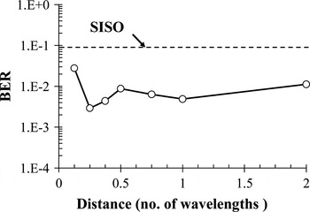
Figure 8 shows the results obtained for a fixed signal-to-noise ratio (SNR) of 10 dB at the receiver input. Such results are based on a sequence of 1 600 000 samples generated by an ANN link model trained by a sequence of 512 simulated samples. For the scenario under consideration, the optimum antennas spacing (d ≈ λ/4) results in a BER reduction of about two orders of magnitude with respect to the SISO case. Note that the optimum performance is acceptable in spite of the low SNR.
Estimated BER of a MIMO link as a function of dipoles spacing.

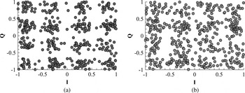
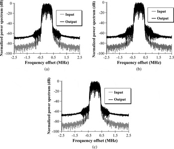
These results are visually confirmed by comparison of the output signal constellations of the MIMO link with optimal (Fig. 9(a)) and non-optimal (Fig. 9(b)) antennas spacing. The two main sources of the signal corruption observed in Figs 9 and 10 are noise and in-band linear distortion. Non-linear distortion is also somewhat improved by the MIMO arrangement with respect to the corresponding SISO system (same circuits and channel), but the effect is not as dramatic as for BER. This is evident by comparison of Figs 10(a) and 10(b), where the input and output signal spectra are shown (in the absence of noise) for the MIMO system with optimal antennas spacing and for the corresponding SISO system, respectively. The adjacent-channel power ratio (ACPR) is reduced by about 4 dB in the MIMO case. Also, for a MIMO system, non-linear distortion is almost independent of antennas spacing. As an example, the output spectrum reported in Fig. 10(c) for a case of non-optimal antennas spacing (d ≈ λ/8) exhibits a distortion level quite similar to that observed in Fig. 10(a) (the change in ACPR is <1 dB). A full non-linear/EM multi-tone analysis of the 2 × 2 MIMO link requires about 100 min of CPU time on a 2.8 GHz PC. Within this budget, about 40% of the time is taken by the EM simulation of the transmitting and receiving antenna arrays, about 45% by the computation of the RT-based field prediction model, and the remaining 15% by the non-linear analysis of the transmitter and receiver front ends.
Output signal constellation of the MIMO link: (a) with optimal antennas spacing (d ≈ λ/4) and (b) with non-optimal antennas spacing (d ≈ λ/8).

Normalized power spectra for: (a) a MIMO link with optimal dipoles spacing (ACPR is about −50.1 dBc); (b) the SISO link corresponding to (a) (ACPR is about −46.2 dBc); (c) a MIMO link with non-optimal dipoles spacing (d ≈ λ/8) (ACPR is about −49.2 dBc).

B) Validation by comparison with time-domain results
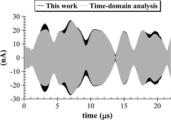
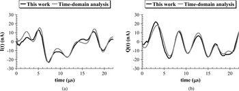
For validation purposes, in this section, we present a comparison of the MIMO link analysis results produced by our technique with those generated by time-domain analysis making use of Spectre HDL [9]. For this purpose, the frequency-domain channel model discussed in Section III is converted into a time-domain user-defined component in Spectre HDL format according to the technique discussed in [Reference Rizzoli, Costanzo, Mastri and Neri23]. This procedure is very demanding in terms of CPU time, since it basically relies upon a time-domain convolution. The other bottleneck is the slow (1.28 Mb/s) modulation of the 2.437 GHz RF carrier, which generates the need for an unreasonably large number of time-domain integration steps. We have thus been forced to work out a tradeoff between accuracy and CPU time by limiting the number of frequency-domain sampling points for the entries of the channel transfer matrix, and of time-domain sampling points in the integration process. Even so, the CPU time required to compute the results reported in Figs 11 and 12 by time-domain analysis was about 22 000 times longer than the CAD procedure discussed in the previous sections. The benchmark quantity used for comparison is the Norton equivalent current source J s1 defined by (11). The analysis is limited to a 64-bit time slot. Figure 11 provides a visual comparison of the time-domain waveforms of this current computed in the presence of digital modulation. More quantitative comparisons are provided in Figs 12(a) and 12(b), showing the in-phase (a) and quadrature (b) components of the complex envelope.
Time-domain waveform of the modulated current source J s1 for a 2 × 2 MIMO link with optimal dipoles spacing (64-bit time slot).

In-phase (a) and quadrature (b) component of the complex envelope for the modulated current source J s1.

In all cases the agreement may be considered very satisfactory, which provides a reliable validity check for our MHB analysis procedure.
In order to validate the BER computation procedure, we finally tried to generate results similar to those reported in Fig. 8 by commercial software. As in Section V.A, a 16-QAM modulated input signal was considered, with a bit rate of 1.28 Mb/s and a 10 dB SNR at the receiver ports. This turned out to be an awkward task, because a direct time-domain approach was found to be impossible due to impractically large CPU time requirements. We thus resorted to a system simulator. In order to get best accuracy within the capabilities of system-oriented software, we described each transmitter and receiver by a behavioral model derived by HB analysis, and the channel description was input as a user-defined component characterized by the transfer equations (12) at the data entry level. In this way, the results provided by the system simulator were found to agree with those reported in Fig. 8 with a maximum discrepancy of ±10% for d ≥ λ. However, for closely spaced antennas, the commercial simulator was unable to reproduce the dependence of the transmitter performance on antenna couplings, and the BER results were grossly in error.
VI. CONCLUSION
The computer-aided simulation of MIMO links is a formidable problem that is normally tackled by a handful of simplifying assumptions whose combined impact on the overall analysis accuracy may be difficult to establish. The highest modeling difficulties are encountered when antennas must be placed in close proximity of each other, e.g., due to space limitations. Indeed, in such cases, antenna couplings may critically affect system performance. In this paper, we propose a solution approach based on the combination of state-of-the art software tools and of basic EM theory in order to systematically handle each subsystem as well as the interactions among subsystems in a most general and accurate way. Key aspects are the EM characterization of the transmit/receive arrays, the analysis of transmit/receive front ends by non-linear CAD methods, the RT-based channel model, and the description of the EM field as the actual physical link between the transmitter and receiver side. The proposed technique is intended as a starting point, that is, an initial kernel for the development of a new generation of general-purpose software tools for RF link analysis. Several aspects still have to be improved or developed, and will be the topics of future work. As a representative example, time-domain statistical channel models may be the way to go for mobile MIMO links, and will have to be interfaced with the other analysis tools taking advantage of the hybrid time-frequency domain representation already used to describe digitally modulated signals. The potential applications cover virtually any kind of link operating under complex, highly inhomogeneous propagation conditions, e.g., from mobile communications to data transfer from precision mechanical instrumentation in a workshop environment.
 Vittorio Rizzoli joined the University of Bologna as a Full Professor of electromagnetic fields in 1980. His research interests are in the areas of non-linear microwave circuit simulation and design (with emphasis on modern CAD techniques for large-size problems), empirical device modeling, and electromagnetic design of integrated circuits. Professor Rizzoli is a member of the Editorial Board of IEEE MWCL, and of Wiley's IJ of RF and Microwave CAE. He is also a member of the Paper Review Board of “Electronics Letters”. In 1990/92, he served as the Distinguished Microwave Lecturer of IEEE MTT-S for Region 8, lecturing in Europe, USA and Middle East on “Simulation and Design of Nonlinear Microwave Circuits”. In 1994, he was elected Fellow of the IEEE with the citation “For Contributions to the Simulation and Design of Nonlinear Microwave Integrated Circuits”. In 2005/2006, he served as an Associate Editor for the IEEE Transactions on MTT.
 Alessandra Costanzo received a Doctor degree in Electrical Engineering (magna cum laude) from the University of Bologna, Italy, in 1987. Since 2001, she has been Associate Professor of electromagnetic fields at the University of Bologna, Polo di Cesena. She has co-authored more than 80 scientific publications on International Journals and conferences and one book. She holds two international patents. Her research activities have focused on: electro-thermal characterization and modeling of RF/microwave non-linear devices; broadband design of active microwave-integrated circuits, including autonomous circuits and systems for electrical stability, and noise performance. She has worked on an innovative software platform based on non-linear and electromagnetic co-simulation, for analysis of self-oscillating circuits and systems, including active antennas, excited by digitally modulated sources. She is involved in the development of structural health monitoring sensors based on semi-passive RF-ID tags and microwave interference. She contributes to the European project SOFIA (Smart Objects for Intelligent Applications).
 Diego Masotti received the Dr Ing. degree in Electronic Engineering and the Ph.D. degree in Electric Engineering from the University of Bologna, Bologna, Italy, in 1990 and 1997, respectively. In October 1998, he joined the Department of Electronics Computer Science and Systems of the University of Bologna as a Research Associate of electromagnetic fields. His research interests are in the areas of non-linear microwave circuit simulation and design (with emphasis on modern CAD techniques for large-size problems), empirical device modeling, and electromagnetic design of integrated circuits. Dr Masotti is a member of the Paper Review Board of the IEEE Transaction on Microwave Theory and Techniques, IEEE Communication Letters, IET-Circuit Devices & Systems, since 2004, 2010, and 2011, respectively.
 Martino Aldrigo obtained the Dr Ing. degree in Telecommunication Engineering from the University of Bologna, Italy, in 2009. He is currently involved in a Ph.D. programme at the same University, concerning the design and project of antennas and RF systems for wearable and implantable ultra low-power applications.
 Francesco Donzelli received the Dr Ing degree and the Ph.D. degree in Telecommunication Engineering from the University of Bologna, Italy in 2007 and 2011, respectively. His current research interests focus on characterization of RF links by the combination of non-linear, electromagnetic, and propagation analysis techniques, but comprise also the project and realization of low-power rectennas for energy harvesting from wireless sources and the study and stability analysis of micro-electromechanical devices and employment on common microwave devices.
 Vittorio Degli Esposti received the Dr Ing. degree in Electronic Engineering and the Ph.D. degree from the University of Bologna in 1989 and 1994, respectively. From 1989 to 1990, he was with Siemens Telecomunicazioni, Milan, involved in research on high-speed optical fiber communication systems. Since November 1994, he has been with the Dipartimento di Elettronica, Informatica e Sistemistica (DEIS) of the University of Bologna as a Research Associate. He has been a visiting researcher in 1998 at the Polytechnic University, Brooklyn, New York (USA), working with Professor H.L. Bertoni on diffuse scattering models for urban propagation prediction. His current research interests are in the fields of mobile radio systems, applied electromagnetics, diffuse scattering models, ray tracing, and advanced statistical models for urban field prediction. Dr Degli Esposti participated in the European Cooperation Projects COST 231, COST 259, and COST 273. He is member of the IEEE Antennas and Propagation.