



1 Introduction
Use of capillary tubes is widespread in a range of health and industrial applications, for example, in the studies of film instability (Goren Reference Goren1962; Rossen Reference Rossen2000; Duclaux, Clanet & Quéré Reference Duclaux, Clanet and Quéré2006), wetting (Washburn Reference Washburn1921; Hoffman Reference Hoffman1975; Walls, Dequidt & Bird Reference Walls, Dequidt and Bird2016; Zhao et al. Reference Zhao, Alizadeh Pahlavan, Cueto-Felgueroso and Juanes2018), blood flow (Goldsmith & Spain Reference Goldsmith and Spain1984; Pries, Neuhaus & Gaehtgens Reference Pries, Neuhaus and Gaehtgens1992) and oil recovery (Blunt Reference Blunt2001; Morrow & Mason Reference Morrow and Mason2001; Patzek & Kristensen Reference Patzek and Kristensen2001). In many of these applications, precise control of the surface properties of the capillary tubes is critical. Here, we demonstrate that such control is possible through the deposition of thin layers of functional polymers via spin coating (Emslie, Bonner & Peck Reference Emslie, Bonner and Peck1958; Scriven Reference Scriven1988), a technique that has not previously been explored for coating capillary tubes.
The prevalent approach to coating the inner wall of a capillary tube dates back to Taylor (Reference Taylor1961). A tube is filled with viscous liquid, which is subsequently expelled by air at a prescribed flow rate. As the air bubble propagates through the tube, a liquid film of uniform thickness is left on the wall of the tube. When  $Ca\ll 1$, the thickness
 $h$ can be estimated from Bretherton’s law (Bretherton Reference Bretherton1961) as
 $h\sim RCa^{2/3}$, where
 $Ca=\unicode[STIX]{x1D707}u/\unicode[STIX]{x1D70E}$ is the capillary number,
 $\unicode[STIX]{x1D707}$ the liquid viscosity,
 $u$ the bubble velocity,
 $\unicode[STIX]{x1D70E}$ the surface tension and
 $R$ the tube radius. This method has been used extensively to generate annular films of controlled thickness (Goren Reference Goren1962; Aussillous & Quéré Reference Aussillous and Quéré2000; Duclaux et al. Reference Duclaux, Clanet and Quéré2006). While it is well suited to generating relatively thick films at moderate bubble speeds, practical difficulties in maintaining very low gas flow rates may preclude the deposition of films of uniform thickness at very low displacement rates. In particular, syringe pumps operating at low constant injection rates are known to have stepper-motor-induced pressure fluctuations (Li et al. Reference Li, Mak, Sauret and Shum2014; Zeng et al. Reference Zeng, Jacobi, Beck, Li and Stone2015).
Here, we explore centrifugally forced deposition of viscous liquids in capillary tubes, which offers an easily accessible alternative to Taylor’s method that is particularly advantageous for micron-scale films. In § 2, we describe the details of the experimental set-up. We present theoretical arguments for the early and late-time flow dynamics in § 3. Control over the film thickness allows for manipulation of the time scale of the subsequent Rayleigh–Plateau instability described in § 5. We thus present methods for generating both cylindrical and corrugated coatings on capillary tubes with a curable polymer, and point to potential applications in § 6.
2 Experimental method
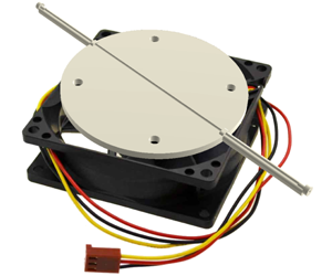
We repurpose a computer fan as a spin coater: the blades of the fan are removed and a three-dimensionally printed platform for holding capillary tubes is attached, centred at the spin axis (figure 1a). The fan is connected through an Arduino board to MATLAB, where we fix the angular velocity at  $854\pm 10$ r.p.m. for all of the experiments presented below.
(a) Diagram of the computer fan repurposed as a spin coater. (b) Schematic of the capillary tubes filled with liquid slugs, spun at angular velocity  $\unicode[STIX]{x1D714}$. (c) Schematic of the slug-flow regime. (d) Schematic of the film-thinning regime. 3-D, three-dimensional.

First, we explore how liquid slugs move within the spinning capillary tubes with high speed imaging (see the supplementary material, available at https://doi.org/10.1017/jfm.2019.1072, Movie 1). We introduce 20 mm long liquid slugs into the capillary tubes (Hilgenberg borosilicate glass, 75 mm in length,  $290~\unicode[STIX]{x03BC}\text{m}$ inner radius), place them onto the spin-coating platform, as shown in figure 1(b), and spin. We track the slug length
 $l(t)$ and slug-centre distance
 $x_{c}(t)$ from the spin axis (figure 2a,b). As the slug moves outwards, it leaves a film of liquid behind, reducing the slug length
 $l$ as
 $x_{c}$ increases. Notably, the evolution of
 $l$ with
 $x_{c}$ is nearly independent of the liquid viscosity (figure 2b), which means that the film thickness profile deposited by the slug is also independent of viscosity. Furthermore,
 $x_{c}$ grows exponentially with time (figure 2a), which makes the slug-flow regime very brief. Both of these observations are to be rationalized in § 3.2.
In the second set of experiments, we explore the thinning dynamics of the liquid films on the capillary tube walls arising after the slug has exited the tube. We introduce a sufficient volume of liquid into the capillary tubes such that the film is deposited throughout the tube. The excess liquid is allowed to escape from the outer end of the tube. The thickness of the liquid film left on the walls is estimated from the weight difference of the dry and coated tubes. This is done in groups of ten capillary tubes – weights are measured with an Ohaus Explorer EX225D scale, which allows 0.1 mg precision, corresponding to sub-micrometre precision in the final film thickness.
When capillary tubes are spun at sufficiently high angular speed, the amount of liquid within the tubes drops sharply at first, then slowly approaches its long-time limit. The experimental results of spin-coating capillary tubes with different liquids (50–1000 cSt silicone oils and NOA81) are reported in figure 3(a). Silicone oils and NOA81 show similar trends, with the value of the final thickness increasing with viscosity.
We rationalize these observations with theoretical models developed in the next section, where we distinguish two flow modes: slug motion and film thinning. We find the characteristic time scales of these two modes and show that the temporal evolution evident in figure 3 is largely associated with the slow thinning of the viscous films. Note that we do not attempt to model the film thinning of NOA81, as its rheology is yet to be fully characterized. We found that its viscosity ( ${\sim}240$ cSt) increases with shelf life and that it exhibits non-Newtonian behaviour at low film heights. As a result, the polymer is primarily used here to illustrate the possibility of making channels with wavy walls in § 6.
(a) Exponential change in the slug-centre position  $x_{c}$ with time, where the time scales (inverse of the slope) are [
 $0.9,3.2,4.0,7.5$] s for [
 $50,350,500,1000$] cSt, respectively. Here
 $x_{0}$ is the initial coordinate of the slug centre. (b) Measurements of the slug length
 $l$ with
 $x_{c}$ suggest viscosity-independent film-deposition profiles (see appendix A for a discussion of the deviation of the 50 cSt oil curve).

(a) Temporal evolution of the deposited film thickness long after the slug motion: measurements are denoted with circles (and squares), theory with solid lines. (b) Film thickness evolution of 1000 cSt silicone oil spun at 651, 854 and 1285 r.p.m. (c) Collapse of the data from figure 3(a) and figure 3(b) using (3.11). Each point corresponds to 10 spin-coating experiments, with over 350 total coated tubes.

3 Theory
Consider a capillary tube, containing a liquid slug of density  $\unicode[STIX]{x1D70C}$ and dynamic viscosity
 $\unicode[STIX]{x1D707}$, that is spun at a prescribed angular speed
 $\unicode[STIX]{x1D714}$ (figure 1c). As the slug moves outwards, it deposits a liquid film on the tube walls. We consider the control region containing the slug only. Three forces may be significant in this configuration: the capillary (
 $F_{cap}$), viscous (
 $F_{visc}$) and centrifugal (
 $F_{centr}$) forces. The capillary force can be estimated from the different end curvatures of the liquid slug; the Laplace pressure difference on its ends opposes the outward motion (Bico & Quéré Reference Bico and Quéré2001):
 $$\begin{eqnarray}\displaystyle F_{cap}=-\unicode[STIX]{x03C0}R^{2}\frac{2\unicode[STIX]{x1D70E}}{R}+\unicode[STIX]{x03C0}(R-h_{0})^{2}\frac{2\unicode[STIX]{x1D70E}}{R-h_{0}}=-2\unicode[STIX]{x03C0}\unicode[STIX]{x1D70E}h_{0}, & & \displaystyle \nonumber\end{eqnarray}$$
where  $h_{0}$ is the characteristic thickness of the film deposited by the slug motion, and we assume a completely wetting liquid. The viscous force associated with Poiseuille flow can be estimated from the drag on the tube walls,
 $$\begin{eqnarray}\displaystyle F_{visc}=-2\unicode[STIX]{x03C0}Rl(t)\frac{4\unicode[STIX]{x1D707}}{R}{\dot{x}}_{c}=-8\unicode[STIX]{x03C0}\unicode[STIX]{x1D707}l(t){\dot{x}}_{c}, & & \displaystyle \nonumber\end{eqnarray}$$
where  $l(t)$ is the liquid slug length,
 $x_{c}$ the position of the slug centre and
 ${\dot{x}}_{c}$ its velocity. Finally, the centrifugal force acting at the slug can be expressed as
 $$\begin{eqnarray}\displaystyle F_{centr}=\int _{x_{c}-l/2}^{x_{c}+l/2}\unicode[STIX]{x1D70C}\unicode[STIX]{x03C0}R^{2}\unicode[STIX]{x1D714}^{2}x\,\text{d}x=\unicode[STIX]{x1D70C}\unicode[STIX]{x03C0}R^{2}\unicode[STIX]{x1D714}^{2}l(t)x_{c}. & & \displaystyle \nonumber\end{eqnarray}$$
Therefore, the motion of the slug is governed by  $\text{d}(m{\dot{x}}_{c})/\text{d}t=F_{cap}+F_{visc}+F_{centr}$, from which it follows that
 $$\begin{eqnarray}\displaystyle \frac{{\dot{m}}{\dot{x}}_{c}}{m}+\ddot{x}_{c}=-\frac{2\unicode[STIX]{x1D70E}h_{0}}{\unicode[STIX]{x1D70C}l(t)R^{2}}-\frac{8\unicode[STIX]{x1D707}{\dot{x}}_{c}}{\unicode[STIX]{x1D70C}R^{2}}+\unicode[STIX]{x1D714}^{2}x_{c}. & & \displaystyle \nonumber\end{eqnarray}$$
We neglect  ${\dot{m}}{\dot{x}}_{c}$ since
 ${\dot{m}}{\dot{x}}_{c}/m\ddot{x}_{c}=\unicode[STIX]{x1D70C}2\unicode[STIX]{x03C0}Rh_{i}{\dot{x}}_{c}^{2}/\unicode[STIX]{x1D70C}\unicode[STIX]{x03C0}R^{2}l\ddot{x}_{c}=(h_{i}/R)(2{\dot{x}}_{c}^{2}/\ddot{x}_{c}l)\sim (h_{i}/R)(l^{2}/\unicode[STIX]{x1D70F}_{inert}^{2}/l^{2}/\unicode[STIX]{x1D70F}_{inert}^{2})=h_{i}/R\ll 1$, where
 $h_{i}$ is the film thickness deposited in the inertial regime and
 $\unicode[STIX]{x1D70F}_{inert}$ the inertial time scale (see § 3.1). Furthermore,
 $F_{cap}/F_{centr}=(h/R)(2\unicode[STIX]{x1D70E}/\unicode[STIX]{x1D70C}lx_{c}R\unicode[STIX]{x1D714}^{2})\sim 10^{-2}(h/R)\ll 1$; hence, we may safely neglect the contribution of the capillary force from this point on. The force balance then reduces to
 $$\begin{eqnarray}\displaystyle \ddot{x}_{c}=-\frac{8\unicode[STIX]{x1D707}{\dot{x}}_{c}}{\unicode[STIX]{x1D70C}R^{2}}+\unicode[STIX]{x1D714}^{2}x_{c}. & & \displaystyle\end{eqnarray}$$
We proceed by separating the slug dynamics (figure 1c) into early inertial (§ 3.1) and late viscous (§ 3.2) regimes. The subsequent thinning of the film on the tube walls (figure 1d) is described thereafter.
3.1 Inertial slug flow ( $t<\unicode[STIX]{x1D70C}R^{2}/8\unicode[STIX]{x1D707}$)

When the flow is dominated by inertia, the viscous term in (3.1) can be neglected and the motion of the slug is governed by
 $$\begin{eqnarray}\displaystyle \ddot{x}_{c}=\unicode[STIX]{x1D714}^{2}x_{c}. & & \displaystyle\end{eqnarray}$$
The position of the slug can be expressed as  $x_{c}(t)=x_{0}\cosh (\unicode[STIX]{x1D714}t)$, where
 $x_{0}$ is the initial coordinate of the slug centre.
The inertial flow persists until the boundary effects diffuse across the tube and motion becomes viscosity dominated. The cross-over between the two regimes occurs when the viscous term becomes comparable to inertia and  $\ddot{x}_{c}\sim 8\unicode[STIX]{x1D707}{\dot{x}}_{c}/\unicode[STIX]{x1D70C}R^{2}$, which allows us to establish the characteristic time for the inertial flow as
 $\unicode[STIX]{x1D70F}_{inert}\equiv \unicode[STIX]{x1D70C}R^{2}/8\unicode[STIX]{x1D707}$. The characteristic time scale of inertial slug flow ranges between
 $10^{-5}$ and
 $2\times 10^{-4}~\text{s}$ for the silicone oils used in our study. Notably, these times correspond to the oil slug displacements between 8 nm and
 $3~\unicode[STIX]{x03BC}\text{m}$ (for 1000 cSt and 50 cSt oils, respectively): in our experiments, the system quickly switches to the viscosity-dominated regime.
3.2 Viscous slug flow ($\unicode[STIX]{x1D70C}R^{2}/8\unicode[STIX]{x1D707}<t<8\unicode[STIX]{x1D707}/\unicode[STIX]{x1D70C}\unicode[STIX]{x1D714}^{2}R^{2}$)

In the viscosity-dominated slug regime, we neglect the inertial terms so that (3.1) reduces to
 $$\begin{eqnarray}\displaystyle \frac{8\unicode[STIX]{x1D707}{\dot{x}}_{c}}{\unicode[STIX]{x1D70C}R^{2}}=\unicode[STIX]{x1D714}^{2}x_{c}, & & \displaystyle\end{eqnarray}$$
and the slug position can be expressed as  $x_{c}=x_{0}\text{e}^{(\unicode[STIX]{x1D70C}\unicode[STIX]{x1D714}^{2}R^{2}/8\unicode[STIX]{x1D707})t}$. The characteristic time for the slug flow is
 $\unicode[STIX]{x1D70F}_{slug}\equiv 8\unicode[STIX]{x1D707}/\unicode[STIX]{x1D70C}\unicode[STIX]{x1D714}^{2}R^{2}$, which corresponds to 0.6 and 11.7 s for 50 and 1000 cSt silicone oils, respectively. These times are in close agreement with the experimental measurements of the slug-flow time scale reported in figure 2(a).
As the liquid slug moves through the tube, it deposits a film on the wall. This film is also subject to centrifugal forces; however, we neglect its thinning within the relatively brief time frame of the viscous slug flow (an approximation to be justified a posteriori by comparison with the thinning time scale). Then, the thickness of the deposited film can be estimated from Bretherton’s scaling (Bretherton Reference Bretherton1961) as
 $$\begin{eqnarray}\displaystyle h_{0}(x)\sim RCa^{2/3}=R\left(\frac{\unicode[STIX]{x1D707}{\dot{x}}}{\unicode[STIX]{x1D70E}}\right)^{2/3}=R\left(\frac{\unicode[STIX]{x1D70C}\unicode[STIX]{x1D714}^{2}R^{2}}{8\unicode[STIX]{x1D70E}}x\right)^{2/3}. & & \displaystyle\end{eqnarray}$$
Notably, this thickness is independent of the liquid viscosity, in agreement with the experimental data in figure 2(b).
As the slug speed increases, the  $Ca$ increases from 0 to approximately 0.8 in our experiments. Therefore, Bretherton’s scaling (3.4) is only applicable while the slug is near the inner end of the tube, where
 $Ca\ll 1$. While a more accurate scaling of
 $h_{o}(x)\sim R(Ca^{2/3}/(1+Ca^{2/3}))$ can be used for
 $Ca$ between 0.01 and 1 (Aussillous & Quéré Reference Aussillous and Quéré2000), we demonstrate in § 4 that the late-time thinning profile is not sensitive to the film thickness profile left after the viscous slug-flow regime. This is consistent with the work of Emslie et al. (Reference Emslie, Bonner and Peck1958). Therefore, we use the expression (3.4) as a leading-order approximation for simplicity in this work.
3.3 Film thinning ($t>8\unicode[STIX]{x1D707}/\unicode[STIX]{x1D70C}\unicode[STIX]{x1D714}^{2}R^{2}$)

In the late-time flow regime, we start with the film thickness profiles from (3.4). Subsequent thinning of the film is resisted predominantly by the viscosity of the liquid. As the liquid film thins, viscous resistance balances the centrifugal force,  $F_{visc}\sim F_{centr}$, as is the case in the spin coating of flat surfaces (Emslie et al. Reference Emslie, Bonner and Peck1958). Then, in the absence of inertia and provided that
 $h\ll R$, we can invoke the lubrication approximation, according to which
 $$\begin{eqnarray}0=\unicode[STIX]{x1D707}\frac{\unicode[STIX]{x2202}^{2}u}{\unicode[STIX]{x2202}r^{2}}+\unicode[STIX]{x1D70C}\unicode[STIX]{x1D714}^{2}x.\end{eqnarray}$$
By imposing the no-slip boundary condition at the wall and zero shear stress at the liquid surface, we obtain from direct integration of (3.5) the velocity field:  $u(x,r)=(\unicode[STIX]{x1D70C}\unicode[STIX]{x1D714}^{2}x/\unicode[STIX]{x1D707})(-r^{2}/2+r(R-h(x))+R(h(x)-R/2))$. Thus, we estimate the volume flow rate as
 $$\begin{eqnarray}q(x)=\int _{R-h(x)}^{R}2\unicode[STIX]{x03C0}ru(x,r)\,\text{d}r=\frac{\unicode[STIX]{x03C0}\unicode[STIX]{x1D70C}h(x)^{3}\unicode[STIX]{x1D714}^{2}x}{12\unicode[STIX]{x1D707}}(8R-5h(x)).\end{eqnarray}$$
Conservation of mass in a representative section of the liquid film (see figure 1d) yields  $q(x)-q(x+\unicode[STIX]{x1D6FF}x)=2\unicode[STIX]{x03C0}(R-h(x))\unicode[STIX]{x1D6FF}h\unicode[STIX]{x1D6FF}x/\unicode[STIX]{x1D6FF}t$, which can be rewritten as
 $$\begin{eqnarray}\frac{\text{d}h}{\text{d}t}=-\frac{1}{2\unicode[STIX]{x03C0}(R-h(x))}\frac{\text{d}q(x)}{\text{d}x}.\end{eqnarray}$$
This is a first-order partial differential equation for  $h(t,x)$, equivalent to
 $$\begin{eqnarray}\frac{24\unicode[STIX]{x1D707}(R-h)}{\unicode[STIX]{x1D70C}\unicode[STIX]{x1D714}^{2}}\frac{\text{d}h}{\text{d}t}+4xh^{2}(6R-5h)\frac{\text{d}h}{\text{d}x}=-h^{3}(8R-5h).\end{eqnarray}$$
If we define  $\text{d}n\equiv \unicode[STIX]{x1D70C}\unicode[STIX]{x1D714}^{2}\text{d}t/24\unicode[STIX]{x1D707}(R-h)=\text{d}x/4xh^{2}(6R-5h)=-\text{d}h/h^{3}(8R-5h)$, then the solution of (3.8) can be written as (Cheng Reference Cheng2007)
 $$\begin{eqnarray}\frac{\text{d}t}{\text{d}n}=\frac{24\unicode[STIX]{x1D707}(R-h)}{\unicode[STIX]{x1D70C}\unicode[STIX]{x1D714}^{2}},\quad \frac{\text{d}x}{\text{d}n}=4xh^{2}(6R-5h),\quad \frac{\text{d}h}{\text{d}n}=-h^{3}(8R-5h).\end{eqnarray}$$
(a) Silicone oil (500 cSt) film thickness profiles at various times, where the initial profile (blue) is estimated with (3.4). Subsequent thickness profiles are obtained by evolving the surface coordinates with the system (3.9). Dotted lines represent the material point trajectories. (b) Collapse of the film thinning profiles onto a single curve via the similarity transformation developed in § 4.

Evolution of the film thickness can be resolved by taking the  $(x,h)$ coordinates of Bretherton’s film from (3.4), and solving the system (3.9). We do so for all silicone oils used in our experiments and plot the theoretical film thicknesses in figure 3(a) and figure 3(b), where the theory closely matches the experimental measurements. The typical temporal evolution of the liquid thickness profiles is reported in figure 4(a). Noting that the scales of the vertical and horizontal axes are very different in figure 4(a), we see that when capillary tubes are spun at high
 $\unicode[STIX]{x1D714}$, the film thickness very quickly becomes nearly uniform. In that case,
 $\text{d}h/\text{d}x\ll 1$ and (3.7) yields
 $\text{d}h/\text{d}t=-(\unicode[STIX]{x1D70C}\unicode[STIX]{x1D714}^{2}h^{3}/24\unicode[STIX]{x1D707})((8R-5h)/(R-h))[1+(3x/h)(1-(5/24)(h/R))(\text{d}h/\text{d}x)]$ which reduces to
 $$\begin{eqnarray}\frac{\text{d}h}{\text{d}t}=-\frac{\unicode[STIX]{x1D70C}\unicode[STIX]{x1D714}^{2}h^{3}}{24\unicode[STIX]{x1D707}}\frac{8R-5h}{R-h}.\end{eqnarray}$$
We note that in the above approximation, the rate of thinning is independent of  $x$. This feature is consistent with numerous spin-coating applications in which the film thickness is known to be nearly uniform and insensitive to the initial shape of the liquid bulk (Emslie et al. Reference Emslie, Bonner and Peck1958; Scriven Reference Scriven1988).
Since  $h\ll R$, the expression (3.10) reduces to
 $\text{d}h/\text{d}t=-\unicode[STIX]{x1D70C}\unicode[STIX]{x1D714}^{2}h^{3}/3\unicode[STIX]{x1D707}$. Then, the evolution of the film thickness is independent of the tube radius, and integration yields
 $$\begin{eqnarray}\displaystyle h_{0}^{-2}-h^{-2}=-\frac{2\unicode[STIX]{x1D70C}\unicode[STIX]{x1D714}^{2}}{3\unicode[STIX]{x1D707}}t. & & \displaystyle\end{eqnarray}$$
This suggests that if we plot the data in figure 2(a,b) as  $h$ against
 $\sqrt{3\unicode[STIX]{x1D707}/2\unicode[STIX]{x1D70C}\unicode[STIX]{x1D714}^{2}t}$, when
 $h\ll h_{0}$ the data should collapse onto a straight line, as is indeed evident in figure 3(c). The characteristic time scale of the film thinning changes with the film thickness as
 $\unicode[STIX]{x1D70F}_{thinning}\equiv 3\unicode[STIX]{x1D707}/2\unicode[STIX]{x1D70C}\unicode[STIX]{x1D714}^{2}h^{2}$, which is significantly larger than the time scale of the viscous slug motion:
 $\unicode[STIX]{x1D70F}_{slug}/\unicode[STIX]{x1D70F}_{thinning}=h^{2}/R^{2}\ll 1$. This disparity in the time scales justifies our neglecting the film thinning in § 3.2.
4 Self-similar solution of film thinning
We proceed by developing a similarity solution suggested by our governing equations. The film thinning in capillary tubes is governed by (3.8), which can be rewritten as
 $$\begin{eqnarray}k_{2}(R-h)\frac{\text{d}h}{\text{d}t}+4xh^{2}(6R-5h)\frac{\text{d}h}{\text{d}x}=-h^{3}(8R-5h),\end{eqnarray}$$
where  $k_{2}=24\unicode[STIX]{x1D707}/\unicode[STIX]{x1D70C}\unicode[STIX]{x1D714}^{2}$. The initial conditions are set by
 $$\begin{eqnarray}h(0,x)=k_{1}x^{2/3},\end{eqnarray}$$
where  $k_{1}=R(\unicode[STIX]{x1D70C}\unicode[STIX]{x1D714}^{2}R^{2}/8\unicode[STIX]{x1D70E})^{2/3}$.
The equations of characteristics for (4.1) yield (Cheng Reference Cheng2007):
 $$\begin{eqnarray}\frac{\text{d}t}{k_{2}(R-h)}=\frac{\text{d}x}{4xh^{2}(6R-5h)}=-\frac{\text{d}h}{h^{3}(8R-5h)}.\end{eqnarray}$$
Resolving the first and second equalities in (4.3) results in the following equations:
 $$\begin{eqnarray}\ln x=\frac{4h^{2}(6R-5h)}{k_{2}(R-h)}t+\ln c_{1}\quad \text{and}\quad \ln x=-3\ln h-\ln (h-8R/5)+\ln c_{2},\end{eqnarray}$$
which simplify to
 $$\begin{eqnarray}\displaystyle x=c_{1}\text{e}^{(4h^{2}(6R-5h)/k_{2}(R-h))t}\quad \text{and}\quad x=\frac{c_{2}}{h^{3}(h-8R/5)}, & & \displaystyle \nonumber\end{eqnarray}$$
respectively, with
 $$\begin{eqnarray}\displaystyle c_{1}=x\text{e}^{-(4h^{2}(6R-5h)/k_{2}(R-h))t}\equiv f(t,x,h)\quad \text{and}\quad c_{2}=xh^{3}(h-8R/5)\equiv g(t,x,h). & & \displaystyle\end{eqnarray}$$
With given values of  $c_{1}$ and
 $c_{2}$, equation (4.4) describes two-dimensional surfaces in
 $(t,x,h)$ space. The intersection of these two surfaces is a characteristic curve, and one obtains the characteristic curves of (4.1) by spanning all possible combinations of
 $c_{1}$ and
 $c_{2}$. The solution that satisfies the initial condition (4.2) can be found graphically (Cheng Reference Cheng2007). We choose characteristic curves that pass through points
 $(0,x,h(0,x))$, and the aggregate of these curves forms a solution surface in the
 $(t,x,h)$ space.
Alternatively, one can find the analytical solution by finding the curves that satisfy the relation
 $$\begin{eqnarray}c_{1}=F(c_{2})\quad \text{or}\quad g(t,x,h)=F(f(t,x,h)),\end{eqnarray}$$
where  $F$ is an arbitrary function. Here, equation (4.5) is the general solution of (4.1), and the function
 $F$ can be determined from the initial condition
 $g(0,x,h(0,x))=F(f(0,x,h(0,x)))$, which using
 $h(0,x)$ from (4.2) yields
 $$\begin{eqnarray}F(x)=k_{1}^{3}x^{3}(k_{1}x^{2/3}-8R/5).\end{eqnarray}$$
Finally, the general solution of (4.1) with initial condition (4.2) is  $g(t,x,h)=F(f(t,x,h))$, which can be rewritten as
 $g=k_{1}^{3}f^{3}(k_{1}f^{2/3}-8R/5)$ or
 $$\begin{eqnarray}xh^{3}(h-8R/5)=k_{1}^{3}[x\text{e}^{-(4h^{2}(6R-5h)/k_{2}(R-h))t}]^{3}(k_{1}[x\text{e}^{-(4h^{2}(6R-5h)/k_{2}(R-h))t}]^{2/3}-8R/5).\end{eqnarray}$$
Here, (4.7) can be solved implicitly for  $h$ given a combination of
 $t$ and
 $x$. When solved for 500 cSt silicone oil spun at 854 r.p.m., (4.7) produces the curves in figure 4(a).
The solution (4.7) at later times, when  $h\ll R$ and
 $t\gg 1$, reduces to
 $$\begin{eqnarray}xh^{3}=k_{1}^{3}x^{3}\text{e}^{-(24h^{2}/k_{2})t}.\end{eqnarray}$$
We substitute  $h=t^{\unicode[STIX]{x1D6FC}}H$ and
 $x=t^{\unicode[STIX]{x1D6FD}}\unicode[STIX]{x1D709}$ into (4.8) to obtain
 $$\begin{eqnarray}t^{3\unicode[STIX]{x1D6FC}-2\unicode[STIX]{x1D6FD}}\frac{H^{3}}{\unicode[STIX]{x1D709}^{2}}=k_{1}^{3}\text{e}^{-(24H^{2}/k_{2})t^{2\unicode[STIX]{x1D6FC}+1}}.\end{eqnarray}$$
The profile  $H(\unicode[STIX]{x1D709})$ is self-similar when (4.9) is independent of
 $t$. This happens when
 $$\begin{eqnarray}\displaystyle 3\unicode[STIX]{x1D6FC}-2\unicode[STIX]{x1D6FD}=0\quad \text{and}\quad 2\unicode[STIX]{x1D6FC}+1=0,\quad \text{or equivalently}\quad \unicode[STIX]{x1D6FC}=-1/2,~\unicode[STIX]{x1D6FD}=-3/4. & & \displaystyle \nonumber\end{eqnarray}$$
Plotting  $ht^{1/2}$ versus
 $xt^{3/4}$ collapses all curves from figure 4(a) onto the self-similar profile shown in figure 4(b).
5 Rayleigh–Plateau instability
Having produced nearly uniform micrometre-scale films on the inner walls of the capillary tubes by spin coating over the time scales reported in figure 3(a), we stop the spinning, making  $F_{centr}$ vanish. In this setting, the ratio of gravitational to capillary forces is relatively low, so that
 $Bo\equiv (R-h_{0})^{2}/\ell _{cap}^{2}\approx 0.04$, where
 $\ell _{cap}\equiv \sqrt{\unicode[STIX]{x1D70E}/\unicode[STIX]{x1D70C}g}$ is the capillary length. Therefore, these thin films are subject to Rayleigh–Plateau instability (figure 5a), with the fastest growing wavelength and time scale of the instability depending on the film thickness
 $h_{0}$ after spin coating (Goren Reference Goren1962; Duclaux et al. Reference Duclaux, Clanet and Quéré2006; Eggers & Villermaux Reference Eggers and Villermaux2008). Consequently, one should be able to control these parameters by tuning the spinning and curing times of the polymer film, thereby generating either flat or wavy surfaces inside the capillary tubes.
Rayleigh–Plateau instability of 500 cSt silicone oil films. (a) Typical temporal evolution of liquid film instability. Note that the liquid–solid boundary is not visible because the refractive indices of the oil ( $n=1.41$) and glass (
 $n=1.51$) are very similar. (b) Evolution of the Rayleigh–Plateau crest thickness
 $\unicode[STIX]{x1D716}$. The instability time scale
 $\unicode[STIX]{x1D70F}$ is the inverse of the slope. Such plots are used to measure
 $\unicode[STIX]{x1D70F}$ values in figure 5(d). (c) Measurements of instability wavelengths. (d) The time scale of the Rayleigh–Plateau instability, as estimated from the slope of the linear portion of
 $\ln (\unicode[STIX]{x1D716}(t))$ in figure 5(b). The film thickness is estimated from (3.10). A conservative estimate of the error is taken as the largest difference between the experimental and theoretical film thicknesses in figure 3(a). Vertical error bars represent standard deviations in both (c) and (d).

We track the temporal progression of the film instability by detecting inner boundaries of the liquid from the top-view images of the experiment (figure 5a). The wavelength of instability  $\unicode[STIX]{x1D706}$ is measured as the distance between the crests on the liquid surface. Depending on
 $h_{0}$, the mean experimental values of
 $\unicode[STIX]{x1D706}$ range between 2.5 and 3.5 mm (figure 5c), which are approximately 32 % higher than the expected wavelength of
 $\unicode[STIX]{x1D706}\sim 2\sqrt{2}\unicode[STIX]{x03C0}(R-h_{0})$ for viscous annular films (Goren Reference Goren1962). This discrepancy has been attributed to gravity effects by Duclaux et al. (Reference Duclaux, Clanet and Quéré2006), who suggested a corrected expression for the wavelength of
 $\unicode[STIX]{x1D706}\sim 2\sqrt{2}\unicode[STIX]{x03C0}(R-h_{0})/\sqrt{1-\unicode[STIX]{x1D6FC}Bo}$, where
 $\unicode[STIX]{x1D6FC}$ is an empirical coefficient. Adapting this expression would require
 $\unicode[STIX]{x1D6FC}\approx 12$ to fit our data. Duclaux et al. (Reference Duclaux, Clanet and Quéré2006) outline three distinct regimes of film instability in terms of two parameters:
 $\sqrt{Bo}$ and
 $Bo(R-h_{0})/h_{0}$. When
 $\sqrt{Bo}\ll 1$ and
 $Bo(R-h_{0})/h_{0}\ll 1$, the effects of gravity are negligible and the classical wavelength of
 $\unicode[STIX]{x1D706}\sim 2\sqrt{2}\unicode[STIX]{x03C0}(R-h_{0})$ is recovered (Goren Reference Goren1962). When
 $\sqrt{Bo}\ll 1$ and
 $Bo(R-h_{0})/h_{0}=O(1)$, the wavelength is unaffected, but the instability grows faster on the lower side of the horizontal tube. Finally, as
 $\sqrt{Bo}$ approaches
 $O(1)$, the wavelength increases as compared to the classical scaling. In our experiments
 $\sqrt{Bo}\approx 0.2$, hence the wavelength
 $\unicode[STIX]{x1D706}$ is quite possibly being affected by gravitational effects.
Despite the discrepancy in the observed wavelength, our measurements of the instability time scale closely match the theory. The growth rate is expected to follow an exponential law  $\text{d}\unicode[STIX]{x1D716}/\text{d}t\sim \unicode[STIX]{x1D70F}^{-1}\unicode[STIX]{x1D716}$, where
 $\unicode[STIX]{x1D70F}$ is the characteristic time scale (Plateau Reference Plateau1873; Rayleigh Reference Rayleigh1892). Indeed, significant portions of the
 $h(t)$ are linear on a semi-logarithmic plot (figure 5b). The time scales
 $\unicode[STIX]{x1D70F}$ for different
 $h_{0}$ are estimated from the slopes of these linear sections. The experimental data follow the theoretically expected scaling of
 $\unicode[STIX]{x1D70F}\sim \unicode[STIX]{x1D707}(R-h_{0})^{4}/\unicode[STIX]{x1D70E}h_{0}^{3}$ (Goren Reference Goren1962; Johnson et al. Reference Johnson, Kamm, Ho, Shapiro and Pedley1991), which reduces to
 $\unicode[STIX]{x1D70F}\sim \unicode[STIX]{x1D707}R^{4}/\unicode[STIX]{x1D70E}h_{0}^{3}$ for thin films (see figure 5d).
We observe that Rayleigh–Plateau instabilities grow nearly simultaneously throughout the capillary tubes in all of our experiments (see supplementary material, Movie 2). Therefore, the data in figure 5(d) provide further confirmation that centrifugal spin coating produces films of nearly uniform thickness on the tube wall. Note that as the film thickness changes from  $20$ to
 $13~\unicode[STIX]{x03BC}\text{m}$, the characteristic time scale of instability changes from a minute to more than an hour (figure 5d). If the film thickness were to change appreciably from one end of the tube to the other, we would thus expect to see significant variations in the time scale of the Rayleigh–Plateau instability along the tube, which is not the case in our experiments.
6 Coating with curable polymers
Having explored the coating of the capillary tubes with 500 cSt silicone oil and the subsequent instability of the resulting films, we illustrate one particularly interesting application of the spin-coating method. We coat the inner walls of two capillary tubes with a  $13~\unicode[STIX]{x03BC}\text{m}$ film of NOA81. We cure one tube with UV light immediately after depositing the film, and let the other form Rayleigh–Plateau instabilities for one hour prior to curing. By doing so, we fabricate two capillary tubes: one with straight and the other with wavy inner walls. Since these surfaces are generated by curing liquid polymers, one may obtain surfaces that are smooth down to a molecular scale (de Gennes, Brochard-Wyart & Quéré Reference de Gennes, Brochard-Wyart and Quéré2004).
Capillary tubes are often used in flow experiments as analogues of porous media. The two tubes we generated here represent two types of pore channels. Liquid should spontaneously imbibe into them following the Washburn law (Washburn Reference Washburn1921)  $L\sim ((R-h_{0})\unicode[STIX]{x1D70E}/2\unicode[STIX]{x1D707}t)^{1/2}$, where
 $L$ is the axial distance of the liquid penetration. Since both tubes have nearly identical mean inner radii, we expect that their experimental
 $L(t)$ curves would be nearly identical, with both following
 $L(t)\sim t^{1/2}$. This is indeed the case (figure 6), with an important distinction between the two: the liquid in a wavy tube gets intermittent boosts in the capillary driving force whenever the liquid front passes through constrictions in the film’s wavy pattern. This effect results in a distinct temporal profile of the liquid in a wavy tube compared to that in a flat one (figure 6).
Capillary imbibition of silicone oil in two horizontal capillary tubes coated with NOA81: one with a flat, another with a corrugated inner channel. The inset shows the temporary acceleration of the liquid interface arising at the narrowest parts of the channel.

7 Conclusion
We have proposed and realized experimentally a robust and practical method of spin coating the inner wall of capillary tubes with viscous liquids. We first demonstrated the dynamics of centrifugally driven slug motion within the tubes. We then showed that the dynamics of the film thinning is governed by the balance of viscous and centrifugal forces, and that the thickness of the film can be anticipated through theoretical arguments. The method of coating presented here is an alternative to that of Taylor (Reference Taylor1961), and is well suited to generating micron-scale liquid films.
The ability to produce both cylindrical and undulatory inner surfaces may be useful in many practical applications. For instance, coating capillary tubes with NOA81 would allow for careful control of the substrate wettability (Zhao, MacMinn & Juanes Reference Zhao, MacMinn and Juanes2016; Odier et al. Reference Odier, Levaché, Santanach-Carreras and Bartolo2017), while having wavy inner surfaces may prove useful in studying the pinch-off and trapping of the resident liquid in porous media. Finally, the inner wall of the tubes can be coated sequentially with polymers with different electric conductivity, which would allow for the generation of electrowetting (Mugele & Baret Reference Mugele and Baret2005), where wettability may be modulated by a time-varying electric current. This may ultimately enable the manufacturing of capillary tubes that act like pressure oscillators in microfluidic devices.
Acknowledgements
We thank J. Chui and E. Haghighat for helpful discussions, S. Rudolph for technical support, J. W. Bales from the Edgerton Centre at MIT for the imaging support and insights and R. Dandekar for help with the portion of the rheology measurements. This work was funded by the KFUPM-MIT collaborative agreement ‘Multiscale Reservoir Science’.
Declaration of interests
The authors report no conflict of interest.
Supplementary movies
Supplementary movies are available at https://doi.org/10.1017/jfm.2019.1072.
Appendix A. Spin-coater speed and experimental data
In this section we assess two potential sources of error that come from the design of the spin-coater system. First, it takes approximately 1 s for our computer fan to reach its target speed. Second, the speed of the computer fan is found to fluctuate within a  $\pm 10$ r.p.m. window, which has implications for the error in the film thickness. The size of the error window would depend on the details of the electric circuit and power source. We took steps to reduce the heating of the electric components and variations in the power supply from the building in order to minimize the error.
A.1 Deviation of 50 cSt oil from more viscous oils in figure 2(b)
The discrepancy between the 50 cSt silicone oil and more viscous oils stems from the fact that it takes  ${\sim}1$ s for the fan to reach the target speed of 854 r.p.m. Incidentally, the characteristic time scale for the slug flow of 50 cSt silicone oil is 0.9 s (figure 2a). As a result, the 50 cSt silicone oil slug-flow regime effectively sets in at lower angular velocity, 673 r.p.m. compared to 854 r.p.m. for higher viscosity oils. This results in a thinner initial film coating, which explains the deviation in the
 $l(x_{c})$ profile evident in figure 2(b).
A.2 Estimating film thickness variation in comparison to Taylor’s coating method
Below, we briefly compare the expected variation in thickness of the deposited liquid films using Taylor’s method and our spin-coating method.
Imagine one wants to coat our tube with a  $20~\unicode[STIX]{x03BC}\text{m}$ thick layer of 1000 cSt silicone oil. In Taylor’s method, the oil is removed from one end of the tube with the syringe pump while the other end is exposed to air. When the oil completely wets the glass, the thickness of the film left behind follows Bretherton’s scaling (Bretherton Reference Bretherton1961),
 $$\begin{eqnarray}h\sim R\left(\frac{\unicode[STIX]{x1D707}u}{\unicode[STIX]{x1D70E}}\right)^{2/3}.\end{eqnarray}$$
One would need to draw out the silicone oil at  $u=0.36~\text{mm}~\text{s}^{-1}$ to leave a
 $20~\unicode[STIX]{x03BC}\text{m}$ film behind. Taking the variation of
 $h$ with respect to
 $u$ yields
 $$\begin{eqnarray}\unicode[STIX]{x1D6FF}h\sim \frac{2R}{3}\left(\frac{\unicode[STIX]{x1D707}u}{\unicode[STIX]{x1D70E}}\right)^{2/3}\frac{\unicode[STIX]{x1D6FF}u}{u}.\end{eqnarray}$$
The assumption of fully developed Poiseuille flow leads to  $\unicode[STIX]{x1D6FF}u/u=\unicode[STIX]{x1D6FF}p/p$. If we take the characteristic value of normalized pressure fluctuations due to the syringe pump to be 1 % as in Zeng et al. (Reference Zeng, Jacobi, Beck, Li and Stone2015), then (A 2) gives an estimate of thickness variation to be
 $\unicode[STIX]{x1D6FF}h\sim 0.13~\unicode[STIX]{x03BC}\text{m}$.
Similarly, estimating the variation in thickness induced by fluctuation of angular velocity during spin coating, we use the results of figure 3(c), where the film thickness at sufficiently long time follows
 $$\begin{eqnarray}h\sim \sqrt{\frac{3\unicode[STIX]{x1D707}}{2\unicode[STIX]{x1D70C}\unicode[STIX]{x1D714}^{2}t}}.\end{eqnarray}$$
We would then need to spin 1000 cSt silicone oil for approximately 4 min to obtain a film thickness of  $20~\unicode[STIX]{x03BC}\text{m}$. Taking the variation of
 $h$ with respect to
 $\unicode[STIX]{x1D714}$:
 $$\begin{eqnarray}\unicode[STIX]{x1D6FF}h\sim \sqrt{\frac{3\unicode[STIX]{x1D707}}{2\unicode[STIX]{x1D70C}t}}\frac{\unicode[STIX]{x1D6FF}\unicode[STIX]{x1D714}}{\unicode[STIX]{x1D714}^{2}}.\end{eqnarray}$$
The variation of thickness in the film for the angular velocity of  $854\pm 10$ r.p.m. yields
 $\unicode[STIX]{x1D6FF}h\sim 0.03~\unicode[STIX]{x03BC}\text{m}$, a variation about 4 times smaller than in Taylor’s method.



