Introduction
Intraoperative radiotherapy (IORT) is a multidisciplinary procedure which combines both the conventional methods of cancer surgery and radiotherapy into a single procedure. In this approach after tumour resection, a high level of radiation dose (i.e., between 12 and 21 Gy) is delivered to the tumour bed while minimising dose to normal tissues for an anesthetised patient in one session.Reference Baghani, Robatjazi, Mahdavi and Hosseini Aghdam1–Reference Biggs, Willett, Rutten, Gunderson, Willett, Calvo and Harrison6 There are three methods of IORT: intraoperative electron radiotherapy (IOERT), high-dose rate IORT and low-energy X-ray IORT (low-kV IORT). However, IOERT is the most common method due to the uniformity of its dose distribution, electron limited penetration and low treatment time.Reference Gunderson, Willett, Calvo and Harrison2–Reference Baghani, Aghamiri and Mahdavi5 They are three commercial electron accelerators built for this purpose: Mobetron (Intraop Medical Incorporated, Santa Clara, CA, USA), LIAC® (Sordina SpA, Vicenza, Italy) and NOVAC 7 (Hitesys, Milan, Italy). Their specifications are small size, lightweight, being portable and providing high-dose rate electron beam.Reference Biggs, Willett, Rutten, Gunderson, Willett, Calvo and Harrison6–Reference Sam Beddar and Sunil9
Electron beam range of a LIAC® linear electron accelerator is only up to 10–12 MeV to reduce the radiation contamination. Therefore, based on the company’s claim, a great advantage of a light intraoperative accelerator (LIAC) is that it can be used in a conventional operation room without any need for additional radiation shielding.Reference Soriani, Felici and Fantini10–13
One of the main problems of electron accelerators is their photon contamination. Any radiation contamination has been recognized as a negative point of different radiotherapy modalities, and an increase in secondary cancer risk for patients could be named as one of its side effects. Considering this unwanted exposure and trying to minimize it is particularly important for the patients and operators from the health physics and radiation protection aspects.Reference Soriani, Felici and Fantini10,13 Therefore, it is important to determine the amount of radiation contamination dose.
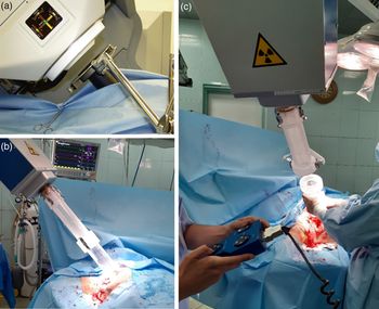
The electron beam dosimetry of portable dedicated IORT accelerators is different and more complicated than the conventional teletherapy accelerators.Reference Baghani, Aghamiri and Mahdavi3 Their main difference is the type of their electron beam collimation. The collimation of portable electron beam accelerators is performed by a hard docking and a soft docking system. IOERT commercial accelerators are equipped with cylindrical applicators. Each applicator is divided into upper and lower parts. In the hard docking system, the upper part of the applicator can be connected to the accelerator head and the lower part can be contacted to the tumour bed. But in the soft docking system, the applicator can be placed within the tumour bed and the central axis of electron beam will be adjusted along the central axis of applicator by a motion control system automatically.Reference Strigari, Soriani, Landoni, Teodoli, Bruzzaniti and Benassi11–Reference Wysocka, Adrich and Wasilewski16 Set-up of hard docking and soft docking system for two examples of real IOERT procedures are shown in Figure 1.
(a) View of the final soft docking indicator for the Intraoperative-RT Mobetron.Reference Gunderson, Willett, Calvo and Harrison2 (b) View of the hard docking indicator for the Intraoperative-RT LIAC. (c) View of the final docking indicator for the Intraoperative-RT LIAC.

In the current study, the head of LIAC (12 MeV model), as a portable dedicated IORT accelerator, equipped with hard docking applicators, was simulated using Monte Carlo Nuclear Particles (MCNP) Monte Carlo (MC) code. Radiation contamination dose (RCD) around this accelerator was calculated. The accuracy of simulation was validated by comparing its output with the ion chamber measurement data. Eventually, RCD of electrons and photons was estimated at different distances and angles around the accelerator head for all LIAC’s electron beam energies.
Two main methods exist to evaluate RCDs, measurement and MC calculation. In this work, we calculate the amount of RCDs in the different combinations of electron applicator/energy, distance and radius around the machine. There are several limitations if we want to evaluate RCDs with measurements. Firstly, it takes a long time because we repeat measurements for each one of the applicators, energies, distances and radii. Secondly, precise setting up of detector at different radius is difficult. Thirdly, the IORT machine should be on and exposes along time for being able to get all the discussed data which did not have commercial and dosimetric justification. Lastly, the radiation worker may receive a large amount of dose during measurements. However, MC methods as a gold standard have good dosimetric calculations after validation, which do not include any of the above mentioned limitations.
In additional to the above-mentioned, the impact of RCDs is highly regarded for patient skin and biological systems. A survey of skin radiation dose is particularly important. Therefore, knowing the RCDs amount is highly recommended in order to protect the patient from excessive radiation exposure because of the very high planned dose as an exclusive radiation modality (23–30 Gy), or as a boost (8–20 Gy), especially for breast carcinoma in an IOERT treatment.Reference Ciocca, Pedroli and Orecchia7–Reference Soriani, Felici and Fantini10 In additional, patients’ and operators’ radiation protection can be considered by knowing about RCDs amount around the LIAC.
Materials and Methods
LIAC dedicated IORT accelerator
LIAC dedicated IORT is one of the small and portable linear electron accelerators which can be used within the operating room and be employed for exposure immediately after surgery. LIAC accelerator is manufactured by Sordina (Sordina IORT Technologies S.p.A, Vicenza, Italy, SN 0034) and installed in a medical department for the first time in 2003.Reference Baghani, Robatjazi, Mahdavi and Hosseini Aghdam1–Reference Robatjazi, Mahdavi and Takavr4 The accelerator consists of a main control unit and is connected with a 10-m cable which can control the required high voltage, monitor units, applicator size, electron energy, expose time and turn on/off of the LIAC machine. The LIAC accelerator has two main different models: 4, 6, 8 and 10 MeV and 6, 8, 10 and 12 MeV. In this study, 12 MeV energy model is employed. LIAC dose rate can be adjusted from 5 up 30 Gy per minute using pulse repetition frequency from 1 up 60 Hz. The LIAC accelerator is equipped with several sterilisable and transparent polymethyl methacrylate (PMMA) cylindrical electron applicators and each one is 60 cm in length, 0·5 cm wall thickness and with a diameter size of 3, 4, 5, 6, 7, 8 and 10 cm (as reference) applicator. The distal end of the applicators is flat and beveled to 0, 15, 30 and 45° which are designed with PMMA plastic. This accelerator has 820 μm aluminium scattering foil and 55 μm titanium exit window. The scattering foil is used for flattening the electron beam, reducing neutron contamination and controlling photon contamination. The LIAC accelerator can easily be transported within the operating room and it is about 400 kg in weight.Reference Baghani, Aghamiri and Mahdavi5,Reference Soriani, Felici and Fantini10,Reference Beddar, Biggs and Chang14,Reference Righi, Karaj, Felici and Di Martino15
MC simulation
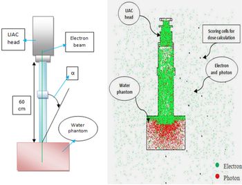
The MCNP MC code is a valid MC code in the simulation and transporting of different particles and radiation in the various geometries. In this study, the MCNP MC code was employed to simulate the head of LIAC accelerator, PMMA electron applicators, and MP3-XS water phantom. The head of LIAC consists of a titanium exit window, scattering foil and ionisation chambers with different applicator sizes that have been applied in our MC simulations. It should be mentioned that all of the data for simulation have been taken from the manufacturer (Sordina, SpA). Also, the electron source characteristics including the energy spectra at different nominal energies and intensity profile of incident electrons on exit window have been considered in the simulations.Reference Robatjazi, Mahdavi and Takavr4,Reference Soriani, Felici and Fantini10,Reference Beddar, Biggs and Chang14 The cut-off energies for electron and photon beams were considered as 0·5 and 0·01 MeV, respectively.Reference Baghani, Robatjazi, Mahdavi and Hosseini Aghdam1,Reference Soriani, Felici and Fantini10 Two- and three-dimensional views of simulated system for 10 cm reference applicator are shown in Figure 2. Size of scoring voxels was set to 0·3 × 0·25 × 0·25 cm3 to calculate the percentage depth dose (PDD) along the central axis of the electron beam inside the water phantom. Also, the same scoring voxel size was set to calculate the transverse dose profile (TDP) at the depth of maximum dose perpendicular to the central axis of beam. A 25 × 30 × 30 cm3 water phantom was considered in the simulation. But, to evaluate the RCD around the LIAC, the size of scoring voxels was considered as 0·35 × 0·3 × 0·3 cm3. A schematic of the explained geometry and its MC simulation results are shown in Figure 3. The number of followed histories in each MC simulation was equal to 109. Dose equivalent distributions around the machine are calculated in terms of mSv. For this purpose, the weighting factor of 1 was regarded for radiations of photons and electron particles. To validate the MC results, the PDD and TDP for reference applicator (10 cm diameter) at all LIAC electron beam energies were compared to those measured by the Advanced Markus ion chamber. The gamma index analysis was employed for comparing data. The gamma index calculations were performed by Gnuplot software (version 4.4 patch level 3; Geek net Inc., Fairfax, VA, USA) using its gamma index executive file.Reference Hosseini Aghdam, Baghani and Mahdavi17
Two- and three-dimensional views of the simulated system for the 10-cm reference applicator using MCNP MC simulation.

Schematic plan and MC model for the calculation of radiation contamination dose around the LIAC.

Measurement
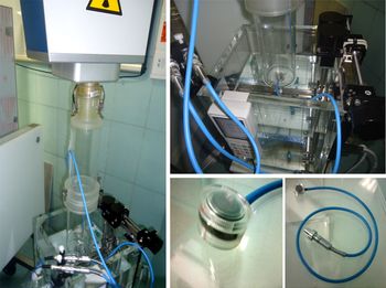
To validate the MC simulations, the PDDs along the central axis of the electron beam and TDP at the depth of maximum dose were measured in the MP3-XS water phantom (PTW, Freiburg im Breisgau, Germany) for reference applicator in all LIAC electron beam energies. An Advanced Marcus ion chamber dosimeter (PTW, Freiburg im Breisgau, Germany) was employed in experimental measurements. A digital electrometer (PTW, Freiburg im Breisgau, Germany) providing 300 V was also used on the chamber.18 GnuPlot was employed to show the difference between the experimental results of Advanced Markus and MC simulation for PDD and TDP. According to its definition, gamma index would be less than 1 if the difference between our experimental measurement and MC simulation data was less than 3%. The experimental set-ups of absorbed dose measurement inside MP3-XS water phantom using a waterproof Advanced Markus ion chamber are shown in Figure 4.
Experimental set-up view of absorbed dose measurement inside a MP3-XS water phantom using Advanced Markus ion chamber.

RCD Calculation
In the current study, the RCD has been evaluated in terms of microsievert per monitor units (µSv/MU) in all LIAC electron beam energies related to 3, 5, 7 and 10 cm circular electron applicators. According to Equations (1) and (2), we extracted a coefficient factor between the LIAC radiation dose rates and MC calculation, and then the obtained results of MC simulation are converted into µSv/MU. The measured radiation dose rates are shown in Table 3 at different combination of electron beam energy and applicator sizes. The radiation contamination dose (RC) around the LIAC accelerator can be estimated through the following equations:
 $${\rm K} = {\rm D}_{{\rm mes}}/{\rm D}_{{\rm mc}}$$
 $${\rm R}_{\rm C} = {\rm K} \times {\rm R}_{{\rm mc}}$$
where Dmes is the measured dose rate of LIAC at the depth of maximum dose inside a MP3-XS water phantom in terms of µSv/MU, Dmc is the dose rate of MC calculation at the depth of maximum dose in terms of (MeV/g) per particle, K is a coefficient factor and Rmc is the contamination dose gained from MC calculation around the LIAC in terms of (MeV/g) per particle. In general, we correlate MC results with the machine monitor unit and its results are based on µSv/MU.
Results
The PDD curves along the central axis of the LIAC electron beam for reference applicator in all LIAC electron beam energies using both MC simulation (the statistical uncertainty in all of the MC simulations was less than 3%) and measurement are shown in Figure 5, and it should be mentioned that they is no any air gap between the distal end of applicator and surface of the phantom.
Measured and Monte Carlo simulated PDDs related to the 10-cm reference applicator in all LIAC electron beam energies.

Both Experimental and MC simulation data of the TDP at the depth of maximum dose in the MP3-XS water phantom for reference applicator in all LIAC electron beam energies are shown in Figure 6.
Measured and Monte Carlo simulated TPDs related to the 10-cm reference applicator in all LIAC electron beam energies.

Figures 7 and 8 illustrate the gamma analysis results for validation of MC simulations and both PDDs and TPDs, respectively. The differences are less than 2%.
Gamma index values of PDD as a function of water depth for all LIAC electron energies.

Gamma index values of transfer dose profile as a function of water depth for all LIAC electron energies.

The mean difference error of MC simulation between scoring dose voxels for different applicator size and electron beam energies has been reported in Table 1.
Mean difference error (%) of Monte Carlo simulation between scoring cell for different applicator and electron beam energies

Table 2 reports the standard deviation of Advanced Markus electron chamber measurements at the depth of maximum dose for reference applicator and different electron beam energies.
Standard deviation (%) of Advanced Markus electron chamber measurements at the depth of maximum dose for the 10-cm diameter reference applicator and different electron beam energies

The LIAC radiation dose rates at maximum depth dose point inside a MP3-XS water phantom

In Table 3, the radiation dose rates that related to 3, 5, 7 and 10 cm electron applicator sizes in all LIAC electron beam energies at the depth of maximum dose inside a MP3-XS water phantom are reported.
The angular RCD related to electron and photon for all LIAC electron beam energies and 3, 5, 7 and 10 cm diameter electron applicator sizes in different distances and angles around the LIAC are shown in Figures 9–12. The minimum calculated contamination dose is 7·3 µSv/MU which is related to 3 cm electron applicator at 100 cm distance for 6 MeV electron beam energy. Also, the maximum calculated contamination dose is 165 µSv/MU which is related to 10 cm diameter electron applicator at 30 cm distance for 6 MeV electron energy.
Angular distribution of electron and photon radiation contamination dose for 3 cm electron applicator in all LIAC electron energies.

Angular distribution of electron and photon radiation contamination dose for 5 cm applicator in all LIAC electron energies.

Angular distribution of electron and photon radiation contamination dose for 7 cm applicator in all LIAC electron energies.

Angular distribution of electron and photon radiation contamination dose for the 10-cm reference applicator in all LIAC electron energies.

Discussion
According to PDD curves, dose gradient increases with increasing depth, up to the depth of maximum dose (Zmax), and then quickly drops. This is due to electron beam characteristics, because electron scatter and secondary electron density decrease with increasing energy and depth, respectively. According to obtained TDP curves, the symmetry of electron field in all electron beam energies is more favourable. Nevertheless, the flatness of the electron field increases with increasing electron energy. This can be explained by considering the lateral scattering of electron beams, which is less in high-energy electrons. The smaller penumbra region of the LIAC electron field is an advantage of this machine by which the surrounding healthy tissues will also receive lower doses.
Besides the electron contaminations, it is also possible for a medical linear electron accelerator to include photon contamination; the photon contamination as bremsstrahlung process is due to the electron interaction with the accelerator head, phantom and other equipments that exist on the accelerator head.
However, there may be neutron contamination when we use photon beams; however, this was not measured as part of this study. The mentioned radiations can be placed at the end of PDD curves as a bremsstrahlung tail. Nevertheless, according to the PDD curves, it was observed that the bremsstrahlung tail effect is very slight. The reason might be that the head of LIAC dedicated IORT accelerator is manufactured with low atomic number materials such as PMMA, Mylar and PEEK. Therefore, the collision of electrons with low atomic number materials can produce low radiation contamination.
According to Figures 9–12, the RCD of electron and photon beams around the machine decreases by increasing distance from accelerator head. This can also be explained by the inverse-square law and decreasing in radiation intensity by increasing distance.
The RCD behaviour at different angles relative to the central axis of electron beam is different. The amount of RCDs under the water equivalent phantom is lower than the other points, because of a large fraction of radiations which are absorbed into the 15 × 30 × 30 cm3 dimension phantom. On the other hand, the RCD decreases by increasing angles from the applicator wall in the opposite side of the electron beam direction. It is due to the decrease in effective distance between electron source position on the accelerator head and scoring voxels for dose calculation by increasing the angles to central axis of electron beam.Reference Wysocka, Adrich and Wasilewski16
Also, according to Figures 9–12, the RCD decreases with increasing the electron beam energy, because of the low probability of bremsstrahlung phenomenon for the low electron beam energies. So, the amount of RCD around the accelerator is lower in low electron energy exposure. The same result is obtained with decreasing applicator diameter size, because in the small field (small applicators) electron beam is collimated, and in consequence the output factor of machine is decreased.18
Conclusion
In this study, the radiation doses of electron and photon beams were calculated around the LIAC dedicated IORT accelerator. According to the good agreement between the results of MC simulation and experimental measurements, it can be concluded that the MCNP MC code is known as a suitable method to evaluate radiation contamination dose. Also, according to the results, maximum contamination dose happened at lower than 30° angles to the applicator walls and at the close distances around the accelerator head during exposure. However, the contamination dose from LIAC dedicated IORT accelerator is considerably lower than those produced by the conventional teletherapy machines. Therefore, the LIAC can safely be employed in a standard and conventional operative room with almost any radiation shielding or minimum shielding requirement. However, some portable shields should be used to avoid unnecessary exposure of patient and operation room personnel.
Acknowledgements
None.
Financial Support
This research received no specific grant from any funding agency, commercial or not-for-profit sectors.
Conflicts of Interest
None.