
Introduction
Studies from multiple perspectives have agreed that photosynthesis, which is an energy-harvesting process in the life of plants and certain bacteria, is understood to convert solar energy extremely efficiently, with high quantum efficiency.[Reference Ke1] While the process initiates with photo-absorption by antenna pigments and ends with the synthesis of adenosine triphosphate via multiple energy/electron transfer processes, one photon is capable of deriving one electron. The structure and alignment of the pigment-protein complex are designed to enable this highly efficient flow. The proton pump system in purple bacteria is made from light-harvesting (LH) 1, 2 complexes, a reaction center (RC), and a cytochrome bc 1 complex. The structures and the energy flow within this system have been described in the literature.[Reference Ke1] The organization of bacteriochlorophyll a (BChl a) in the complex gives the antenna pigments the capability to absorb different wavelengths. In the first step of the photosynthesis process, antenna pigments such as B800, B850 and B880 absorb solar energy. Excitation energy transfer (EET) then occurs in each pigment, from a lower energy level to a higher level, which finally excites the special pair (SP) that is located within the RC. The excitation energy is then converted into electrons in the RC.
The structures of the LH1 and LH2 complexes and the RC were revealed to have tubular or letter C shapes using x-ray crystallography for some bacteria species.[Reference Karrasch, Bullough and Ghosh2–Reference Allen, Feher, Yeates, Komiya and Rees14] Transmission electron microscopy of Rhodospirillum rubrum has revealed that the LH1 and LH2 complexes are both ring-shaped.[Reference Karrasch, Bullough and Ghosh2] The distribution of the complexes in a photosynthetic membrane was also revealed using atomic force microscopy.[Reference Sumino, Dewa, Noji, Nakano, Watanabe, Hildner, Bösch, Köhler and Nango15, Reference Yajima, Furukawa, Nagata, Sakai, Kondo, Iida, Dewa and Nango16] 3D x-ray crystallography of LH2 complex from Rhodopseudomonas acidophila 10,050 was reported in 1995.[Reference McDermott, Prince, Freer, Hawthornthwaite-Lawless, Papiz, Cogdell and Isaacs17] These studies revealed that the complexes are likely to construct domains to attain high LH efficiency.
The purpose of this study is to understand the EET flow in such a domain structure. While the former studies mentioned above are more focused on characterizing the complexes and the natural membrane using microscopies and spectroscopies, we propose a bottom-up process for patterning the complexes in artificial domain structures. This is useful for characterizing the domain structures seen in the natural membrane because the complexes can be aligned in a configuration with certain parameters and can be compared. In a previous report, we demonstrated a method to construct a stripe pattern composed of the LH2 complex on an inorganic support.[Reference McDermott, Prince, Freer, Hawthornthwaite-Lawless, Papiz, Cogdell and Isaacs17] We have been using LH1-RC and LH2 from Rhodobacter sphaeroides (Rb. sphaeroides) because of our experience with site-directed mutation of amino acids.[Reference Nagashima, Shimada, Matsuura and Nagashima18–Reference Sumino, Dewa, Sasaki, Kondo and Nango20] In this work, we report on the patterned co-immobilization of LH1-RC and LH2 on an electrode to measure the photocurrent signal from a two-complex system that has an artificial domain structure. This work is applicable to further modification of the domain structure using simple lithographic processes. The work will provide a powerful tool that will allow us to determine and experimentally understand the optimum structural parameters of the complex domain.
Materials and methods
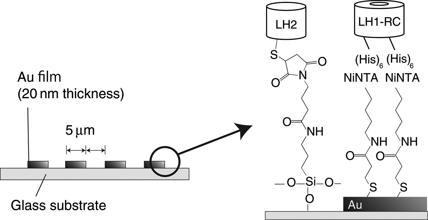
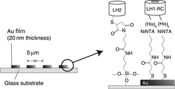
Selective immobilization of LH1-RC and LH2 was performed in three steps: (1) fabrication of a patterned support; (2) cultivation of muted bacteria and isolation of the pigment-protein complexes; and (3) surface modification of the support and immobilization of the complexes. Figure 1 shows the fabrication procedure used for the complex-immobilized substrate. The procedure began with a glass substrate with a 20-nm-thick gold layer, on which the gold layer was etched into a stripe pattern with 5 µm intervals using a lift-off process. Muted Rb. sphaeroides that contain LH2 with a thiol C-terminus (C-Cys) and LH1-RC with a His-tagged C-terminus (C-His) were cultivated and the chromatophore was fabricated.[Reference Loach, Androes, Maksim and Calvin21] Each complex was isolated from the chromatophore.[Reference Wang, Shimonaga, Kobayashi and Nozawa22] The surface of the stripe-patterned support was modified using self-assembled monolayers (SAMs) to bond each complex at a similar height. The LH2 (C-Cys) was immobilized on top of the glass stripes using 3-aminopropyltriethoxysilane and maleimide labeling. The LH1-RC (C-His) was immobilized on top of the gold using Dithiobis (C2-NTA) via APTS (3-aminopropyltriethoxysilane) and GMBS (N-(4-Maleimidobutyryloxy)succinimide).[Reference Sigal, Bandad, Barberis, Strominger and Whitesides23, Reference Noji, Bald, Yasuda, Itoh, Yoshida and Kinosita24] For comparison purposes, substrates that intentionally lacked either LH1-RC or LH2 were also prepared in addition to the co-immobilized substrate.
Schematic illustration of the co-immobilized substrate composed of LH1-RC and LH2 on a patterned surface.

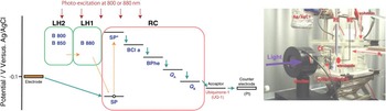
The measurements and the evaluations of the fabricated samples were performed as follows. Their absorption spectra were measured and compared before and after immobilization. This was done to ensure that the complexes are immobilized without their pigments being destroyed. In addition, fluorescence microscopic observations were conducted to check whether or not the immobilization to selective inorganic supports was successful. Finally, the photocurrent from each complex-immobilized substrate was measured. Figure 2 shows an illustration of the electron and energy flows in the custom photocurrent measurement system. The substrates were immersed in 0.1 M sodium perchlorate and 0.1 M-phosphate buffer solution (pH 7.0) that contains 5 µM ubiquinone-1. Three electrode electrochemical cell was used. Ag/AgCl reference electrode with saturated KCl, Pt conter electrode, and the complex-patterned Au electrode as the working electrode were placed in the setup. Overall surface area of the working electrode was 1 cm2. Monochromatic light irradiation system (SM-25 from Bunkoukeiki Co., Ltd, Hachioji, Japan) was used for illuminating the working electrode with a tuned wavelength. Potentiostat (HA-150 G from Hokuto Denko Corp., Meguroku, Japan) was used for electrochemical measurement. The substrates were illuminated at either 880 or 800 nm while the current was monitored. The illumination was modulated at intervals of 30 s to eliminate the effects of floor noise. Illumination at 880 nm excited B880 in LH1 directly, which was followed by SP excitation. Illumination at 800 nm was intended to excite B880 in LH2, where the pigment has the lowest energy level in the two-complex system. In this case, indirect EET flow via B850 and B880 for SP excitation is expected.
Illustrations of the photocurrent measurement setup. (Left) Excitation energy and electron flows within the measurement system. (Right) Photograph of the instrumental setup. In the left diagram, the divisions in green and pink separate the parts of the pigment-protein complexes, i.e., LH2, LH1, and RC. The green solid line and the orange and red broken lines represent the flows of the electrons, the excitation energy, and the photoexcitation energy, respectively. RE, WE, and CE in the photograph on the right represent the reference, working and counter electrodes, respectively.

Results and discussion
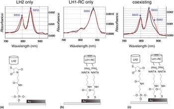
The absorption spectra of the complex-immobilized substrates are shown in Fig. 3. Figures 3(a) and 3(b) show the cases in which single complexes are used. The dual peaks seen in (a) and the single peak seen in (b) represent the pigments B800, B850, and B880, which are present in each complex.[Reference Frese, Olsen, Branvall, Westerhuis, Hunter and van Grondelle9] Waveforms that were obtained from the solution and for the substrate are represented by the red and black lines in the figure, respectively. The fact that these waveforms are matched fairly well in both (a) and (b) indicates that the pigments were not deformed or destroyed by the immobilization procedure. Part (c) represents the co-immobilized system. The broadening of the B850 peak towards the red direction is caused by the B880 that is present in LH1. This broadening behavior is seen to differ slightly between solutions and substrates in that the second peak in (c) shows the difference between the black and red traces. This is believed to represent the difference between the alignments of the complexes. LH1-RC and LH2 are dissolved randomly within the solution, whereas they were aligned in stripe patterns on the substrate. That difference will cause differences in the distances between the complexes and in the number of contacts that cause EET.
Absorption spectra of complex-immobilized substrates (red lines) and complex-dissolved PL buffer solutions (black lines). (a)–(c) represent the spectra obtained from LH2 alone, LH1-RC alone, and co-existing LH2 and LH1-RC, respectively.

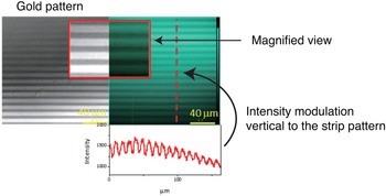
Figure 4 shows the fluorescence microscopy view of the LH2-only substrate. The selective immobilization of LH2 on top of the glass was confirmed by matching of their locations on the glass with the parts that emit fluorescence. Of the two complexes that were used in this study, LH2 is the only complex that emits fluorescence alone. If the LH2 is adjacent to an LH1-RC, EET from B850 to B880 will quench the fluorescence. Therefore, it also proves that LH1-RC is not present on the glass surface. Fluorescence cannot be obtained from the LH1-RC because it holds the SP that converts the excited energy into an electron. The micrograph shows the bonding used for LH2 immobilization on the glass substrate.
Fluorescence microscopy image of LH2 (C-Cys) assembled on 5 µm-patterned etched substrate with C2-NTA and APTS and GMBS.

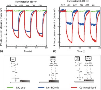
Figure 5 shows the photocurrent responses that were measured from the illuminated substrates. (a) and (b) show the responses obtained for excitations at 880 and 800 nm, respectively. The signal amplitude from the co-immobilized substrate exceeds the corresponding amplitude from the LH1-RC-only-substrate in both (a) and (b). In particular, (b) shows a more pronounced improvement as a result of the use of the co-immobilized structure. These facts indicate that the adjacent structures of the two complexes are capable of improving the LH efficiency. The results also indicate that EET was likely to occur as the natural photosynthetic membrane was demonstrated using an artificially-arranged pattern of complexes. Obviously, no currents were generated by the LH2-only substrates because they lack the RC required to generate the electrons.
Photocurrent characteristics of complex-assembled substrates. (a) and (b) show the responses obtained at illumination wavelengths of 880 and 800 nm, respectively. Green, blue, and red traces represent the currents obtained from the LH2-immobilized substrate, the LH1-RC-immobilized substrate, and the co-immobilized substrate containing LH2 and LH1-RC. In all cases, the illumination was modulated on and off at 30 s intervals.

Conclusions
LH2 and LH1-RC pigment-protein complexes that have been separated from Rb. sphaeroides were aligned on a plane in a stripe pattern at 5 µm intervals. Observation of the absorption spectra and fluorescence microphotographs indicated the selective immobilization and conservation of these pigments. The largest photocurrent signal was obtained using the co-immobilized substrate under excitation at a wavelength of 800 nm. This result demonstrated that the native structure with the adjacent structure composed of the two complexes is suitable for efficient LH activity while using limited materials species. It also indicated that re-alignment and immobilization of the complexes on an electrode occurred to enable evaluation of the EET and the photocurrent. The results of this work can be applied to optimization of the distribution and the ratio of two complexes using supports with various stripe intervals or other patterns.
Acknowledgments
The authors thank Masaharu Kondo, Shunsuke Yajima, Kaori Harada, Kenji V. P. Nagashima, Kouji Iida, and Takehisa Dewa for experimental supports. This work was partially supported by JST/CREST, by a Grant-in-Aid for Scientific Research from the Ministry of Education, Culture, Sports, Science and Technology (MEXT), Japan, and by AOARD. The authors also thank David MacDonald, MSc, from Edanz Group (www.edanzediting.com/ac) for editing a draft of this manuscript.