1. Introduction
The copper vapour laser (CVL) is one of the efficient sources of coherent light in the visible region at 510.6 and 578.2 nm with high average power. CVLs have wide applications in research, medicine and industry. Moreover, they are considered to be a powerful pumping source for dye lasers (Withford et al.
Reference Withford, Brown, Mildren, Carman, Marshall and Piper2004), particularly by means of a master oscillator-power amplifier array, in order to satisfy higher output powers and beam quality simultaneously (Behrouzinia, Sadighi & Parvin Reference Behrouzinia, Sadighi and Parvin2003; Aghababaei Nezhad et al.
Reference Aghababaei Nezhad, Sajad, Behrouzinia, Salehinia and Khorasani2010). The plasma temperature and electron density are most important parameters that affect the operation of gas lasers such as CVLs. Under a local thermodynamic equilibrium (LTE) condition in the plasma, the excitation temperature governing the distribution of energy level excitation through the Boltzmann equation and the ionization temperature governing the ionization equilibrium through the Saha equation, are equal to the electronic temperature describing the Maxwellian distribution of electron velocities (Bakshi & Nunnally Reference Bakshi and Nunnally1995; Griem Reference Griem1997; Gupta & Sari Reference Gupta and Sari2010 for more details). Thus, a plasma in LTE has a common temperature
 $T$
, called the plasma temperature. The most widely used spectroscopy method for the determination of
 $T$
is the Boltzmann plot method (Griem Reference Griem1997), which employs the ratio of integrated line intensities for two or more laser lines. Based on the two-dimensional heat conduction equation solved under boundary conditions of the third and fourth kind, a new approach is proposed for determining the gas temperature in the cross-section of a copper bromide laser (Lilycho, Snezhana & Sabotinov Reference Lilycho, Snezhana and Sabotinov2009). Temperature profiles in the cases of natural and forced convection are obtained, taking into account the basic laser parameters such as the laser design, the input electric power, etc. In particular, computer simulations for the case of forced convection are performed in order to increase the input electric power at a fixed maximum discharge temperature (Lilycho et al.
Reference Lilycho, Snezhana and Sabotinov2009).
In this work, we report the measurement of plasma temperature
 $T$
and the temperature profile in a CVL plasma. Moreover, we used three kinds of mirrors in the CVL resonator cavity, one commercial mirror (dielectric coated) and two homemade mirrors of copper coated on BK7 substrate and copper bulk as the back mirror. The temperature profiles have been obtained for each mirror individually and compared with each other.
2. Experimental apparatus
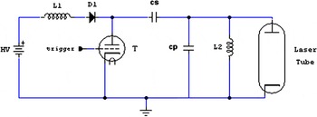
The discharge tube of the CVL is made of alumina with an inner diameter of 16 mm and an active medium length of 60 cm, surrounded by a fibrous alumina insulation covering with a Pyrex tube and an external stainless steel jacket. Two molybdenum cylindrical electrodes are employed for discharging. A couple of flat–flat resonators with reflectivities of 98 % and 4 % are usually considered for the back and front mirrors, respectively. The laser tube is coupled to the standard driven circuit, as illustrated in figure 1. The gas in the tube is excited by the discharge of a 1.65 nF storage capacitor
 $(C_{s})$
through a TGI1-
 $1000/25$
Thyratron which is cooled with air. A 0.68 nF peaking capacitor
 $(C_{p})$
is connected between the tube electrodes as well as a 0.15 mH inductance (L2). Under conditions of 25 Torr with He as the buffer gas, an electric input power of 1.7 kW and frequency of 20 kHz, a maximum output power of 4.5 W is obtained.
The laser output is measured by a
 $\text{Molectron}^{\text{TM}}$
PM500D power meter. A diaphragm with four holes, one slit and a spectral filter for separating the green and yellow lines have been used in this experiment. A spectrometer Model Carry500 is used for measuring the reflectivity of mirrors.
Schematic layout of standard driven circuit of the CVL.

3. Result and discussion
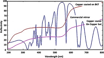
In this work, three kinds of mirrors, one commercial mirror (dielectric coated) and two homemade mirrors of copper coated on BK7 substrate and copper bulk have been used as the back mirror individually, and the output powers are measured versus pulse repetition frequency under same conditions, i.e. He gas pressure of 25 Torr and electric input power of 1.7 kW. The layers of Cr (150 nm), Cu (300 nm) and MgF2 (100 nm) are deposited on BK7 substrate by physical vapour deposition. The reflectivity of the mirrors is obtained with UV/VIS spectroscopy versus wavelength (200–800 nm) as demonstrated in figure 2.
The reflectivity of mirrors versus wavelength.

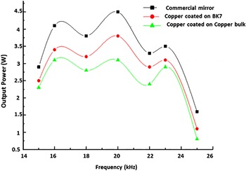
The output power of the laser has been measured versus frequency with different back mirrors used individually, as illustrated in figure 3.
The output power of the CVL versus frequency with different back mirrors.

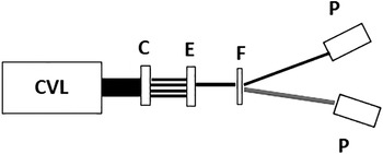
The notable point is that the oscillatory behaviour of the output power in terms of frequency is in agreement with our previous reports (Khorasani et al. Reference Khorasani, Salehinia, Behrouzinia, Sajad and Parvizian2008; Zoghi et al. Reference Zoghi, Parvin, Behrouzinia, Salehinia, Khorasani and Mehravaran2009). This effect arises from the laser tube, which performs both as an optical and an acoustic resonator at some frequencies. It is shown that the maxima and minima of output powers for all mirrors occurred at the same frequencies. The output power of the laser with a dielectric coated mirror is higher than that of the metallic coated mirrors, and the output power with the copper coated on BK7 substrate mirror is higher than that of flat copper bulk mirror. This is related to the reflectivity coefficients of the mirrors (see figure 2). The schematic diagram of the experimental set-up for determination of the temperature profile is presented in figure 4. The circular copper diaphragm (C) has four holes. The first hole is located in the centre of the diaphragm, and the subsequent holes have distances of 2 mm from each other along the radius of the diaphragm. The radius of each hole is 1 mm. The central hole is adjusted in front of the tube axes and the last one is aligned near the tube wall. A single slit (E) permits the passing of one of the beams and by adjusting the slit, one beam can be selected. The selected output beam is split into green and yellow lines through a spectral filter (F), and the output powers of each beam are simultaneously measured by power meters (P).
Experimental set-up for determination of the temperature profile of the CVL.

In a plasma with temperature
 $T$
, a spectral line corresponding to a transition from energy level
 $l$
to energy level
 $m$
has intensity,
 $I_{l_{m}}$
, as given by (3.1). (Lochte-Holtgreven Reference Lochte-Holtgreven1968)
 $$\begin{eqnarray}I_{l_{m}}=\frac{A_{l_{m}}g_{l}}{U}h{\it\nu}_{l_{m}}n\exp (-E_{l}/{\it\kappa}T).\end{eqnarray}$$
In this equation,
 $A_{l_{m}}$
is the transition probability,
 $g_{l}$
is the degeneracy of the upper level,
 $U$
is the internal partition function for the emitting species,
 ${\it\nu}_{l_{m}}$
is the frequency of the emitted radiation,
 $n$
is the density of the emitting species and
 $E_{l}$
is the energy of the upper level.
Provided that the plasma frequency is less than the laser frequency, the plasma is optically thin. Also, in pulsed CVLs, the value of electron density is of the order of
 ${\sim}10^{13}~\text{cm}^{-3}$
. After glow discharge, the plasma tends to an equilibrium condition (Kushner & Warner Reference Kushner and Warner1983), therefore LTE is approximately satisfied.
The less rigorous method of temperature measurement (less rigorous in the sense that a Boltzmann distribution is assumed from the start) is to use the ratio of emission intensities of the transitions in the same emitting species. This ratio is shown in (3.2). (Muraoka & Maeda Reference Muraoka and Maeda2001)
 $$\begin{eqnarray}\frac{I_{lm}}{I_{\acute{l} \acute{m}}}=\frac{A_{lm}g_{l}{\it\lambda}_{\acute{l} \acute{m}}}{A_{\acute{l} \acute{m}}g_{\acute{l} }{\it\lambda}_{lm}}\exp \left(-\frac{E_{l}-E_{\acute{l} }}{{\it\kappa}T}\right),\end{eqnarray}$$
where
 $I_{l_{m}}$
and
 $I_{\acute{l} \acute{m}}$
are intensities,
 ${\it\lambda}_{\acute{l} \acute{m}}$
and
 ${\it\lambda}_{l_{m}}$
are wavelengths,
 $g_{l}$
and
 $g_{\acute{l} }$
are degeneracy degrees,
 $A_{l_{m}}$
and
 $A_{\acute{l} \acute{m}}$
are transition probabilities and
 $E_{l}$
and
 $E_{\acute{l} }$
are upper level energies of the green and yellow lines, respectively.
 ${\it\kappa}$
is the Boltzmann constant and
 $T$
is the plasma temperature. Because the upper levels of both transitions of CVL are close to each other, the temperature effect of the Boltzmann factor on the reproducibility of the line intensity ratio is minimized and, at the same time, consideration of the efficiency factor of the collecting system is avoided (Gupta & Sari Reference Gupta and Sari2010). The values of those parameters for two line transitions of a CVL are arranged in table 1 and are used in this work. By measuring the output intensities and inserting these data in (3.2), the temperature is obtained. The plasma temperature obtained by this method (
 ${\sim}1550\,^{\circ }\text{C}$
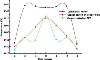
) is in agreement with the operational optimized temperature of a CVL. The temperature profiles of the CVL with different mirrors are presented in figure 5. It is shown that the temperature profile of the laser using the dielectric coated mirror is more uniform along the cross-section of tube than those of the metallic coated ones. Therefore, the output power of the laser with the dielectric coated back mirror is more than those of the metallic coated ones.
Temperature profiles of the CVL.

Wavelengths, lower and upper energy levels, upper level degeneracy and transition probability of the CVL emission lines (Gupta & Sari Reference Gupta and Sari2010).

4. Conclusion
Although the reflectivities of mirrors with various coating are different, the use of a copper coated one as a back mirror in the resonator cavity has a good output in the CVL. The fabrication of this mirror is easier than that of the dielectric coated one and also has a longer lifetime and is easier to clean. The temperature profile of the laser using the dielectric coated mirror is more uniform along the cross-section of the tube than those of the metallic coated ones. Thus the output power of the laser with the dielectric coated back mirror is greater than those of the metallic coated ones. Therefore, to increase the output power of gas lasers such as the CVL, the temperature profile should be made to be as uniform as possible along the cross-section of the laser tube.