Introduction
The fundamental mechanism of shape change, or plasticity, in crystalline metals is the generation, motion, and interaction of dislocations.Reference Hirth and Lothe1 A major triumph of classical crystal plasticity theories is that they predict the mechanical properties of metals based directly on the density of dislocations,  ${\rm{\rho }}$, in the material.Reference Roters, Eisenlohr, Hantcherli, Tjahjanto, Bieler and Raabe2 One key assumption of these theories, however, is that the dimensions of the body undergoing deformation are much larger than the characteristic spacing between dislocations, which may be estimated as
 ${{\rm{\rho }}^{ - 1/2}}$. Thus, taking
 $2 \bullet {10^7} - 3 \bullet {10^{11}}$ cm/cm3 as the representative range of dislocation densities encountered in well-annealed to heavily cold-worked metals,Reference Williamson and Smallman3 we expect classical crystal plasticity theories to break down for domain sizes below ∼0.2–2 μm.
One example of this breakdown is size-dependent mechanical properties, sometimes referred to as the “smaller is stronger” effect,Reference Maass, Van Petegem, Ma, Zimmermann, Grolimund, Roters, Van Swygenhoven and Raabe4 observed in particles, wires, and sheets with submicron dimensions.Reference Greer and De Hosson5 Another is the elevation in yield and flow strength of polycrystalline metals that occurs as grain sizes are reduced to ∼100 nm and below.Reference Meyers, Mishra and Benson6 In both examples, the dimensions of crystalline domains are so small compared to the characteristic spacing between dislocations, that the frequency of dislocation interactions with free surfaces or solid-state interfaces (i.e., grain and phase boundariesReference Sutton and Balluffi7) equals or exceeds the frequency of dislocation interactions with each other. Thus, the properties of surfaces and interfaces, especially the way they interact with dislocations,Reference Beyerlein, Demkowicz, Misra and Uberuaga8 are of prime importance for understanding and predicting the mechanical behavior of submicron scale (i.e., nanoscale) metallic objects or aggregates thereof.
The paramount importance of surfaces and interfaces for plasticity within nanoscale domains motivates a reevaluation of the role of domain shape in plastic deformation. In continuum crystal plasticity theories, where domain dimensions are substantially larger than the spacing between dislocations, the mechanical properties at any point in the material are determined solely by the local dislocation density. While domain shapes may affect solutions to boundary value problems,Reference Lebensohn, Brenner, Castelnau and Rollett9 they have no influence on the constitutive relations governing the mechanical response of individual representative volume elements. Is that still the case at the nanoscale? The shape of nanoscale domains determines the type and arrangement of surfaces and interfaces bounding them (i.e., their area, orientation, curvature, connectivity, and crystallographic character). These, in turn, affect the degree of dislocation confinement along different slip planes and directions. Are the plastic strains (i.e., shape changes) induced by dislocation motion indifferent to these parameters or does shape affect shape change at the nanoscale?
An unambiguous demonstration that shape does indeed matter for plasticity at the nanoscale may be obtained by considering examples of materials with extreme differences in microstructural morphology, such as single-component nanocrystalline metals and nanolaminate composites made of phase-separating metals. When processed by powder compaction, the former contain nearly equiaxed grains that offer the same level of confinement to dislocation motion in all directions.Reference Ma10 Thus, in the absence of texture, these materials may be modeled as plastically isotropic solids.Reference Wei and Anand11,Reference Fu, Benson and Meyers12
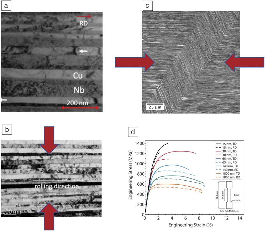
In contrast, nanolaminate composites, whose constituent grains have aspect ratios of ∼30 or higher,Reference Carpenter, Vogel, LeDonne, Hammon, Beyerlein and Mara13 exhibit distinct plastic anisotropy, as illustrated in Figure 1.Reference Zheng, Beyerlein, Carpenter, Kang, Wang, Han and Mara14 For example, compression of nanolayered composites of copper (Cu) and niobium (Nb) along the axis perpendicular to the layers results in uniform thinning of the layers.Reference Carpenter, Vogel, LeDonne, Hammon, Beyerlein and Mara13 Meanwhile, compression along an axis parallel to the layers activates deformation via layer kinking.Reference Nizolek, Begley, McCabe, Avallone, Mara, Beyerlein and Pollock15 Flow stresses in this material are also highly anisotropic.Reference Nizolek, Beyerlein, Mara, Avallone and Pollock16
(a) The Cu/Nb nanolaminate composite shown (b) thins uniformly when compressed perpendicular to the layers, but (c) undergoes kinking when compressed parallel to the layers. Red arrows in (b, c) indicate compression directions. The load-bearing capacity of the composite is highly anisotropic, (d) as illustrated by the tensile stress–strain curves. Note: RD, loading in the rolling direction; TD, loading in the transverse direction. (a) Reprinted with permission from Reference Reference Carpenter, Vogel, LeDonne, Hammon, Beyerlein and Mara13. © 2012 Elsevier. (b) Reprinted with permission from Reference Reference Beyerlein, Mayeur, Zheng, Mara, Wang and Misra52. © 2014 National Academy of Sciences. (c) Reprinted with permission from Reference Reference Nizolek, Begley, McCabe, Avallone, Mara, Beyerlein and Pollock15. © 2017 Elsevier. (d) Reprinted with permission from Reference Reference Nizolek, Beyerlein, Mara, Avallone and Pollock16. © 2016 AIP Publishing.

Notably, these plastic deformation behaviors are a direct outcome of the anisotropic shape of the nanoscale grains and cannot be explained if the layers are modeled as bulk-scale solids using continuum crystal plasticity theory alone.Reference Hansen, Carpenter, Sintay, Bronkhorst, McCabe, Mayeur, Mourad, Beyerlein, Mara, Chen and Gray17 In particular, the nanoscale thickness of the layers constricts the length of dislocation segments on glide planes that intersect the layer interfaces while leaving their mobility parallel to layer interfaces relatively free. The net outcome of these constraints is confined layer slip:Reference Misra, Hirth and Hoagland18 a dislocation-based plasticity mechanism that gives rise to hardening and consequently flow uniformity for uniaxial compression perpendicular to the layers.Reference Akasheh, Zbib, Hirth, Hoagland and Misra19 By contrast, activation of kink banding requires dislocation glide along slip planes oriented parallel to the layers: a geometry that does not constrict the length or mobility of dislocation segments as severely as confined layer slip and results in lower hardening rates.
Metal nanocomposites, such as the previously mentioned nanolaminates, are excellent model materials for investigating the effect of the shape of nanoscale crystal domains on mechanical properties. In addition to laminates, such composites have been made in the form of nanoscale particlesReference Chee, Stumphy, Vo, Averback and Bellon20 or ligamentsReference Thilly, Veron, Ludwig, Lecouturier, Peyrade and Askenazy21 embedded in a continuous matrix. However, recent interest in nanocomposite design has shifted to materials with more intricate, often hierarchical microstructural morphologies. A recent report gives examples of several such materials across a wide range of application areas,Reference De Yoreo22 with hierarchical metal nanocomposites, in particular, expected to play an especially important role in advanced nuclear energy technologies.Reference Beierschmitt23
The remainder of this article presents two types of metal nanocomposites well-suited to the investigation of complex microstructural morphologies and their effects on mechanical behavior—those formed by phase separation in physical vapor codeposited (PVcD) alloys and those synthesized by liquid-metal dealloying (LMD). Both composite types give rise to a wide range of microstructure morphologies as compositions and processing conditions are varied. Early mechanical testing and computer simulation studies on these materials are also presented. Finally, challenges and opportunities for future research are discussed.
Phase-separated PVcD materials
Metastable solid solutions of low-solubility element pairs, such as Cu-Nb,Reference Banerjee, Puthucode, Bose and Ayyub24 Cu-W,Reference Vullers and Spolenak25 or Cu-Mo,Reference Derby, Cui, Baldwin and Misra26 may be synthesized by PVcD. When deposited at room temperature, these alloys often take on a noncrystalline (amorphous) structure. Even in the absence of crystallization, subnanometer patterning into compositionally enriched domains is observed in these materials.Reference Banerjee, Puthucode, Bose and Ayyub24,Reference Baumer and Demkowicz27 Upon annealing, these amorphous alloys undergo simultaneous crystallization and phase separation via the formation and growth of spherulitic domains consisting of near-equilibrium crystalline phases embedded in a metastable amorphous solid solution.Reference Puthucode, Devaraj, Nag, Bose, Ayyub, Kaufman and Banerjee28 The two constituent phases in these domains take on complex, interconnected shapes, resulting in the formation of a morphologically complex composite upon complete devitrification.
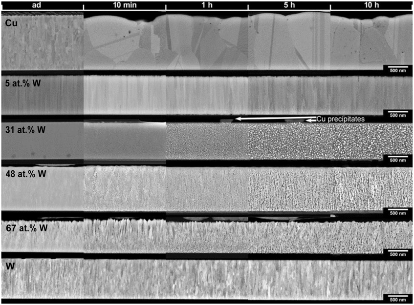
Vüllers and Spolenak conducted a comprehensive investigation of the phase-separated morphologies of room-temperature codeposited Cu-W films after annealing at 750°C.Reference Vullers and Spolenak25 They investigated a wide range of film compositions, from 5 to 67 at.% W, and annealing times from 10 min to 10 h. Figure 2 illustrates the range of microstructure morphologies they observed in cross sections obtained by ion-beam milling. For films with W content beneath 48 at.%, annealing leads to the formation and coarsening of numerous, discrete, W-rich particles embedded in a Cu matrix. For W content between 48 and 67 at.%, this situation reverses, giving rise to Cu-rich precipitates embedded in a W-rich matrix. The W-rich films exhibit a pronounced columnar structure, giving rise to an anisotropic morphology with elongated Cu-rich domains oriented perpendicular to the sample surface.
Montage of cross-sectional views of Cu-W films of varying composition codeposited at room temperature and subsequently annealed over a range of times at 750°C. Arrows indicate the Cu-rich capping layer in the 31 at.% W sample. Note: ad, as-deposited. Reprinted with permission from Reference Reference Vullers and Spolenak25. © 2015 Elsevier.

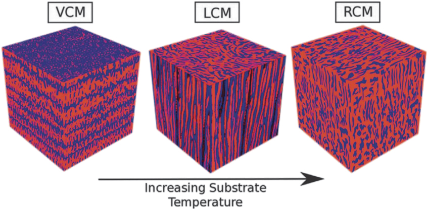
Derby et al. investigated the microstructural morphology and mechanical response of PVcD Cu-Mo films and obtained results that contrasted with the previous finding.Reference Derby, Cui, Baldwin and Misra26 Rather than anneal samples that had been deposited at room temperature, they performed codeposition at elevated temperatures between 400°C and 800°C and deposition rates between 0.12 and 1.4 nm/s. Their investigation was confined to a single composition with 45 at.% Cu. By examining microstructural morphology both along sample surfaces and cross sections, they identified three distinct morphology types, as shown in Figure 3—vertical composition modulations (VCMs), lateral composition modulations (LCMs), and random composition modulations (RCMs).
Three canonical morphology types observed in Cu-Mo films codeposited at elevated temperatures: vertical composition modulations (VCMs), lateral composition modulations (LCMs), and random composition modulations (RCMs). Reprinted with permission from Reference Reference Derby, Cui, Baldwin and Misra26. © 2018 Elsevier.
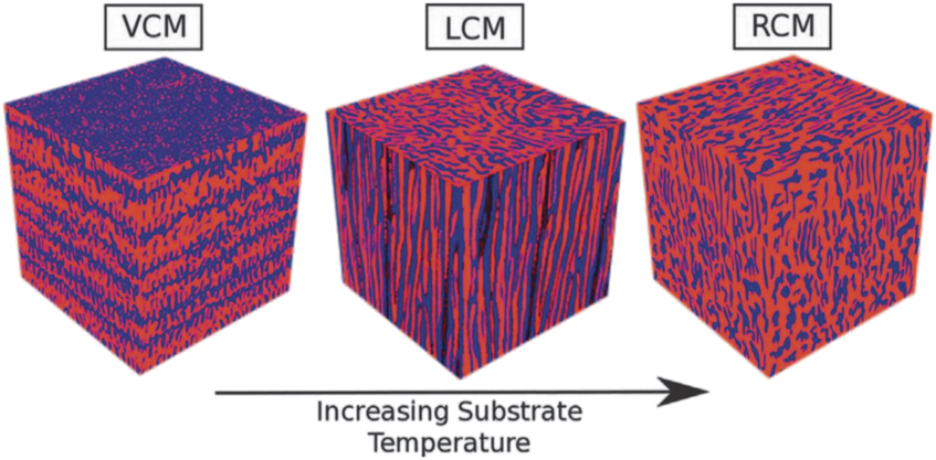
The primary factor that determines the type of morphology that forms during PVcD of Cu-Mo is the deposition temperature, with the lowest temperature giving rise to VCMs and the highest temperature yielding RCMs. These observations agree with the findings of Lu et al., who carried out two-dimensional phase field simulations of morphology evolution in phase separating PVcD alloys.Reference Lu, Wang, Gao, Shi, Liu and Wang29 They demonstrated the emergence of VCM and LCM morphologies, the former at lower and the latter at higher temperatures. Their simulations did not observe the RCM morphology because it is inherently a three-dimensional (3D) structure and therefore could not be captured by their model. Interestingly, Adams et al. report the opposite trend in PVcD Al-Ge films, with VCMs occurring at higher temperatures than LCMs.Reference Cui, Derby, Li, Mara and Misra30 In the experiments of Derby et al., the effect of deposition rate appears to be limited to determining the characteristic dimensions of the compositionally enriched domains, with the lowest rates giving rise to ∼100-nm-sized features and the highest yielding ∼10-nm-scale features.Reference Derby, Cui, Baldwin and Misra26 This trend agrees with the Monte Carlo simulations of Adams et al.Reference McCue, Karma and Erlebacher31
Lu et al. furthermore found that VCMs appear to emerge by a local rearrangement in the immediate vicinity of the sample surface, suggesting that this morphology requires high-temperature deposition and cannot form during post-deposition annealing. Indeed, there is no sign of VCMs in the Cu-W films in Figure 2. Meanwhile, the cross-sectional views of LCMs shown in Figure 3 appear comparable to the W-rich columnar composite structures shown in Figure 2, suggesting that the latter might also exhibit a LCM morphology. However, the formation of a Cu-rich capping layer on all the Cu-W films discussed in Reference Reference Vullers and Spolenak25 prevented the acquisition of plan-view surface micrographs, precluding definitive conclusions concerning the 3D morphology of these films. It remains to be determined whether the range of morphologies shown in Figure 3 is only accessible via high-temperature deposition or if they also arise in post-deposition annealing. Vüllers and Spolenak conducted annealing at only one temperature, so it is not clear whether other morphologies may emerge at other annealing temperatures in Cu-W.
Vüllers and Spolenak used nanoindentation to investigate the modulus and hardness of their Cu-W films.Reference Vullers and Spolenak25 For all annealing times, both quantities exhibited the same monotonic variation with composition, in reasonable agreement with the rule of mixtures. It appears that the differences in microstructure morphology exhibited by these materials do not have a discernible effect on indentation modulus or hardness. Cui et al. performed indentation and nanopillar compression testsReference Cui, Derby, Li, Mara and Misra30 on PVcD Cu-Mo materials synthesized by Derby et al.Reference Derby, Cui, Baldwin and Misra26 and compared them to the mechanical response of nanolaminate composites synthesized by alternating deposition of pure Cu and pure Mo. They found that both the PVcD materials and the multilayers had comparable hardness and flow strength under compression, confirming that microstructure morphology does not have any clear effect on the strength of these materials.
Cui et al., however, found a clear difference in the approach to steady-state flow exhibited by multilayers and PVcD films. The former displayed an extended elastic range followed by a rapid transition—spanning 1–2% plastic strain—to nearly perfect-plastic flow. Moreover, the multilayer exhibited localization of flow into sharp shear bands, leading to early and sudden failure of the microcompression specimen. In contrast, the PVcD material showed a prolonged transition to steady-state flow spanning nearly 10% plastic strain. Departure from linear elastic behavior occurred at substantially lower stress than in the multilayered specimen and was followed by extensive hardening behavior. The PVcD microcompression specimen exhibited a greater degree of uniform plastic deformation than the multilayered specimen, without formation of shear bands and without sudden failure. These results suggest that while microstructural morphology may not have a pronounced effect on the ultimate strength of the nanocomposite, it has a marked influence on the hardening behavior and consequently on the uniformity of plastic flow. In particular, the complex, intertwined morphologies of PVcD materials appear to be more resistant to flow localization than the multilayer nanocomposites.
LMD composites
In dealloying, one component of an initially uniform parent alloy is dissolved away into a surrounding solvent while the remaining component self-organizes into a morphologically complex microstructure. For example, nanoporous metals made by dealloying in aqueous solvents have garnered great interest over the past two decades,Reference McCue, Karma and Erlebacher31,Reference McCue, Benn, Gaskey, Erlebacher and Clarke32 with nanoporous gold being the most extensively investigated.Reference Erlebacher, Aziz, Karma, Dimitrov and Sieradzki33,Reference McCue, Stuckner, Murayama and Demkowicz34 More recently, it has been shown that dealloying can also be carried out using liquid metalsReference Wada, Yubuta, Inoue and Kato35,Reference Wada and Kato36 or even solid metalsReference Wada, Yubuta and Kato37,Reference McCue and Demkowicz38 as solvents. Unlike dealloying in aqueous media, LMD and solid metal dealloying may be used not only to synthesize porous materials,Reference Yu, Yubuta, Wada and Kato39–Reference Okulov, Weissmuller and Markmann43 but also fully dense, multiphase metal composites.Reference McCue and Demkowicz38,Reference Geslin, McCue, Gaskey, Erlebacher and Karma44,Reference McCue, Gaskey, Geslin, Karma and Erlebacher45
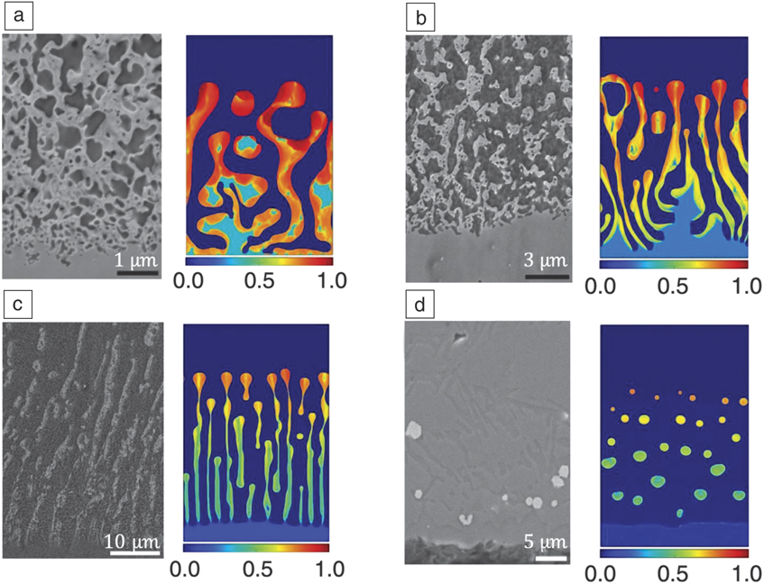
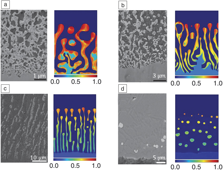
One distinct advantage of composite synthesis via LMD is the wide range of composite morphologies that can be produced. For example, Geslin et al. investigated composites made by dealloying TaxTi1–x parent alloys in liquid Cu.Reference Geslin, McCue, Gaskey, Erlebacher and Karma44 As illustrated in Figure 4, by changing the parent alloy composition, they observed a wide range of morphologies, from particles in a matrix (Figure 4d), to lamellar (Figure 4c), to interpenetrating bicontinuous (Figure 4a–b). The authors also demonstrated a similar range of morphologies in concurrent phase-field simulations of the dealloying process. By changing the dealloying time and temperature, the characteristic dimensions of these composite structures may be altered.Reference McCue, Gaskey, Geslin, Karma and Erlebacher45 Moreover, because LMD composites can be fabricated in bulk form, they are amenable to post-processing treatments, such as cold rolling.Reference Mokhtari, Le Bourlot, Adrien, Dancette, Wada, Duchet-Rumeau, Kato and Maire46
Micrographs and corresponding phase-field models of metal composites made by dealloying of TaxTi1–x alloys in liquid Cu: (a) x = 0.35, (b) x = 0.25, (c) x = 0.15, (d) x = 0.05. The color map in the phase-field models shows the concentration of the parent alloy component that is immiscible with the solvent. Reprinted with permission from Reference Reference Geslin, McCue, Gaskey, Erlebacher and Karma44. © 2015 Nature Publishing Group.
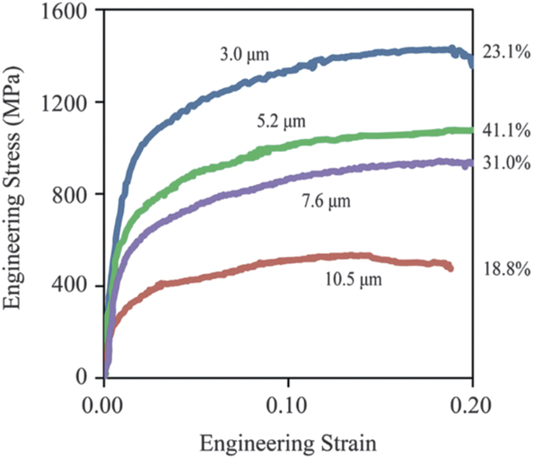
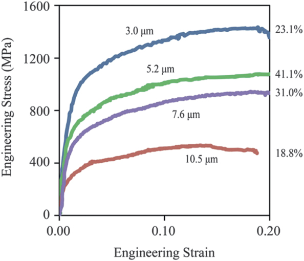
McCue et al. used nanoindentationReference McCue, Gaskey, Crawford and Erlebacher47 as well as uniaxial compression and tension testingReference McCue, Ryan, Hemker, Xu, Li, Chen and Erlebacher48 to characterize the mechanical properties of LMD composites. As expected, these materials exhibited marked differences in local indentation modulus and hardness, depending on which phase in the composite was being indented.Reference McCue, Gaskey, Crawford and Erlebacher47 Uniaxial compression tests on larger-scale specimens showed a clear dependence of strength on the characteristic dimensions of the domains making up the composite, with smaller features yielding stronger materials, as demonstrated by the stress–strain curves in Figure 5. Since domain dimensions were on the micron level in all of the composites tested, this variation was interpreted as being analogous to the classical Hall–Petch effect in single-phase polycrystals. Interestingly, concurrent with the increase in strength with decreasing microstructure dimensions, these materials also exhibited increasing rates of strain hardening. It remains to be determined whether these trends persist as component dimensions decrease to the submicron and nanometer level.
Stress–strain curves for uniaxial compression of composites made by dealloying of TaxTi1–x alloys in liquid Cu. All curves are labeled by the characteristic dimensions of the composite constituents. The strains to failure for each test are given on the right side of the figure. Reprinted with permission from Reference Reference McCue, Ryan, Hemker, Xu, Li, Chen and Erlebacher48. © 2016 Wiley.
Challenges and opportunities
While phase-separated PVcD and LMD composites both provide new opportunities for studying the effects of microstructure morphology on plastic flow behavior, investigations of these materials are still in the early stages with questions greatly outnumbering answers. In particular, in both cases, complete descriptions of microstructural morphology are rarely possible because detailed 3D reconstructions of the microstructure morphology are often lacking. Depending on characteristic microstructure dimensions, different approaches to obtaining such reconstructions may be pursued. Banerjee et al. showed that atom probe tomography is suitable for investigating phase distributions in PVcD composites with nanometer-scale dimensions.Reference Banerjee, Puthucode, Bose and Ayyub24,Reference Puthucode, Devaraj, Nag, Bose, Ayyub, Kaufman and Banerjee28 On the micrometer scale, Zhao was able to use x-ray nanotomography reconstructions to reconstruct 3D microstructure morphology.Reference Zhao, Wada, De Andrade, Williams, Gelb, Li, Thieme, Kato and Chen-Wiegart42 Once acquired, 3D reconstructions may be analyzed to quantify the topology, connectivity, and interface curvatures of the composite morphology.Reference Chen, Chu, Yi, McNulty, Shen, Voorhees and Dunand49,Reference Mendoza, Thornton, Savin and Voorhees50
Mechanical testing of these materials is also at an early stage, yet a variety of techniques has already been applied to them, including nanoindentation,Reference Vullers and Spolenak25,Reference Cui, Derby, Li, Mara and Misra30,Reference McCue, Gaskey, Crawford and Erlebacher47 micropillar compression,Reference Cui, Derby, Li, Mara and Misra30 and conventional uniaxial loading.Reference McCue, Ryan, Hemker, Xu, Li, Chen and Erlebacher48 One area of potential future opportunity is to combine small-scale mechanical testing with nondestructive morphology reconstruction via x-ray nanotomography.Reference Zhao, Wada, De Andrade, Williams, Gelb, Li, Thieme, Kato and Chen-Wiegart42 Comparisons of microstructure morphologies before and after deformation may provide insights into the mechanisms responsible for the deformation behavior of these materials, especially their apparent high hardening rates. Due to the low frequency of dislocation–dislocation interactions in nanocomposite solids, explaining the high rates of hardening seen in these materials may require the postulation of novel, nondislocation-based mechanisms. Improved tracking of microstructure evolution during deformation may shed light on these mechanisms.
Finally, dedicated atomistic simulations are needed to understand the mechanisms responsible for the deformation behavior of phase-separated PVcD and LMD composites. Atomic-scale models may be constructed using experimentally acquired 3D microstructure reconstructions. Alternatively, they may also be created using phase-field simulations as a template, in analogy to the approach commonly used in the modeling of nanoporous solids.Reference Beets and Farkas51 With improved understanding of the connections between microstructural morphology and mechanical deformation, new types of designer morphologies optimized for peak mechanical performance may be designed and synthesized, hastening the transition of morphology-controlled metal composites from the lab to technological use.
Acknowledgment
This work was supported by the National Science Foundation DMREF Program under Grant No. 1623051.

Michael J. Demkowicz is an associate professor in the Department of Materials Science and Engineering at Texas A&M University. His research focuses on the role of solid-state interfaces (grain and phase boundaries) in the performance of metals in extremes. This research has impacted industry by elucidating intergranular failure mechanisms and advanced the US Department of Energy’s national energy security mission by spearheading the development of interface-dominated radiation-resistant composites. He currently serves as the director of the Center for Research Excellence on Dynamically Deformed Solids (CREDDS), an National Nuclear Security Administration–supported center of excellence. Demkowicz can be reached by email at demkowicz@tamu.edu.