Introduction
The demands of dual and multiband filters are always high as they reduce the number of filters, circuit size, and cost of a system. Along with the band selection, switchable passbands, wide stopbands, harmonics suppression are some of the important characteristics of bandpass filters (BPFs) [Reference Sun, Wang and Li1, Reference Chaudhary, Jeong and Lim2]. In paper [Reference Sun, Wang and Li1], the p-i-n diode switching offers single, dual, and triple passbands, whereas [Reference Chaudhary, Jeong and Lim2] presents tunable dual-band BPF with harmonic suppression up to 10f 2, where f 2 is the center frequency of the second band. Though the design of paper [Reference Chaudhary, Jeong and Lim2] offers excellent harmonic suppression, varactor diodes limit the operational power level up to 12 dBm. Design of dual-band filters are more convenient with planar stepped impedance resonators (SIRs) as it offers excellent control on the tuning of frequency ratios [Reference Makimoto and Yamashita3, Reference Zhu and Abbosh4]. Though SIRs offer best frequency tuning, they are lossy. On the other hand, substrate integrated waveguide (SIW) offers lower loss and higher power handling [Reference Deslandes and Wu5]. Dual and triple-band SIW filters are reported in paper [Reference Chen, Wu and Li6], whereas paper [Reference Shen, Wang, Kang and Wu7] presents a dual-band differential BPF with improved common mode suppression. A SIW dual-band filter in paper [Reference Xie, Zhou, Zhou and Wu8] offers wide stopband, but harmonic suppression is not achieved. Dual-band filters using hybrid structures of microstrip and SIW reported in papers [Reference Wu, Mao, Yin and Guo9, Reference Zhu and Dong10] offer good out-of-band rejections but do not offer any harmonic suppression. The dual-band SIW filters loaded with complementary split ring resonators (CSRR) reported in papers [Reference Yin and Lin11–Reference Hammed13] offers good isolation between the two passbands but not useful for harmonic suppression. The design reported in paper [Reference Zheng, Tan, Li and Chen12] uses half mode SIW loaded with CSRR, offers two TZs in between the two passbands but spurious responses at any harmonics are not being discussed. Similar response without any harmonic suppression can be found in paper [Reference Hammed13]. In paper [Reference Li, Luo, Chen, Liu, Xu and Chen14], SIW-based dual-/tri-/quad-band BPFs are reported using via loaded perturbed cavities. Due to the lower order of the filters, out-of-band rejections are limited and no harmonic suppression properties are shown. The design of dual-band SIW filter using independent coupling of TE101 and TE102 modes proposed in paper [Reference Chu, Luo, Zhou, Guo, Zhu, Zhang, Liu and Wu15] do not offer any harmonic suppression characteristic.
Though the filters with wide stopbands are very popular in radio frequency (RF) design, BPFs with harmonic suppression capabilities are also important especially for the use at the output of a nonlinear circuit. To create a wide stopband requires higher filter order and complex topologies which in effect increases the filter size as well as the passband insertion loss. The design becomes more challenging for a dual or multiband design. Therefore, design of a compact BPF with good regular harmonic suppression is an important aspect for specific applications.
Here, a third-order dual-band BPF is presented using SIW and microstrip SIRs that effectively suppresses regular harmonics of both the passbands at least up to fourth order. If an input signal with angular frequency of ω is fed to a nonlinear network, the output contains frequency components at 2 ω, 3 ω, 4 ω, and so on [Reference Razavi16]. For most of the RF applications, generation of harmonics up to 3 ω due to the nonlinearity is most significant. Generation of such high-frequency components do not only increase the interferences but also reduces the efficiency. Therefore, harmonic suppression network at the output of a nonlinear network is very essential. Here, the filter is designed for such applications with the capability of suppressing the regular harmonics of f 1 = 2.4 GHz ISM and f 2 = 3.5 GHz 5 G bands at least up to 5f 1 and 4f 2. The two passbands are created by the fundamental and next higher order resonances of both types of resonators, whereas the frequency mismatches of other higher order resonances are utilized to suppress the regular harmonics. The proposed geometrical layout makes the filter compact. This regular harmonic suppression characteristic makes the proposed filter suitable for the application as a harmonic suppressing network of a dual-band nonlinear circuit.
Design and analysis
The SIW and microstrip SIRs
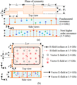
Figure 1 shows the microstrip SIR and rectangular SIW resonator (SIWR) along with the field sketches at their fundamental and next higher order resonances at the design frequencies of f 1 = 2.4 GHz and f 2 = 3.5 GHz, respectively. At f 1 and f 2, the SIR acts as a half and full wavelength open ended resonator, respectively, whereas the SIWR resonates in TE110 and TE210 modes. The frequency ratio (f 2/f 1) for the SIR is obtained by adjusting L 1, L 2, W 1, and W 2 [Reference Makimoto and Yamashita3], and for the SIWR it is tuned by W SIW/L SIW as described in paper [Reference Khan and Mandal17].
Sketches of (a) vector E-field in microstrip SIR and (b) vector E-field and H-field isolines in the rectangular SIW resonator (SIWR).

For all the simulations, Rogers’s RO4003C substrate of thickness (h) = 0.813 mm with εr = 3.38, tan δ = 0.0027 and ®Ansoft’s HFSS simulator are used.
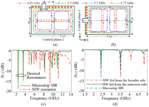
Figure 1(b) shows that the metallic vias of diameter d = 1.0 mm and pitch p = 2.0 mm are placed at the side of microstrip feeding as their positions can be adjusted to obtain required external Q-factor (Q e). Other side walls of the SIWR are electroplated in the final design. For the desired f 2/f 1, the initial dimensions are L 1 = 19.6 mm, W 1 = 5.1 mm, L 2 = 13.8 mm, W 2 = 0.9 mm, L SIW = 54.2 mm, W SIW = 43.2 mm. Microstrip edge coupling and inset feeding are used to excite SIR and SIWR, respectively. The feeding shown in Fig. 2(a) results unwanted resonances at 4.05 and 4.8 GHz along with the desired f 1 and f 2. The unwanted TE120 mode at 4.05 GHz degrades the out-of-band rejection of the second passband while the arbitrary resonance at 4.8 GHz is at 2f 2. The feeding orientation shown in Fig. 2(b) results first unwanted resonance in TE310 mode at 4.75 GHz as the existence of E-field maxima on the feeding plane does not excite TE120 mode. The sketches of H-field isolines for the first three resonances for both the feedings are also shown in the figures. Figure 2(c) shows the |S11| plots. As the feeding shown in Fig. 2(b) suppresses TE120, it is finalized for rest of the design. With this feeding L SIW = 54.2 mm and W SIW = 43.2 mm for desired f 1 and f 2. Other dimensions of the SIWR are unchanged.
Feeding across (a) broader and (b) narrower side of the SIW resonator, (c) |S11| with feeding orientations, and (d) |S11| of microstrip SIR and SIWR.

On the other hand, as Fig. 1(a) shows, the microstrip edge coupling is used to excite the microstrip SIR. Starting from the formula given in paper [Reference Makimoto and Yamashita3], optimized dimensions of the SIR are L 1 = 19.8 mm, W 1 = 4.2 mm, L 2 = 13.6 mm, W 2 = 0.9 mm for desired f 1 and f 2. Simulated |S11| of the SIR is also shown in Fig. 2(c).
From the wideband frequency characteristics of SIR and SIWR shown in Fig. 2(d), it can be observed that the SIR offers unwanted resonances at 5.2, 8.0, 9.9, and 11.05 GHz, whereas the SIWR offers as many as 14 unwanted resonances. The excitation of TEmn0 modes with arbitrary field distributions inside the SIWR results a greater number of unwanted resonances. From the plots of Fig. 2(d), it can be observed that except near 8.0 and 9.9 GHz, all other unwanted resonances supported by the SIR and SIWR are non-overlapping and the higher order resonances of SIR are not at mf 1 and nf 2 at least up to m = n = 4, where m and n are integers.
The filter structure and its working
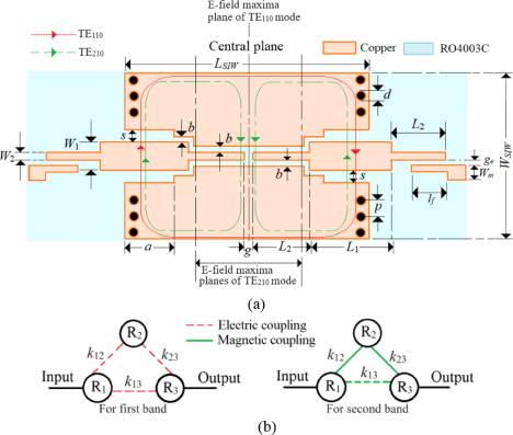
In the proposed third-order filter shown in Fig. 3(a), R1 and R3 are the SIRs, whereas R2 is the SIWR. The gap b between the SIRs and SIW top plane controls the direct couplings k 12 and k 23 between R1-R2 and R2-R3 for both the bands. The gap g controls the bypass coupling k 13 between R1 and R3. The input and output are 50 Ω microstrip lines of width Wm = 1.81 mm. The trisection topology of the filter is shown in Fig. 3(b).
(a) Proposed filter structure and (b) coupling topologies.

In this design, two out of three resonators are microstrip SIRs as it offers lesser number of unwanted resonances at least up to 4f 2 and the remaining one the rectangular SIWR. The energy coupling from the 50 Ω feedline depends on g e and l f, hence external Q-factor (Q e). Therefore, increasing g e results higher Q e, whereas longer l f lowers Q e and vice versa. Figure 2(d) shows that the common resonances supported by the SIR and SIWR are at 8.0 and 9.9 GHz. As the SIWR does not support resonances at 5.2 and 11.05 GHz, these SIR resonances are rejected by SIWR R2. Therefore, along with the f 1 and f 2, signals only at 8.0 and 9.9 GHz reach the output with considerable strength but they are not regular harmonics of f 1 and f 2.
Studies of main (k12, k23) and bypass (k13) couplings
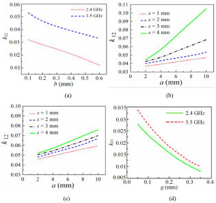
The main couplings k 12 and k 23 depend on a, b, and s. Increasing b increases the gap between SIR and SIW hence k 12 and k 23 decrease and vice versa but due to the different field distributions, their values and variations are not identical at f 1 and f 2. As the field sketches of Fig. 1 and filter structure of Fig. 3(a) suggest a complete half wavelength for SIWR and more than half wavelength field variation for SIR exist within L SIW/2, the effective k 12 at f 2 is always higher than at f 1. The variation of k 12 with b is shown in Fig. 4(a). Due to the symmetry, k 12 = k 23.
Variation of coupling k 12 (a) only with b. Variation of k 12 with a for different s at (b) f 1 = 2.4 GHz, (c) and f 2 = 3.5 GHz. (d) Variation of k 13 with g.

Next, step a with separation s between SIR and SIW top plane is introduced. The s increases the separation between SIW top plane and side edges of the SIR which improves its quasi-TEM excitation resulting better mode matching with the TE modes of SIWR. Therefore, increasing s and a increases k 12 and k 23, which can be observed in the plots of Fig. 4(b) and (c). For these studies, b and g are kept fixed at 0.2 mm to avoid any fabrication difficulties. The effects of a and s are different on k 12 at f 1 and f 2 due to their different field distributions.
Bypass coupling k 13 depends only on g, shown in Fig. 3(a). Increasing g increases the distance between the two SIRs, hence reduces k 13 for both the modes. Figure 4(d) reflects the same.
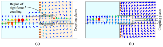
Next, the nature of k 12 and k 13 are studied. Simulated magnetic fields at lower order coupled modes for both the resonances are shown in Fig. 5 which show that the electric and magnetic walls exist on the coupling planes for fundamental and next higher order mode, respectively. Therefore, k 12 is electric in nature at the fundamental whereas it is magnetic for next resonant mode [Reference Hong and Lancaster18]. Figure 1(a) shows that E-field maxima exist at both the ends of SIR for both the resonant modes whereas minima and maxima exist on mid the plane at f 1 and f 2, respectively. As shown in Fig. 1(b), for SIWR, E-field maxima and minima exist on the plane at L SIW/2 at f 1 and f 2 respectively. Therefore, k 12 is mainly contributed by the energy coupling between SIR and SIW at the second resonant mode through the region marked in Fig. 5(b) as the region of significant coupling, whereas for the first mode, k 12 is contributed by the entire region of SIR inserted inside the SIWR due to proper field matching.
Simulated vector magnetic field plots at lower order coupled modes (a) at 2.38 GHz for first resonance and (b) at 3.45 GHz for second resonance.

On the other hand, k 13 is due to the energy coupling between the two SIRs through their end regions where E-field maxima exist for both the modes. As this energy coupling is due to the E-field fringing, k 13 is electric in nature for both the modes [Reference Hong and Lancaster18].
Tuning of bandwidths
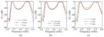
The controllability of the bandwidths is shown in Fig. 6. As the parameters a, b, and s control the direct couplings significantly, the bandwidth can be easily tuned by adjusted these parameters. Figure 6(a) shows that the bandwidth of second passband strongly depends of a for small value of s = 2 mm. Changing a from 8 to 12 mm changes the fractional bandwidth (FBW) of the second passband by 3.8%, whereas the change in FBW of the first passband is negligible. Increasing a increases the nearby metal free region of the microstrip SIR which improves the excitation of quasi-TEM mode resulting better mode matching with TE mode of SIW. As nearly one half of the E-field variation exists for TE210 mode throughout out the region where the SIR is inserted inside the SIWR, effect of a on k 12 is more prominent for the second band for small values of s. For larger s, the effect of a is prominent on k 12 for the TE110 mode as it can be observed in the coupling plots of Fig. 4(b).
Variation of bandwidth of the passbands with (a) a, (b) b, and (c) s.

On the other hand, the parameter b influences bandwidths of both the passbands. From the filter structure shown in Fig. 3(a), it can be observed that b is extended nearly from the E-field maxima position of TE210 to the center of the structure which is the position of E-field maxima of TE110 mode. Therefore, change in b changes the direct couplings k 12 and k 23 for both the bands. Increasing b results improvement in the excitation of quasi-TEM modes of the microstrip SIRs for both the modes resulting higher coupling. From the plots of Fig. 6(b), it can be observed that the bandwidths of both the passbands increase with increasing b keeping other dimensions fixed. The FBW of both the passbands increases nearly up to 2.2% as the b increases from 0.2 to 0.4 mm.
Figure 6(c) shows the variation of bandwidths of the proposed filter with s. For small values of a, increasing s significantly increases the FBW of the first passband, whereas the change in bandwidth of the second passband is negligible. The plots of Fig. 6(c) suggest that the FBW of the first band increases nearly 3.5% due to the change in s from 2.0 to 5.0 mm. It can be observed that the change in bandwidth of the second passband is negligible due to the change of s over the mentioned range.
Therefore, by adjusting a, b, and s, bandwidth of both the passbands can be tuned independently.
The final design
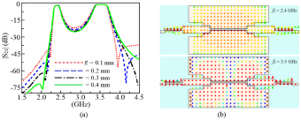
Finally, a dual-band BPF with passbands centered at 2.4 and 3.5 GHz with 3 dB FBW of 5% and 7.5%, respectively, has been designed using trisection topology. The FBWs are so chosen that the variation of |S21| remains within 1 dB over 2.35–2.45 and 3.4–3.6 GHz. The in and out of phase k 13 at first and second resonant modes result transmission zeros TZ1 and TZ2 at lower and higher stopbands of the first and second passband, respectively [Reference Razavi16]. To obtain sharp rejection TZ1 and TZ2 are placed at 2.2 and 4.1 GHz, respectively. The calculated couplings and Q e values are k 12 = k 23 = −0.055, k 13 = −0.021, Q e1 = Q e3 = 12.9 for first band and k 12 = k 23 = 0.081, k 13 = −0.053, Q e1 = Q e3 = 9.2 for the second band [Reference Hong and Lancaster18]. The electric coupling is represented with a negative sign. Figure 7(a) shows the variation of the TZs positions with g. Lower values of g increases k 13 shifting the TZs toward the passbands. The optimum dimensions are L SIW = 58 mm, W SIW = 42 mm, L 1 = 19.8 mm, L 2 = 13.6 mm, W 1 = 5.1 mm, W 2 = 0.9 mm, a = 10.2 mm, b = 0.3 mm, s = 2.8 mm, g = 0.2 mm, g e = 0.2 mm, l f = 10.8 mm, w m = 1.81 mm, d = 1.0 mm, p = 2.0 mm.
Simulated (a) |S21| with g and (b) vector E-field plots at f 1 and f 2.

Based on the previous studies, following design steps are suggested for this dual-band BPF.
• Tune W SIW/L SIW of the SIWR and W 1, W 2, L 1, L 2 of the SIR for desired f 1 and f 2.
• Select the proper feeding orientation of SIWR.
• Adjust a, b, s, and g for desired coupling values and tune l f and g e for the required external Q-factors.
As the two SIRs are inserted on the top plane of the SIW maintaining the coupling gap throughout the structure, it is important to observe the effect of this geometry on unloaded Q-factor (Q u) of the SIWR and its two modes used for the creation of two passbands. As the etched-out area on the top plane is near about 6% of overall top surface area of the SIWR, no significant changes in the field distributions of TE110 and TE210 modes being observed. Simulated vector E-field distributions shown in Fig. 7(b) confirms the TE110 and TE210 modes at f 1 and f 2 respectively. To study the loss, Q u of the SIWR is determined without and with the coupling gaps following the method described in paper [Reference Kwok and Liang19]. The Q u drops from 395 and 410 in TE110 and TE210 modes to 375 and 382, respectively, after inclusion of the coupling gaps. This drop of nearly 6.8% in Q u suggests insignificant effect of the coupling gaps on the overall loss of the SIWR.
Fabrication and measurement
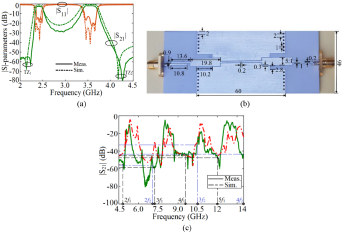
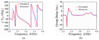
The filter is fabricated using the same 0.813-mm thick RO4003C substrate. The responses of the filter along with the photograph of the fabricated prototype are shown in Fig. 8. Figure 5(a) shows that the two passbands are centered at 2.42 and 3.55 GHz with a measured 3 dB FBW of 4.5% and 6.8%, respectively. In the measurement, the average insertion losses are 2.72 and 2.08 dB over the spans of 2.36–2.48 and 3.44–3.65 GHz, whereas the return losses are better than 14.5 and 14 dB, respectively. Figure 8(b) shows that the photograph of the prototype of the filter with optimized dimensions. Figure 8(c) shows that the BPF effectively suppresses the regular harmonics at least up to 5f 1 and 4f 2 with a minimum suppression of 30 dB at 3f 2. The TZs are positioned at 2.25 and 4.25 GHz offering rejections of 40 dB at (f 1–0.14) GHz and (f 2 + 0.35) GHz, respectively. Figure 9(a) and (b) shows the measured phase and group delay responses of the filter. The comparison in Table 1 shows that the proposed filter offers best regular harmonic suppression compared to other reported designs.
(a) Simulated and measured responses of the filter with the (b) photograph the prototype showing the optimized dimensions and (c) stopband response showing harmonic suppression.

Measured and simulated (a) phase and (b) group delay responses of the filter.

Comparison with other reported works

Conclusion
The design of a dual-band BPF with regular harmonic suppression has been presented using the combination of SIW and microstrip SIRs. The created mismatches in the higher order resonances of these two types of resonators is utilized to effectively suppress the regular harmonics at least up to 5f 1 and 4f 2. Over the entire stopband, the suppression is not high but centered about the regular harmonics, the design offers suppression better than 30 dB. The achieved minimum bandwidth of 30 dB suppression is 1.8% about the harmonic frequency of 3f 2 = 10.5 GHz, whereas at other regular harmonics, the suppression bandwidth as well as levels are much higher. The BPF effectively suppresses the regular harmonics at least up to 5f 1 and 4f 2. As the design is focused to effectively suppress the regular harmonics maintaining a compact circuit size, the rejection level between the two passbands is limited to 28 dB, which is moderate. This rejection level can further be improved with increasing the order and use of other cross coupling topologies in the expense of layout area and insertion loss. Rejections at two other sides of the passbands are not compromised. By controlling the strength of the bypass coupling using g, two TZs are placed at the passband edges. The two TZs result the rejections of 40 dB at (f 1 − 0.14) GHz and (f 2 + 0.32) GHz, respectively. Along with the harmonic suppression, significant size reduction has been achieved with the combination of SIWR and microstrip SIRs. The third-order BPF is realized within the area of 1.6λ g × 0.6λ g where λ g is the guided wavelength of SIW at 3.5 GHz. Such compact size with regular harmonic suppression capability makes this filter suitable to suppress the harmonics generated by a dual-band nonlinear network.
Competing interests
The authors report no conflict of interest.

Ajay Gupta was born in Madhya Pradesh, India. He received his M.Tech degree in Microwave and Communication Engineering from the PDPM Indian Institute of Information Technology, Design & Manufacturing Jabalpur, India, in 2019. He is currently pursuing PhD from Indian Institute of Technology Jodhpur, India. His current research interests include RF and microwave passive components like filters, antennas, diplexers, etc.

Dr. Arani Ali Khan works as Assistant Professor at Indian Institute of Technology, Jodhpur, India. He completed his PhD from Indian Institute of Technology Kharagpur, India, in 2018.His research interest includes RF and microwave active and passive components. He formerly worked in MTRDC, DRDO as research associate and RF engineer in Amphenol omni-connect.