I. INTRODUCTION
Recent developments in automobile sectors illustrate an inclination towards weight reduction of accessories and components leading to increased fuel efficiency. Reference Morishita, Kado, Abe, Sakamoto and Yoshida1 Tailor welded blanks (TWBs) have found their due share in construction of truck frames, floor panels, car side panels, wheel arches, door inner, car doors, and bumper. Reference Mohrbacher, Spottl and Paegle2 Many car manufacturers such as GM, VW, Ford, Toyota, and Fiat have used TWBs in their automobile body parts. Reference Qi3 TWBs are typically semifinished that comprise at least two single sheets that are welded together prior to the forming process. Reference Merklein, Johannes, Lechner and Kuppert4 Panda et al. investigated the properties of laser welded steel samples for various thicknesses with surface characterization techniques. Reference Panda, Kumar, Kumar and Nath5 The outcome of their research emphasized that the formability of the different thickness sheets was affected by limiting dome height and strain distribution. Safdarian et al. reported the influence of thickness ratio (TR) on the formability of TWBs. Reference Korouyeh, Naeini, Torkamany and Liaghat6 It was understood that formability and the strength of the TWB were decreased by increasing the TR. Veera et al. presented their research outcome in terms of the tensile, deep drawing, and forming behavior for base metal and the welded steel and aluminum sheet. Reference Babu, Narayanan and Kumar7 Based on the results, an expert system was developed for predicting the tensile behavior of TWB. Piwnik et al. studied the formability of weldment after microjet cooling that yielded good plastic behavior. Reference Piwnik, Hadrys and Skorulski8 Tajally and Emadoddin reported that strain hardening exponent (n) increased with annealing temperature indicating a proportionality. Hence, the ductility of the metal was improved by the annealing conditions. Reference Tajally and Emadoddin9 Winowiecka et al. reported that increasing the holding-down force reduces the risk of wrinkling of the sheets. Reference Winowiecka, Wieckowski and Zawadzki10 Anand et al. studied the fatigue strength laser welded TWB sheets. It was clear that stress concentration on thinner section was severe leading to the failure in the thinner section. Reference Anand, Chen, Bhole, Andreychuck and Boudreau11 Davies et al. observed that the selection of the welding process played a significant role in their formability behavior. Reference Davies, Oliver, Smith and Grant12 Suresh et al. studied that formability cup drawn height was more for tungsten arc welding (TIG) welded specimens. Reference Suresh, Regalla, Gupta and Padmanabham13 Kleiner et al. reported the issues arising in the lightweight metal fabrications and forming operations. The structures fabricated by aluminum, magnesium and high-strength steel were pictured and discussed. Reference Kleiner, Geiger and Klaus14 Further, it was identified that titanium and stainless steel applications were increasing in TWB production by replacing carbon steel applications based on the factors like size, safety, and durability. Reference Patel, Shah and Shah15 Adamus and Lacki reported that laser beam welding (LBW) and electron beam welding (EBW) processes were commonly adopted for titanium fabrication towards the point of eliminating contaminations in the weldments. Reference Adamus and Lacki16 Titanium being a hard multifunctional material emerges to the most suitable alternative meeting the challenges. Xu et al. reported the various type of light amplification by stimulated emission of radiation (LASER) instrument used for the production of TWBs. Reference Xu, Westerbaan, Nayak, Chen, Goodwin and Zhou17 Another examination conducted by Pallett and Lark suggested that laser welding process has limited their higher productions cost. Reference Pallett and Lark18 gas tungsten arc welding (GTAW) process provides a suitable provision for alteration owing to its techno-economical aspects. Reference Giridharan and Murugan19 Based on a thorough understanding of the literature, it is inferred that a very limited amount of research works are carried out by the past researchers in the area of development of gas tungsten arc (GTA) welded blanks of titanium material. Hence, an attempt is made to employ the automated GTAW process for joining 1.6 mm with 2 mm thin sheet in butt joint configuration. Effect of heat input, macro- and microstructures are obtained for a thorough metallurgical analysis. Subsequently, the effect of TR and welding process was probed by subjecting the specimens to mechanical testing that includes tensile and Erichsen cupping test. The fractured surfaces were examined to determine the mode of failure.
II. MATERIALS AND METHODS
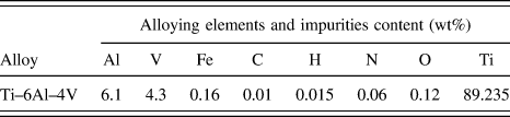
Materials used are rolled sheets of 1.6 and 2 mm thick Ti–6Al–4V alloy. The chemical composition of the parent material is presented in Table I. Square butt joint configuration is prepared to fabricate the joints using GTAW process. Prior to the joint fabrication, parameters are optimized by conducting bead-on-plate trials. Initially, few welding trials are carried out on 2 mm thick sheets of the Ti–6Al–4V alloy to determine the optimized range of parameters that yields full penetration.
Chemical composition of Ti–6Al–4V alloy.

The details of the selected optimized GTAW process parameters are listed in Table II. Necessary shielding arrangements and care taken to avoid contaminations and distortion during welding are ensured. The welded joint specimens for testing are machined with wire-cut electric discharge machine and subsequently, macro, micro, tensile, and cupping test samples are prepared. Tensile test is carried out using 50 kN load cell universal testing machine (UTM) with the strain rate of 1 mm/min (make: Tinius Olsen 50 kN, Horsham, Pennsylvania). Transverse type of tensile test sample is prepared under ASTM standards (E8M-04). Erichsen cupping test was conducted by 100 kN load cell with a punch travel speed of 10 mm/min. The test samples are prepared according to ASTM E643-84.
Optimized GTAW process parameters for welding Ti–6Al–4V alloy.

The macro- and microstructure of the sectioned portion were visualized post the polishing and etching process. Firstly, the samples are polished with different grades of emery papers. After polishing, these samples are etched with Kroll's reagent (92%H2O + 6%HNO3 + 2%HF). The macroimages were captured with the weld expert instrument (20× to 240× struers). The micrographs are captured by the optical microscope. Further the microstructure present at fusion zone (FZ) is picturized by high resolution transmission electron microscopy (HRTEM; JEM 2100, JEOL Ltd., Peabody, Massachusetts). The microhardness survey is done across the weld centerline by Vickers microhardness tester (Tukon 1102, Buehler, Shanghai, China) with 500 g load and 10 s dwell time. The fractured surface of tensile and cupping test samples is analyzed through scanning electron microscope (SEM) equipment (Hitachi S3000N, Hitachi Limited, Tokyo, Japan).
III. RESULT AND DISCUSSION
TWBs for 1.6 and 2 mm thick Ti–6Al–4V alloy sheets are butt jointed. With suitable arrangement and necessary precautions, defect free and less distortion joints are achieved. Microstructural changes and local microhardness survey are taken to study the effect of GTAW process. Due to the thickness variations, the weld line is slightly deviated. Because of this reason, FZ and heat affected zone (HAZ) are minimum in thin sheet (1.6 mm) side. Moreover tensile and cupping tests are conducted in base metal as well as the TWB. Results are summarized and discussed in the following section to understand the effect of GTAW process.
A. Weld bead appearance and macrostructure
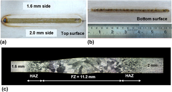
Butt joint configuration of TWB made with 1.25 TR is presented in Fig. 1. Face and root are protected against the atmosphere contaminations with specially designed fixture. Reference Kleiner, Geiger and Klaus14
Surface image of TWB (a) face side (b) root side and (c) macrograph of butt joint cross-section.

The workpiece is clamped perfectly by using welding fixture to eliminate mis-matching and deformation caused by GTAW process. With this arrangement tolerable amount of distortion is noticed in the butt joints. Uniform bead is obtained on face and root side of the joint. The weld surfaces are clean and stable throughout the entire length with remarkable weld quality. Figures 1(a) and 1(b) show the top and bottom portion of the butt joint. This image clearly shows that there are no cracks and porosity on the weld bead. The existence of defects like porosity and voids present in the TWB significantly affects the mechanical properties. Reference Davies, Oliver, Smith and Grant12 There is no undercut in the joints due to the selection of appropriate heat input (198 kJ/mm). During initial condition, slight colorization is produced. This colorization is attributed to the absence or lack of preflow of shielding medium at the arc-initiating position. Reference Karpagaraj, Siva Shanmugam and Sankaranarayanasamy20 The cross-section of macrograph clearly indicates the FZ and HAZ of the TWB. The FZ width of 11.20 mm is produced by the GTAW process. From the macrograph [Fig. 1(c)] it is clear that the width of the FZ and HAZ in the 1.6 mm thickness side is smaller than that in the 2 mm thickness portion. Compared to 2 mm side the width of the HAZ in 1.6 mm side is 21.4% less.
B. Microstructural characterization
During GTAW process, the joint portion experiences complex weld thermal cycles. This produces a spatial and temporal distribution of temperature. This results in the production of nonuniform microstructure in weld joints.
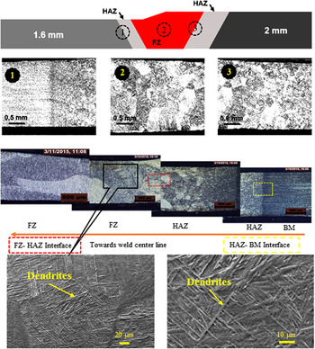
The micrographs clearly reveal that evaluation of microstructures is greatly affected by the heat input. In α + β titanium alloy, base metal contains equiaxed α + β structure. At the FZ, grain coarsening is high and size of the grains is larger than that of HAZ and BM. The boundary from the HAZ–BM interface represents the initiation of grain coarsening due to the temperature distribution. At the FZ, a highly distinct microstructure is observed.
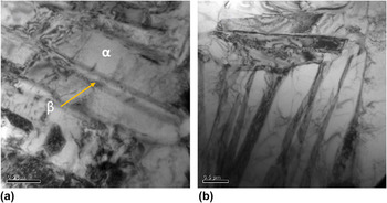
The presence of widmanstatten α-phases is identified within the transformed β grains due to the phase transformations. Based on the β-transition temperature, HAZ of the weldment may be divided into two regions namely near HAZ and far HAZ. These portions are marked and shown in Fig. 2. The peak temperature at far HAZ is lower than the β transformation temperature and is placed near to the starting point of HAZ and base metal interface. Near HAZ ranges from the β-transformation temperature to the liquids temperature and it is located adjacent to the origin of FZ. Mechanical properties of the titanium materials strongly depended on the microstructures formed at the joint portion. The evaluation of this microstructure depends on the type of welding processes on their cooling rate. Balasubramanian et al. reported that fine grains were developed in the FZ produced by high energy density processes like LBW and EBW processes due to their faster cooling rate, Reference Balasubramanian, Balasubramanian and Muthumanikkam21 whereas, coarse grains were formed in the FZ of GTA welded specimens. This was because of the higher heat input and slow cooling rate associated with the GTAW process. To visualize the microstructure present at the FZ of GTA welded blanks, transmission electron microscopy (TEM) is utilized and the images are depicted in Fig. 3. These images illustrated that thin white α-grains are surrounded by black β-grain boundaries. Same identifications were absorbed by Sundarsean et al. in pulsed GTAW in Ti–6Al–4V alloy weldments. Reference Sundaresan, Ram and Reddy22 The distribution of α-plates is such that the plates are parallel to each other [Fig. 3(a)]. These α + β grains have formed the dislocation of the weldment. The predominance of the dislocations of the grains is identified in Fig. 3(b). This type of fault occurs due to the invariant strain accompanied by the birth of ά-formations at the FZ. These dislocations have the high stacking fault energy (SFC). Meanwhile, it is very hard to break down the SFC of titanium.
Microstructure of the weldment pointing towards base metal to FZ.

TEM photographs of Ti–6Al–4V FZ at various locations (a) α-colony surrounded by β-layers and (b) dislocation.

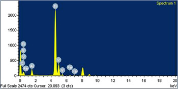
Since titanium belongs to an allotropic material, the phase transformation and the phase distributions are dependent on the α, β agents. The α and β stabilizing agents are diffused through the matrix while the FZ starts cooling from the melting temperature (T 1660 °C) to phase transformation temperature (T 882 °C). TEM/energy dispersive X-ray (EDX) spectra obtained from the FZ of Ti–6Al–4V alloy are illustrated in Fig. 4. Apart from the matrix (titanium), more quantity of β-stabilizing agent i.e., vanadium is identified. The presence of aluminum (α-stabilizer) was also detected in FZ with below average amount. Little amount of iron (Fe) with 0.86 (wt%) was spotted in the FZ. It is reported that base metal contained a small amount of iron at the matrix' (refer Table I).
TEM/energy dispersive spectroscopy (EDS) spectra of Ti–6Al–4V at FZ.

C. Microhardness measurements
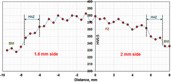
Hardness survey is carried out at a middle portion of the cross-section as depicted in Fig. 5. The hardness of the FZ is remarkable and is higher than the base metal. The maximum hardness value at the FZ is 383 and 330 HV in base metal. The difference in hardness values between FZ and base metal is 45 HV. The HAZ is located a few millimeters apart from the weld centerline and received moderate heat flux. This leads to softening of the area under the influence of heat which increases the hardness value of 355 HV at the HAZ. A few hard spots about 383 and 355 HV are measured at the FZ and HAZ of the weldment.
Typical microhardness profile obtained across the TWB.

The FZ exhibited 11.7% higher hardness value than the base metal. Overall, the hardness value fluctuates within a wide span in HAZ and FZ of the joint. Microhardness depends upon the growth of microstructures. Reference Liu, Zhou and Liu23 This microstructural evolution is attributed to the localized heat input of the welding process and cooling rate as reported by the examiners. Reference Squillace, Prisco, Ciliberto and Astarita24,Reference Caiazzo, Curcio, Daurelio and Memola Capece Minutolo25 Balasubramanian et al. reported that compared to the GTAW process higher hardness values are obtained by EBW and LBW at the FZ. Reference Balasubramanian, Balakrishnan, Balasubramanian and Muthu manickam26 The faster cooling rate of the beam welding results in higher hardening in the weldment. This is owing to the presence of the martensitic structure in the FZ. Reference Akman, Demir, Canel and Sinmazçelik27,Reference Wanjara, Brochu and Jahazi28 From hardness, the slow cooling rate of the GTAW restricts the formation of martensite in titanium weld. From Fig. 3 it was clear that there is no evidence for the formation of the martensitic structure at the FZ.
D. Tensile test
The joint quality of the TWB is studied by conducting the transverse tensile test on the butt joints. The tensile test samples are prepared under ASTM standard (ASTM E8-04). The testing specimens are carefully clamped and aligned onto the testing machine.
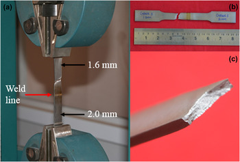
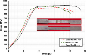
A constant strain rate of 1 mm/min was applied to the specimen. To understand the structural behaviors of TWB, uniaxial tensile test is carried out. The stress–strain graphs are plotted and compared with the 1.6 and 2 mm thickness parent metal. The fracture appeared at the parent metal indicates that weld defects have the least influence on the tensile performance as displayed in Fig. 6. The data agreed that after GTAW process, the welded region hardened. Meinders et al. reported that failure of TWB in the thinner section is a common phenomenon due to the difference in the area. Reference Meinders, Van den Berg and Huetink29 This is attributed to the fact that the thinner section reaches the ultimate load first while at the same time the thicker section still absorbs the load. Later in thinner section, the cracks are developed by initiating the microlevel cracks and voids in soft section. It is confirmed from the tensile test results as showed in Fig. 6(c) that the failure occurred in thin (1.6 mm) base metal. From the stress–strain graph (Fig. 7), TWB indicates an ultimate tensile strength of 982 MPa. Base metal of 1.6 and 2 mm showed 948 and 993 MPa, respectively. The strength of the TWB is 3.58 % higher than that of the thin sheet (1.6 mm) and 1.10 % less than that of the thinner (2 mm) sheet. Base metals and TWB are fractured with an angle of 45° orientation to loading condition.
Transverse weldment subjected to tensile test (a) fractured specimen with grips, (b) broken specimen with 45° orientation, and (c) magnified view of the fractured surface.

Stress–strain graph of base metals and TWB.

The greater strength of TWB is due to the higher amount of hardness values (383 HV) at the FZ. Thus increased hardness value at the FZ improves the fracture toughness TWB. This leads to the production of higher strength for TWB. Despite a slight variation in elongation, TWB is observed to be the strongest material.
1. SEM fractography
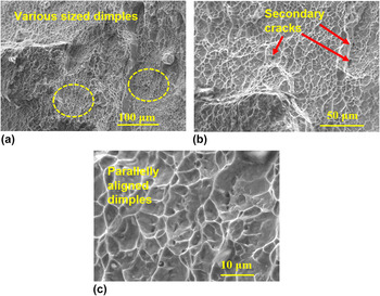
The tensile test showed slight strength deviations between base metals and TWB made with 1.6 and 2 mm thickness sheets. The elongation of the TWB is reduced but in the mean time their toughness increased. During external loading, non-uniform stress gradients are produced in the TWB because of the geometrical variation. To understand these changes, fracture surfaces obtained from the tensile test are investigated through SEM. The fracture surfaces of the base metals and TWB are analyzed at various magnifications. At higher magnifications, insignificant, narrow dimples revealed a ductile fracture which is visible due to the void coalescence. This is because of the statistic that at low magnifications, relatively less ductile samples reveal faceted appearance indicating the fracture. Fracture surface examination reveals that ductile fracture occurs at the TWB as shown in Fig. 8. Fracture occurs at the thinner section (1.6 mm) and it appeared 12 mm away from the weld line. Figure 8(a) shows the various sized dimples present at the fractured surface. The secondary cracks aid the energy and it promotes the crack propagations. These appearances represent that higher strength and lower ductility is achieved by the TWB [refer Fig. 8(b)]. As observed in the fractography, the ductile failure arises by microvoid nucleation, growth, and coalescence. The microvoids originated at the high strain concentrated areas which tend to promote the void coalescences. From the higher magnification Fig. 8(c), a few secondary dimples are identified and these dimples are parallelly aligned. Due to these facts, the strength of the TWB is greater than the 1.6 mm base metal.
(a,b,c) SEM images of fractured surface.

E. Cupping test
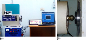
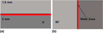
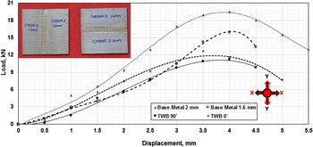
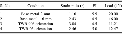
Erichsen cupping test is conducted to study the formability behavior of sheet metals. According to the ASTM E 643-84 standard the workpiece is cut into the size of 70 mm × 70 mm by using EDM. The detailed photographs of Erichsen cupping test are illustrated in Fig. 9. Cupping test is conducted on the 1.6 and 2 mm base metals. In TWB, the cupping test is conducted with different orientations (0°and 90°). Reference Babu, Narayanan and Kumar7 The schematic diagram of TWB made with different orientations is shown in Fig. 10. The base metal of 2 and 1.6 mm thickness showed an Erichsen index (EI) of 5.5 and 4.5, correspondingly. Similarly, TWB made with different orientations (0° and 90°) shows an EI of 5 and 4.5. The results obtained from the Erichsen cupping test are displayed in Fig. 11. From Fig. 11, it is observed that the base metal of 1.6 and 2 mm absorbed the maximum load of 16 and 20 kN, respectively. The weld with 0° orientation absorbed maximum load carrying capacity of 12.47 kN. However, the weld made with 90° orientation carries a load of 11.21 kN only. In cupping test, bi-axial tension is experienced by the testing specimens and the schematic diagram is presented in Fig. 11. The strength of TWB depends on the load carrying capacity of the thinner sheet. This lowers the strength of TWB as compared to their base metal. The weld with different orientations produced 10% reduction in their load absorption capacity. The inhomogeneous deformation and strength reduction are mainly caused by the weld line deviations and seam quality. Reference Wu, Gong, Chen and Xu30
Erichsen cupping test setup.

Specimen preparation for cupping test (a) 0° orientation and (b) 90° orientation.

Load versus displacement curve.

Figure 12(a) and 12(b) show the results for base material samples and TIG welded samples in respect of formability. In both cases, the greatest deformation in the part is seen to be in the center region and the cracks are initiated across the weld zone and it propagates towards the base metals.
Fractured specimen with indication of cracks (a) base metal and (b) TWB.

The reason for this deformation is the molecular shear of imperfectly oriented crystalline chains. As a result, the de-homogenization of the microstructure occurs, leading to the presence of more stress-induced microcracks during the stretching of welded joints. Therefore, the process has to be designed such that no major stretching is introduced near to the weld lines. Specimens are grid marked with a circle diameter of 2 mm by laser to measure the major and minor strains after the execution of cupping test. Reference Keeler31 The marked grids are elongated with respect to the applied loading condition and produced tension–tension failure. These dimensional changes caused by the cupping test are measured from the grids. These measurements are converted into strain ratio for understanding the formability of the sheets and it is listed in Table III.
Erichsen test results for base metal and TWB.

Specimen with 2 mm thick sheet showed a less strain ratio of 1.16. Next to this, 1.6 mm and TWB made with 0° orientation shows that the strain ratio is 2.43 and 2.46. Among all, TWB made with 90° orientation produced a more strain ratio of 3.04. In tension–tension failure, the major and minor grids are elongated bi-directionally. So that strain ratio is inversely proportional to the formability. However, in the case of tensile test, the workpiece experienced tension/compression failures. The reduction in formability depends on the TR, testing conditions and welding conditions on TWB. Reference Kamp, Celotto and Hanlon32–Reference Chan, Chan, Cheng and Lee34 Weldment is the region to withstand most of the stress. Obviously minimum strains are attained during the forming process that is evident from the above results. The result suggests that the mechanical character of the welded part is of good condition while Table III shows the result of testing of TWB specimen for two different orientations and base material of two different thicknesses. It depicts that Erichsen number or index for TWB samples is observed to be not less than that of the base metal.
IV. CONCLUSIONS
TWB with the thickness of 1.6 mm and 2 mm for Ti–6Al–4V alloy is successfully fabricated by using GTAW process with predetermined parameters. This study covers the formability limits for TWB; in addition to that microstructural studies are carried out to understand the effect of GTAW process. Based on these characterizations following results are obtained.
-
(1) A defect free acceptable quality TWB is obtained by using 1.6 and 2 mm thin sheets of Ti–6Al–4V alloys. The macrostructure of the weld displayed that the weld seam is well connected.
-
(2) The microstructure of the FZ showed that grain coarsening is identified at FZ. The TEM images indicated that α-grains are covered with β-grain boundary to restrict the dislocations.
-
(3) Hardness value is higher in at the FZ compared to HAZ and base metal is due to the presence of α-grains. A lower hardness value of 355 HV was measured at the HAZ and 330 HV at FZ.
-
(4) The joint fabricated by GTAW process exhibited an ultimate strength of 982 MPa and enhanced 3.58 % more than the 1.6 mm and 1.10% less strength than 2 mm thin base metal. The presence of secondary cracks is identified through SEM; this is attributed to the less elongation of TWB.
-
(5) Erichsen cupping test showed that formability (EI) of the TWB is observed to be not less than the base metal. According to the weld orientation, TWB made with 0° showed better formability. The reduction in formability is mainly due to the TR and microstructural changes in the weldment.
ACKNOWLEDGMENTS
The authors would like to thank Technical Education Quality Improvement Programme (TEQIP) and National Institute of Technology, Tiruchirappalli for providing the fund in order to carry out the research work.