


Introduction
Apollonia (Lat. 32o 54′ 16″ N. Long. 21o 58′ 12″ E), situated on the coast of Libya east of Benghazi, served as the harbour and military port for Cyrene, a city located approximately 15 km inland on the Jebel Akhdar plateau (Sintes Reference Sintes2025). Pottery of the eighth century BC has been found at Apollonia (Kenrick, Reference Kenrick2013, 255) suggesting activity at the coast prior to the formal foundation of Cyrene in 631 BC. According to Herodotus (Book IV, chapters 152–59, Reference Herodotus1925), Cyrene was founded by Battus from Thera, a story later confirmed by a fourth-century inscription found at Cyrene. Baragwanath discusses Herodotus’ account in relation to other classical sources, including Persian attempts to establish a base in Libya (Baragwanath Reference Baragwanath, Constantakopoulou and Fragoulaki2020). Cyrene grew despite periods of internal conflict, leading to the foundation of more Greek cities within a 50–100 km radius. Further immigrants joined Cyrene from mainland Greece, strengthening its economic base. The city’s prosperity was based on the export of agricultural produce and the trade in silphium, a medicinal plant highly valued across the Mediterranean. From its earliest years, Cyrene therefore relied on its port at Apollonia to maintain maritime connections. A Laconian wine cup illustrates the early significance of this; it is painted with a scene of King Arcesilaus II, of Cyrene (560–550 BC) supervising the loading of silphium onto a ship. By the fifth century BC Cyrene was the dominant city of the Pentapolis, and this position can probably be associated with the need for a military port at Apollonia (Boardman Reference Boardman1998, 185–88).
Following Cyrenaica’s absorption into the Roman Empire in 96 BC (Kenrick Reference Kenrick2013, 5), Apollonia continued to serve as Cyrene’s main port. After 395 AD Cyrene was ruled from Constantinople, within the eastern Roman Empire. Apollonia’s prosperity rose and fell with that of Cyrene but grew in the Byzantine period when Cyrene was in decline. It became capital of the Libyan Pentapolis in the middle of the fifth century AD. Despite the city’s substantial fortifications, the Byzantine governor abandoned Apollonia when it was attacked by the Arabs in 643 AD. Over its 1,200 years of occupation, Apollonia underwent repeated transformation, with successive reconstructions of its harbour basins, defences and infrastructure.
Considering Apollonia in the wider context of the study of ancient harbours, we note that plans of ancient Greek harbours from the Classical to Hellenistic and Roman Imperial periods have been much discussed in the literature. Sources include, inter alia (Lehmann-Hartleben Reference Lehmann-Hartleben1923; Poidebard Reference Poidebard1939; Poidebard and Lauffray, Reference Poidebard and Lauffray1951; Flemming, Reference Flemming1959, Reference Flemming1960, Reference Flemming and du Plat Taylor1965b; Jameson, Reference Jameson1969; Frost, Reference Frost1972; Flemming, Czartoryska and Hunter Reference Flemming, Czartoryska, Hunter and Blackman1973; Goodchild et al. Reference Goodchild, Pedley, White and Humphrey1976; Flemming Reference Flemming1978; Flemming, Raban and Goetschel Reference Flemming, Raban and Goetrschel1978; Hadjidaki, Lianos and Edwards Reference Hadjidaki, Lianos and Edwards1985; Keay et al. Reference Keay, Millett, Paroli and Strutt2005; Kenrick Reference Kenrick2009; Baika Reference Baika, Blackman and Rankov2013; Morhange, Marriner and Carayon Reference Morhange, Marriner, Carayon, Carcaud and Arnaud-Fassetta2015; Yorke and Davidson Reference Yorke and Davidson2017; Chapkanski et al. Reference Chapkanski, Goiran, Rosa, Kay, de Graauw, Gallet, D’Ottavio and Keay2021; Marriner et al. Reference Marriner, Morhange, Boudagher-Fadel, Bourcier and Carbonel2005).The organisation of maritime services within a Roman port is described by Arnaud and Keay (Reference Arnaud, Keay, Arnaud and Keay2020). A catalogue of ancient ports, harbours and anchorages is provided by de Graauw (Reference Graauw2024).
Since 2500 BP the coast of Apollonia has been inundated by more than 2.4 m. Today, the dominant visible features are the intensely-quarried and excavated islands that have been carved to leave walls and work spaces. The precise magnitude of displacement and the possibility of multiple vertical movements will be discussed later. To quote Sintes (Reference Sintes, Blackman and Lentini2010, 83): ‘It is due to a phenomenon of subsidence that began in the Quaternary period that Apollonia, today half under the waves, presents submerged architectural remains that are among the most important in the Mediterranean.’
The long-term occupation and coastal adaptation at Apollonia have altered the pre-settlement landscape that would have been encountered by Greek settlers arriving in Cyrenaica. Today, the topography that confronted the settlers has been concealed by sea level change and destroyed by the quarrying and carving of the islands. The answer to some of the questions about the pre-settlement landscape of Apollonia may lie underwater where early ashlar foundations rest directly on bedrock.
Previous authors (Baika Reference Baika, Blackman and Rankov2013; Beechey and Beechey Reference Beechey and Beechey1828; Garlan Reference Garlan1985; Goodchild et al. Reference Goodchild, Pedley, White and Humphrey1976; Laronde Reference Laronde1985, Reference Laronde1987, Reference Laronde1990; Sintes, Reference Sintes, Blackman and Lentini2010) theorised on the location of the first secure anchorage or harbour, the first managed harbour entrance, the first breakwaters and subsequent re-alignment of the harbour basins. Laronde observed that research throughout the twentieth century revealed important facts, but left completely in the dark the evolution of the early settlement from the arrival of Battus and his companions (Reference Laronde1985, 96). According to Sintes: ‘The material evidence is quite limited for the first centuries, even confused, and we have to wait until the Hellenistic for the veil to lift’ (Reference Sintes, Blackman and Lentini2010, 86). The remains are more substantial from periods after a fortified city wall with towers was built in the Hellenistic period in the second half of the second century BC (Garlan Reference Garlan1985), and this included the solid ashlar towers that protect the channel between the harbours.
In this paper we attempt to reconstruct the coastal topography as found by the Greek settlers and determine their priorities for creating a safe harbour. We will provide new offshore data and aim to explain the probable evolution of the harbours in the first few centuries after colonization. Our initial data derives from the Cambridge team that carried out fieldwork at Apollonia in 1958 and 1959 (Flemming Reference Flemming1959; Flemming Reference Flemming and du Plat Taylor1965b, Reference Flemming2021). More recent material comes from the MA thesis about the port of Apollonia by Boyadem (Reference Boyadem2022) as well as newly-collected survey data gathered by Boyadem in 2025.
Background
Geology, geomorphology and relative sea level (RSL) of the study area
The south-east Mediterranean coast is typified by active dune ridges and submerged and uplifted fossil calcareous aeolianite ridges, often slightly offset at an angle to the present coast. These ridges in the Eastern Mediterranean are named kurkar (Tsoar Reference Tsoar2000; Bird Reference Bird and Schwartz2005). Depending upon the angle between the ancient ridge and the modern coastline, the effect is to create a chain of offshore islands, e.g. Sabratha (Kenrick Reference Kenrick2009), Tyre (Marriner et al. Reference Marriner, Morhange, Boudagher-Fadel, Bourcier and Carbonel2005); a row of small coastal headlands and bays, e.g. Ptolemais (Yorke and Davidson Reference Yorke and Davidson2017); or a re-entrant sheltered lagoon, e.g. Apollonia.
The coast of Cyrenaica is seismically active, and seismicity maps show epicentres on the coast on all timescales (Suleiman, Albini and Migliavacca Reference Suleiman, Albini and Migliavacca2004; Al-Heety Reference Al-Heety2013; Arsenikos et al. Reference Arsenikos, Frizon de Lamotte, Chamot-Rooke, Mohn, Bonneau and Blanpied2013; Ben-Suleman Reference Ben-Suleman2006).The coastal zone exhibits a network of braided normal faults that accommodate the uplift of the central Cyrenaica Inverted Basin to the south, and the subsidence of the Mediterranean continental shelf into the Mediterranean Furrow to the north. These processes are described by Ambraseys (Reference Ambraseys1994) and Ambraseys et al. (Reference Ambraseys, Jackson and Melville2002). The driving force is convergence of the African and Eurasian tectonic plates. The normal faults are reactivated by a right-lateral strike-slip tendency along the coast. Most recent earthquakes are less than a magnitude of 3–4, except for the 1963 Al-Marj earthquake (Suwihli and Paradise Reference Suwihli and Paradise2020). However, some earlier occurrences caused considerable damage. Historical and archaeological data suggest that an earthquake struck Cyrenaica in 262 AD, with several during the fourth century AD (306–310, 361–363, 365 AD) and another at the end of the fourth century (Suleiman, Albini and Migliavacca Reference Suleiman, Albini and Migliavacca2004). Most of the coastal faults show a downthrow to the north, and the variability of motion results in pockets of uplift and subsidence. Most displacements reported in this paper may have been caused by multiple events of smaller vertical magnitude. We do not attempt to ascribe a particular displacement to a particular recorded earthquake.
RSL change on the coast may result from several processes: a regional or global rise in sea level relative to the centre of the Earth, subsidence of the land due to tectonic faulting or compaction, or sediment accumulation causing isostatic subsidence or compaction. The coast of northern Cyrenaica is steep and rocky, with minor accumulation of coastal sediments in recent millennia. Since the end of the last Ice Age (ca. 21–18,000 years ago), a driver of RSL change has been the addition of meltwater to the oceans, isostatic uplift/subsidence in response to shifting ice and water loads and the movement of water within ocean basins as a result of changes in the gravitational attraction of large ice masses as they melted. This process is known as Glacial Hydro-Isostatic Adjustment (GIA). Key studies relevant to the calculation of GIA include Walcott (Reference Walcott1972), Lambeck (Reference Lambeck1995), Lambeck (Reference Lambeck and Chappell2001), Lambeck et al. (Reference Lambeck, Purcell, Johnston, Nakada and Yokoyama2003, Reference Lambeck, Rouby, Purcell, Sun and Sambridge2014), Argus et al. (Reference Argus, Peltier, Drummond and Moore2014), Peltier et al. (Reference Peltier, Argus and Drummond2015) and Spada and Melini (Reference Spada and Melini2022, Reference Spada and Melini2019).To clarify the specific influence of GIA on Apollonia for the last 5,000 years, we asked Melini and Spada to calculate the relative sea level using two widely-accepted, recent geophysical models. Melini produced the graphs shown in Figure 1.
Glacial Hydro-isostatic Adjustment (GIA) curves of relative sea level change at Apollonia generated using the SELEN4 Fortran programme (Spada and Melini Reference Spada and Melini2019) and implementing ICE-6G_C geophysical model data of the Peltier group (Argus et al., Reference Argus, Peltier, Drummond and Moore2014; Peltier et al., Reference Peltier, Argus and Drummond2015) and the Lambeck and Chappell ANU data (Lambeck and Chappell Reference Lambeck and Chappell2001). (Melini personal communication 2020). At 2500 BP the models indicate 0.5 m and 0.05 m, with an average of 0.275 m; at 2000 BP the models indicate 0.2 m and 0.02 m, with an average 0.11 m. These values are considered small within the error margins of tectonic displacement estimates.

At 2500 BP the curves indicate 0.5 m and 0.05 m, with an average of 0.275 m; at 2000 BP the curves indicate 0.2 m and 0.02 m, with an average of 0.11 m. The bulk of submergence discussed below must therefore be due to tectonic activity. These values are small compared with the tectonic displacements discussed below and are within the error margins of the tectonic displacement estimates. The overall observed subsidence of the order of 2m to 3m fits well within the range of documented tectonic activity at sites along the Cyrenaican coast (Yorke and Davidson Reference Yorke and Davidson2017; Pizzinato and Beltrame Reference Pizzinato and Beltrame2012; Kenrick Reference Kenrick2013).
Timing of tectonic displacements
Apollonia was an important city as late as the sixth century AD. The city underwent rebuilding at several stages, and these could have been related to episodes of tectonic uplift or subsidence. This is supported by the difference in level of the slipways built in the early fifth/fourth century BC, and the piscina or fishtank which dates from the Roman Imperial period. The fishtank indicates a sea level change of 2.8 m–3.0 m (Flemming Reference Flemming1971, Reference Flemming2021).
The glass ingot found by Cambridge divers in 1959 dates from the fourth–fifth century AD (Flemming Reference Flemming2021, 463; Freestone Reference Freestone2025) showing that the harbour was still active at this date. Sintes (Reference Sintes, Blackman and Lentini2010, 86) reports that DRASSM (Département des Recherches Archéologiques Subaquatiques et Sous-Marines) divers excavated a trench between the Block Forts at the entrance of the western harbour. The trench uncovered evidence that in the Byzantine period, probably around the fourth–fifth century AD, further uplift occurred of 1.2 m, perhaps in several events, and in the sixth and seventh centuries AD the entrance had been closed quickly with reused building material. The French divers estimated a maximum uplift of 3.50 m (Laronde Reference Laronde1990; Laronde and Sintes Reference Laronde and Sintes1998). They based this on indications of lithophaga borings on the sides of the fortified towers facing the channel. Baika (Reference Baika, Blackman and Rankov2013, 294) describes the inner harbour as being disused and dry at this date. The French concluded that there is additional support for a total change of level of 3.70–3.80 m since the beginning of the Christian era. It follows that the final subsidence must have occurred after ca. 600 AD, although a more precise date cannot at present be established.
At an unspecified date, perhaps around the eighth–ninth centuries AD, tectonic subsidence of 3.8 m occurred. This is a major tectonic event by Mediterranean standards, comparable with the great Crete uplift of 365 AD (Stiros Reference Stiros2010), although it may represent multiple subsidence episodes. The cumulative effect of these displacements is + 0.2 +1.2 – 3.8 = –2.4 m (uplift positive, subsidence negative). That is the present depth of displacement of the slipways on Hammam Island. These values are best-fit approximations: the source estimates are imprecise and not fully mutually consistent, and the figures adopted here are chosen to be compatible with the observed 2.4 m displacement of the slipways, as indicative magnitudes rather than measured quantities. The changing relative sea level, from whatever cause, is emphasised by the apparent contraction of the diameter of the harbour shown in Figure 2. The circumference shown in red is adjacent to all the major waterfront buildings and overlaps the lower part of the slipways. The circumference in green is adjacent to a more varied set of smaller structures; numerous walls have been built both on top of the slipways and below their lower ends, rendering them unusable.
Map illustrating contraction of the harbour basin, with later small-scale buildings superimposed over the slipways and a reduced perimeter relative to earlier structures on the Western Basin margin. The red line indicates the sixth-century BC shoreline; the green line marks the Early Roman Imperial shoreline.

Figure 2 Long description
The map of Apollonia illustrates historical changes in the shoreline and tectonic subsidence effects. A red line marks the sixth-century BC shoreline, while a green line indicates the Early Roman Imperial shoreline. The map shows the contraction of the harbour basin, with later small-scale buildings superimposed over the slipways. The perimeter is reduced relative to earlier structures on the Western Basin margin. Tectonic subsidence of 3.8 meters is noted, affecting the slipways on Hammam Island. The map includes various labeled areas such as ′Inner Harbour′ and ′Outer Harbour′ and features like ′Slipways′ and ′Quay′. The map grid is marked with coordinates and the layout includes arrows indicating directions and various annotations related to historical and geographical features.
The contraction of the inner harbour basin could be caused either by tectonic uplift of about 0.2–0.5 m, or by the partial infilling of the basin by rubbish and constructional debris. The latter seems unlikely. The evidence for changes of RSL is still imperfect, but the data are consistent with a tectonic uplift of the order of 0.2–0.5 m at the beginning of the Imperial period, with subsequent further uplift, until final subsidence of the order of 3.8 m after 600 AD.
Wind and wave climate at Apollonia
Visitors to Apollonia have observed the dominant north and north-west winds which make the present harbour unsafe. We quantify this with wind data (Figure 3a,b). The wind can be strong in summer, and this would have made ship management difficult during export of agricultural produce to the north Mediterranean cities.
(a) Wind direction and speed (km/h) for Benghazi, expressed as hours per year. (b) Wind direction and speed (km/h) for Tobruk. Circles indicate annual wind duration by direction, in 500-hour increments up to 2000 hours per year.

Figure 3 Long description
The image A showing a polar bar chart titled “Benghazi”. Direction labels around the circle include N, NNE, NE, ENE, E, ESE, SE, SSE, S, SSW, SW, WSW, W, WNW, NW and NNW. Concentric circles are labeled 500, 1000, 1500 and 2000. A legend titled “Wind Speed” lists: less than 2.1 kilometers per hour; 2.1 to 5.7 kilometers per hour; 5.7 to 10.3 kilometers per hour; 10.3 to 20.6 kilometers per hour; 20.6 to 30.9 kilometers per hour; 30.9 to 40.1 kilometers per hour. Stacked radial bars appear in multiple directions, with the tallest stacks in the N to NNW sectors, reaching close to the 2000 circle. Additional stacks appear in NW and WNW and smaller stacks appear in other directions. The image B showing a polar bar chart titled “Tobruk”. Direction labels around the circle include N, NNE, NE, ENE, E, ESE, SE, SSE, S, SSW, SW, WSW, W, WNW, NW and NNW. Concentric circles are labeled 500, 1000, 1500 and 2000. A legend titled “Wind Speed” lists: less than 2.1 kilometers per hour; 2.1 to 5.7 kilometers per hour; 5.7 to 10.3 kilometers per hour; 10.3 to 20.6 kilometers per hour; 20.6 to 30.9 kilometers per hour; 30.9 to 40.1 kilometers per hour. Stacked radial bars are concentrated mainly in the N to NNW sectors, with the tallest stack near NNW reaching between the 1500 and 2000 circles. Smaller stacks appear near N and NW, with minimal stacks in most other directions.
Figure 3a and 3b are wind roses for Benghazi and Tobruk on either side of Apollonia. The north wind dominates the annual wind pattern for Benghazi; the wind blows from the north and north-west for nearly 60% of the time. At Tobruk the north-west wind dominates. Taken together, the two locations confirm that the partial shelter provided by the islands at Apollonia can only be converted into a useful harbour by blocking the north-west- and north-facing gaps.
Barbariol et al. (Reference Barbariol, Davison, Falcieri, Ferretti, Ricchi, Sclavo and Benetazzo2021) published data showing seasonal wave heights in the Mediterranean, including the coast of Cyrenaica. Their Figure 4 shows that the coast of Cyrenaica is exposed to high wave energy. Key data from Barbariol et al. (Reference Barbariol, Davison, Falcieri, Ferretti, Ricchi, Sclavo and Benetazzo2021) have been extracted by Westley et al. (Reference Westley, Nikolaus, Emrage, Flemming and Cooper2023) for the coast of Cyrenaica. For average winter conditions (November–March) the significant wave height (Hs) reaching the coastline is 1.25 m for the fiftieth percentile, and >4 m for the ninety-ninth percentile. These can be respectively regarded as representative of average and extreme conditions. Summer (June–August) Hs is lower: 0.75 m for the fiftieth percentile and 2 m for the ninety-ninth percentile. Similarly, maximum individual wave heights (Hmax) during winter range from 2.5 m–8 m and during summer from 1.75 m–5 m. In both cases, the range reflects the fiftieth and ninety-ninth percentiles.
Hammam Island, the western of the two principal islands at Apollonia, showing submerged remains photographed in 1958 using a polarising filter. Foundations are visible in shallow water near the beach and within the channel between the harbour basins. The remnant rock wall was still left in situ after extensive excavation of the island, including the slipways; this wall was later destroyed. The heads of the slipways are visible.

Previous work
The ruins of Apollonia were first described by travellers such as della Cella (Reference Cella(1819) 1912, 92–96) and by Beechey and Beechey (Reference Beechey and Beechey1828, 497–98) who observed the submergence of ruins and mapped some of them. In 1958 and 1959 Flemming led divers from Cambridge University to undertake the first systematic underwater survey of the site to produce a map of the ashlar foundations and rock-cut features covering an area of 28 hectares, including the two harbour basins (Flemming Reference Flemming1959; Reference Flemming1960; Reference Flemming and du Plat Taylor1965b; Reference Flemming1971, 95–135; Reference Flemming2021, 30–60). Although ashlar walls were usually only preserved one or two courses in height, a few structures were found stratigraphically superimposed, and the solid ashlar tower foundations guarding the channel between the harbour basins still stand five courses high above surrounding rubble. Despite the simple equipment available in the 1950s, the accuracy of the Cambridge plan is remarkable: the outlines of major structures correspond with modern imagery to within approximately 50 cm (Figure 5a). The 1958–59 surveys include measurements of features that have since been destroyed by storms, erosion and blast fishing, or are now buried in sand. For comparison, divers have recently photographed a substantial ashlar block that is now broken into three fragments, caused by underwater explosions linked to blast fishing (Boyadem 2025, personal communication).
(a) Plan of the ruins of Apollonia surveyed by the Cambridge diving team in 1959 (after Flemming Reference Flemming1960; Reference Flemming1965b). The hatched area indicates the modern beach; submerged remains lie to the north and later terrestrial structures to the south. Two harbour basins are shown. Present water depths (m) are indicated, with contours at 2.0 m and 4.0 m around the inner (western) harbour. The original north arrow is misaligned c. 10° west of true north. Hammam Island and Sharkea Island are labelled. (b) Satellite image from 2021 showing the main features described in this article (Google Earth Pro, CNES/Airbus imagery, Apollonia Libya, Image date: 20/09/2021, Accessed: 26/05/2026).

Figure 5 Long description
A) A plan of the ruins of Apollonia, surveyed in 1959, shows the layout with a hatched area indicating the modern beach. Submerged remains are to the north and terrestrial structures are to the south. Two harbor basins are depicted with water depth contours at 2.0 m and 4.0 m around the inner harbor. The map includes Hammam Island and Sharkea Island, with a misaligned north arrow. B) A satellite image from 2021 displays the main features of Apollonia, including Hammam Island, Sharkea Island and the Outer Harbour. The image highlights the coastal layout and surrounding water bodies.
The Cambridge survey used a telescopic alidade located at points along an 800m baseline on shore to sight onto ranging poles held on the corners of submerged buildings by divers. The repeat accuracy of re-location of successive points was equivalent to an error of +/- 20 cm on the ground. The submerged buildings to be recorded were inspected by three or four divers underwater together so that there was agreement on the position of every structure. Despite a 10° baseline deviation identified by later comparison with satellite imagery, the 1958–59 plan correlates remarkably well with recent drone imagery and Google Earth data, confirming its enduring value as a reliable record of Apollonia’s submerged remains.
Sintes (Reference Sintes, Blackman and Lentini2010, 83) remarks that: ‘In spite of inexactitudes that we will discuss later, his (Flemming’s) plan and his descriptions of ruins will remain for a long time the only, and thus precious, reference available for the submerged zone.’ The ‘inexactitudes’ refer to errors in the measurement of depth and width of the central runners in military slipways that were the focus of the Sintes paper (Reference Sintes, Blackman and Lentini2010, 91).
From the 1980s onwards, the French Archaeological Mission (Mission Archéologique Française: MAF) conducted a number of studies at Apollonia (Laronde Reference Laronde1981, Reference Laronde1983, Reference Laronde1985, Reference Laronde1987, Reference Laronde1989, Reference Laronde1990; Laronde and Sintes Reference Laronde and Sintes1998; Sintes Reference Sintes, Blackman and Lentini2010, Reference Sintes2025). Much of the work by MAF was conducted on land, but they also undertook underwater work concentrating on the excavation and mapping of submerged features, focusing in particular on the slipways on Hammam Island, the excavation of a shipwreck, the entrance channel between the two harbours and the rock-cut piscina or fishtank. In a wider context, coastal archaeological remains in Cyrenaica between Tocra and Apollonia have more recently been reviewed and assessed by Emrage and Nikolaus (Reference Emrage and Nikolaus2023), Nikolaus et al. (Reference Nikolaus, Abdrbba and Emrage2022) and Westley et al. (Reference Westley, Nikolaus, Emrage, Flemming and Cooper2023).
Current/recent work
For the present study Google Earth, low-level drone images and underwater photographs have been used to confirm the accuracy of the 1958–59 survey. The map presented in Figure 5a and its bathymetric soundings were used to identify critical areas where a reduction in water depth by 2.4 m would close an apparent entrance to the harbour or make it so shallow that boats of the Classical era could not cross it safely. To establish the topography prior to Greek settlement it was assumed that each of the high-point aeolianite dunes was of ellipsoidal shape (see below) with a highest point equivalent to the highest point still occurring on each island. The exception to this rule was Grotto Reef, where there has been erosion of the highest point of the order of at least one metre, judging from sharp pinnacles. The lateral extent of rock extraction at each aeolianite dune down to the sea floor was measured from the light-coloured fresh cut rock showing on drone images.
Boyadem landed on each of the islands and used a weighted plastic tape and horizontal level to measure the height of the summit to an accuracy of 10 cm above present sea level. Using snorkel and fin swimming, he took soundings with a weighted plastic tape at recorded points around Grotto Reef, and between Grotto Reef and Camel Shoal, with an accuracy of 20 cm. In the Northern Gap Boyadem took soundings at intervals of 20–50 m along the crest of the submerged ridge, and for 20–50 m each side of the crest. He then made soundings in the channel between Hammam Island and Sharkea Island, and in the wave traps on the outside of Grotto Reef, Hammam Island and Sharkea Island. He took underwater photographs of key features such as channels, arches, horizontal walls and large ashlar blocks. To check for the existence of a sedimentary tombolo between the mainland and Hammam Island, Boyadem made depth observations and took samples of the seabed substrate.
The site at present
The term limen kleistos, commonly translated as closed harbour, has been analysed by Mauro (Reference Mauro2024). The concept provides a useful framework for understanding the essential elements of harbour design: topography, military defence, protection from storms and the security of goods. At Apollonia we can add the safe mooring for galleys, shipsheds with slipways, protection from pirates and seaborne attack, secure entrance channels, a lighthouse and access to the Cyrenaican hinterland. The site also supported boat- and shipbuilding and repairs, creating a multifunctional maritime hub.
Apart from the two main islands, the area of the early city is currently submerged, with part of it extending southwards beneath several metres of overburden and remaining inaccessible. No underwater excavation has taken place in the last 20 years, although artefacts exposed by storms have been recovered (Boyadem Reference Boyadem2022). The defensive northern perimeter of the city curved in a semicircle from the submerged remains and residual features of Grotto Reef (Figure 6b–e) across the wide Northern Gap to Hammam Island, which had to be closed to form a harbour, and then through adaptations to the islands of Hammam (Figures 4 and 7) and Sharkea (Figure 10). Google Earth images from different dates reveal wave patterns around the islands (Figure 6a, b).
(a) Alignment of elevated points defining the fossil dune ridge adjacent to the submerged remains of Apollonia; much of the ancient city lies submerged between the mainland and the easternmost islands at the ridge terminus (Google Earth imagery). (b) Breaking waves revealing submerged rock-cut features, including the curved crest of the Grotto Reef and Camel Shoal to the north, the latter possibly part of the city defences. (c) Composite drone imagery of the Grotto Reef (2022) showing parallel rock-cut walls (cf. Figure 5), extensive carving, and two drainage corridors (outlined in yellow), one with a collapsed roof trending north-west; the curved-bounded pathway is interpreted as a wave trap with a residual north-west rock-cut breakwater. (d) Submerged corridor terminating in a rock-cut arch at the north-west end in the Grotto Reef; depth to floor slightly exceeds 2.0 m (photo SMB, 2025). (e) Rock-cut wall forming the margin of a depressed parallel structure on the east side of the Grotto Reef, with incised slots possibly for crossbeams; scale bar 1.0 m (photo SMB, 2022).

Figure 6 Long description
Insufficient visual information to describe this element accurately.
Drone image of Hammam Island (2022) showing 40 m-long slipways and extensive removal of bedrock. The submerged rock wall of the wave trap and the broken wall along the northern edge of the island are visible. Compare Figure 4 (photo SMB).

Geomorphology and pre-settlement landscape
Figure 6a shows the alignment of aeolianite residual features diverging from the mainland shore west of Apollonia, through the modern jetty area and on to the submerged rock-cut features known as Grotto Reef and Camel Shoal (see also Figure 5a, b), before reaching Hammam Island and Sharkea Island. The residual rock-carved features are vestiges of the rock in the pre-settlement ridge. The quarry cutting marks surrounding the base of each feature show the areal extent of the absent rock. For the purpose of calculation, we assume that the highest feature remaining indicates the approximate original height of the kurkar, with the exception that Grotto Reef has been eroded away at the summit.
There are five key areas of raised rock-cut topography (Figure 5b). The first lies beneath and around the modern, small concrete jetty, where quarried and carved rock surfaces are associated with submerged extraction zones and a prominent rock-cut tower or tomb, standing about 4 m above the present water level. This area is referred to as the Tower Tomb. The surrounding quarried surface is submerged to a depth of roughly 1 m. A second zone of raised topography is almost entirely submerged, with only the summit breaking the surface of the water by about a metre in calm conditions. This area includes the second and third zones: Grotto Reef and Camel Shoal respectively, corresponding to grid squares B3–4, C3–4 and A4–5 on Figure 5a. The fourth and fifth high topographic elements are Hammam Island and Sharkea Island.
Methodology
We used the area of excavated rock on the sea floor around the existing remnants of each island as an estimate of the original ground area of the aeolianite dunes. Based on these measurements, and the height of remaining extant features, we estimated the volume of the original ridge, and the volume of excavated rock. From these values, combined with wind and wave data, we aimed to assess the objectives and procedures of the early harbour engineers. Firstly, we addressed the ancient, excavated areas and the residual purposive carved structures left in situ in the solid rock. The term ‘quarrying’ is used only where it is certain that stone was removed solely for construction elsewhere and that the resulting relic feature had no designed function. We will also analyse the function of the residual constructions where relevant and attempt to describe a probable sequence of the early phases of the city and port construction. Excavated rock provided rubble to protect the harbour basins with breakwaters and also squared ashlar masonry for the foundation of the early buildings that can be found on the sea floor.
Residual rock-cut features
The footprint area was obtained for each carved and quarried zone by use of drone images to identify light-coloured excavation areas on the sea floor round the island, and by locating the outer edge of the curved residual rock-cut breakwaters round the wave traps on each island. The identified area was approximated as an ellipse with semi-axes of length a and b, and the volume was approximated as half of an ellipsoid of semi-axes a, b and c, where c is the height. Dimensions in metres were derived from Google Earth and the 1958/59 map. This approximates quantities that are not known and cannot be re-created exactly. To assume a flat-topped dune mass would be an overestimate of the probable volume, while a pointed pyramid or cone shape would be an underestimate. Therefore, half of an ellipsoid is a reasonable intermediate estimate. The area of an ellipse is π ab, and the volume of an ellipsoid is 4/3 π abc, where c is the vertical semi-axis. These formulae are correct even when the axes are asymmetric and do not intersect at their mid-points (Flemming Reference Flemming1965a) provided that each quadrant is bounded by an elliptical curve.
The proportion of a calcified dune mass that has been excavated was estimated from the following factors, using Google Earth, drone images and the 1958/59 map: proportion of total footprint excavated down to the contemporary sea level; proportion excavated below contemporary sea level; volume excavated from wave traps calculated from length, width and depth; volume excavated above wave traps as overburden within the ellipsoid; proportion excavated to create flat areas or work spaces at known height above contemporary sea level; volume of hollowed-out caverns. The estimation is approximate and has an error in the total of the order of +/- 20%. The five raised dune areas will be described in turn. The dimensions, area and volumes are listed in Table 1.
Areas and volumes of each carved and quarried aeolianite dune

1. Tower Tomb by jetty: From the Beechey and Beechey map of 1828, Google Earth and drone images ground area footprint = 285 m × 100 m. The height of the rock-cut Tower Tomb measured from photographs = 4 m, and water depth over quarrying for rock removal = 1.0 m, therefore vertical dimension semi-axis c = 5.0 m. Using the formulae above, the area is 22,384 m2, and volume is 74,613 m3. In the case of the Tower Tomb, almost the entire volume of rock has been removed, estimated at 99%.
2. Grotto Reef: This area is mostly submerged, with small pinnacles projecting 1.0 m above the surface in calm water. Breaking waves roll across the reef except in calms, and jagged pinnacles indicate that there has been erosion of the summit. There is a curved ridge that causes waves to break in windy weather (Figure 6a,b), with several large carved rock structures to seaward of it, including vertical carved surfaces, and an elongated space like a roadway and rock arches.
Grotto Reef is shown in a composite drone image in Figure 6c. The Reef was a low-lying aeolianite ridge of which the total footprint area, measured from drone images and the map in Figure 5, is 140 m by 100 m. The original height was about 5.0 m above the contemporary sea level, allowing for erosion of the summit and relative sea-level change of 2.4 m. It was therefore prone to wave run-up and overtopping. The outer side of the reef, facing the NW wind, was carved into a deep, flat-bottomed trench, protected to seaward by a residual, solid-rock breakwater, forming a large wave trap. The floor of the wave trap was probably dry in calm weather when no water was spilling over the breakwater.
On the landward side, facing into the harbour basin, there is the southern submerged corridor or channel (Figure 6d) where the roof has collapsed, but the roof was intact in 1958–59. Divers recorded film footage swimming through the rectangular corridor in 1958. This corridor appears designed for people to walk through it, but in stormy weather the wave trap would be full of water from breaking waves, and the corridor would be flooded, or could perhaps be closed with a stone door or sluice gate. Such a channel would send a current of water into the inner basin to prevent stagnation and sedimentation. A second channel to the north is shown in Figure 6d.
The southern passageway opens in the NW direction under a rock-cut arch (Figure 6d) leading into the wave trap which is about 10 m wide. The floor level is approximately 2.0 m below sea level and so would have been just dry in calm weather at the time of foundation. There are small quantities of rubble on the outer slope beyond the rock breakwater, but insufficient to have provided protection from the waves. It is probable that these blocks are debris from damage to the rock breakwater which has some irregular gaps in it.
Between the high part of the Reef and the edge of the harbour basin there are six rock-cut parallel walls (see B3-4 and C 3-4-5, on Figure 5a, b) separating depressions that could be boat-building workshops and repair docks (Sintes Reference Sintes, Blackman and Lentini2010, 85; Baika Reference Baika, Blackman and Rankov2013; Blackman Reference Blackman and Tzalas1990, 46–7; Blackman and Rankov Reference Rankov, Blackman and Rankov2013). There are incised rectangular slots in the upper edge of some of the walls which could have supported wooden crossbeams (Figure 6e). This area probably contained industrial constructions that had to be protected from overtopping waves. Given the mapped length and breadth of 140 m by 100 m, and height 5 m, the footprint elliptical area is 10,995 m2 and the volume 36,600 m3 (See Table 1).
3. Camel Shoal: This area has not been fully measured underwater, but in the view of the present analysis it was a key structure in the boundary defences of the city, and part of the high perimeter of in situ rock and rubble providing protection of the harbour against storm waves.
The footprint area of 50 m by 30 m is estimated from the Google Earth imagery in different weather conditions and the outline in Figure 5a, and the height of 3 m is estimated from observations underwater by Boyadem.
Footprint area is calculated as 1,178 m2 and volume as 2356 m3.
This calculation is based on approximate measurements and estimates, and requires further measurements, when possible.
4. Hammam Island: Hammam Island has been carved and excavated so intensely that there is hardly a square metre of the original kurkar ridge surface still uncut (see Figure 7). The dimensions of the quarried footprint are 142 m by 97 m, using drone images and Google Earth and waves breaking on rock-cut breakwater. The height of the highest point is 7.7 m above present sea level, measured by Boyadem. The ten shipshed slipways south of the island are a well-preserved feature (Goodchild et al., Reference Goodchild, Pedley, White and Humphrey1976; Flemming Reference Flemming1960, Reference Flemming and du Plat Taylor1965b, Reference Flemming1971, 103–104; Sintes Reference Sintes, Blackman and Lentini2010, 91; Baika Reference Baika, Blackman and Rankov2013, 299; Sintes Reference Sintes2025, 51–63). The sloping slipways had the function of storing warships, pentekonters and triremes out of the water to prevent fouling and decay. In most cases of known shipshed/slipways (Blackman and Rankov Reference Rankov, Blackman and Rankov2013) there was a roof structure that protected the hulls from the heat of the sun and from rain. The term ‘shipshed’ is used to describe the combined installation.
The eastern side of the original domed dune ridge has been almost entirely removed, creating a semi-rectangular space bounded on the north and west sides by artificial cliffs. Divers in this area in 1958–59 filmed these cliff faces and the quarried sea floor, in which there is an excavated rectangular depression about 5 m long, 2–3 m wide and 2–3 m deep. Notably, this feature extended below the contemporaneous sea level (Figure 7). The function of this depression is not known. Although no structures remain in the excavated area, the drone imagery shows many rectilinear features cut into the bedrock which appear more deliberate and precise than relics of quarrying alone. These features suggest that the area served a specific working purpose, though its role has yet to be determined. That this area was protected and functionally important is supported by the structures immediately to the south defined as the North Quay and esplanade by Sintes (Reference Sintes2025, 70–2).
The northern external cliff face (Figure 8a), which is 6.5 m high, is explicable as a defence against storm waves, and an obstacle to an attack by armed vessels from the sea.
(a) Northern side of Hammam Island (2003), showing a rock-cut cliff face rising 6.5 m above present sea level and the island summit at 7.7 m asl; aeolianite sedimentary banding is visible, and wave energy is dissipated on the outer submerged residual ridge (photo Kleinberg). (b) Curved wave trap protecting temple foundations at Dor, Israel, where local relative sea-level change has occurred over the past 2500 years (photo Dorit Sivan). (c) Broken wall on Hammam Island (2003) with entrances to hollow chambers; swell patterns indicate the effectiveness of the wave trap in forcing waves to break offshore (photo Kleinberg). (d) Storm-deposited debris from the collapsed back wall of Hammam Island on the slipways; half-width of slipway 2.5 m. Photograph taken in the mid-1960s, indicating collapse shortly after the 1959 Cambridge survey (photo Jean-Pierre Misson).

The main trough parallel to the cliff is 12 m–16 m wide and 70 m long (see Figure 7), calculated by comparison with the length of the slipways which were measured with a ranging rod at 40 m. Measurements with a weighted tape and photographs within the trough, taken by Boyadem, show that the depth varies from 2.2 m to 2.7 m, with an irregular floor of bedrock. In the sixth century BC, the trough would have been almost dry in calm weather, with shallow pools of sea water 20–30 cm deep. The intensive shaping of Hammam Island and the slipways is consistent with providing security for military equipment and war galleys and preventing damage from waves or attack by enemy ships. The closest comparison is with a rock breakwater and wave trap at Dor, Israel (Figure 8b). The Dor feature is smaller than that at Apollonia, but the position relative to the area to be protected is similar (Yasur-Landau et al., Reference Yasur-Landau, Shtienberg, Gambash, Spada, Melini, Arkin-Shalev, Tamberino, Reese, Levy and Sivan2021).
Referring to Figure 7, the rock-cut structures east of the deepest wave trap on the north side of Hammam Island are unexplained and have not been dived into or examined. The map from 1958–59 matches the Google Earth image, so that the general forms of the multiple pools within the trap are correct. The rocky ridge extends eastwards and terminates in a rectangular basin approximately 25 m x 10 m, with the walls partly broken.
Figure 4 includes a view of Hammam Island with a dark area in the centre of the back wall. This wall joined the two halves of the island together and was about 2 m thick. It was a residual wall of bedrock formed by extracting large volumes of rock on both sides. In Figure 7 the position of this wall shows as the flat edge of the carved rock surface at the centre of Hammam Island, but with no wall. The rock wall was destroyed after 1959, and Figure 8c shows the fractures of the bedrock where the wall was destroyed. Fragments of the wall lie on the slipways and were photographed by Jean-Pierre Misson in the 1960s (Figure 8d).
The wall was probably broken by wave action, but damage may have been caused by explosions during blast fishing. Rubble from the collapsed rock wall is scattered over the slipways (Figure 8d). Figure 8c also shows the broken doorway into rock-cut galleries, with several chambers separated by rock walls and terminating in a vertical passageway cut with footholds, like a ladder. This opens onto the top of Hammam Island. The covered storage or habitation space inside the island, and the vertical access to the top, demonstrate its strategic importance. Given the military nature of the slipways, which were common in the fifth to third centuries BC, the island was developed as a fortress to support war galleys.
The profile shown in Figure 9 depends on the estimate of the sea level when the slipways were constructed. The gradients of ancient slipways range from 15° to 2° and the Apollonia slipways are of a low gradient at 4° (Rankov Reference Rankov, Blackman and Rankov2013, 95–96). The risk of damaging a fragile hull during launch is reduced if the lower section of the slip is partly submerged so that the bow gains buoyancy more quickly. At Apollonia this would be obtained by having 30–40 cm of water at the lower end. This equates to a net change of relative sea level of 2.4 m. Thus, the height of Hammam Island in the seventh century BC was 10.1 m.
Profile of excavation and rock-cutting on Hammam Island. The shaded area indicates remaining bedrock following removal of quarried material. The dotted curve reconstructs the pre-cutting island profile. Vertical scale exaggerated 2:1.

Figure 9 Long description
The cross-sectional excavation profile of Hammam Island illustrates the relationship between sea level changes and structural features. The diagram includes a vertical scale exaggerated two to one and a horizontal scale, both in meters, with tick marks at intervals of five meters. The profile is oriented with north to the left and south to the right. The original island profile is depicted with a dotted line, while the present sea level is shown as a solid line and the old sea level is indicated with another dotted line. A rock wall is positioned above the present sea level, featuring a doorway and hollow chambers. To the left, a ridge of a wave trap and the wave trap itself are marked. Slipways extend downward toward the sea, illustrating their interaction with the water levels. The diagram communicates how the remaining bedrock and constructed features relate to the historical and current sea levels, providing insight into the island′s geological and structural changes over time.
We calculated the area and volume of rock from Hammam Island. The quarried footprint is an approximate ellipse enclosing an area of 1.1 hectare. The volume of the aeolianite dune is approximately 72,800 m3.
5. Sharkea Island: The rock-cut technology of Sharkea Island (Figure 10) is similar to Hammam Island. On the north side there is a trough and protecting wall like the same feature on Hammam Island. The trough is 13 m wide. The other faces of the island have been cut into vertical cliffs. The highest point of the island is 9.3 m above sea level. The quarried footprint on the sea floor was measured from drone images and the waves breaking on the northern rock-cut breakwater. The dimensions show that the original aeolianite island was 77 m x 86 m. There is a set of three parallel rock-cut quarries south of the island, with blocks of ashlar ready to be cut away. There are ashlar walls adjacent to the base of the cliff on the south side. At the eastern end of the island there are three rectangular tanks cut in the bedrock with the edges of the tanks underwater.
Sharkea Island (2025) showing the artificially cut vertical southern face, circular tower base and wave trap on the northern side. Rectilinear submerged cuttings and small ashlar walls are present at the base of the cliff.

The area of rock cuttings on the south side of Sharkea Island would have been close to sea level and would be suitable for buildings to support the management of small boats. The cylindrical bulge on the southern side near the eastern end of the island supports a circular foundation on the top surface, with curved incisions for ashlar blocks; these are the foundations of a tower. This could have been a lighthouse or other form of navigational aid or for signalling. The situation of the tower on the east end of Sharkea Island suggests that navigational aids guided approaching vessels to steer to the east, and not to go between the islands.
We calculate the footprint area and the volume of rock from Sharkea Island using the equations as above. Area of elliptical footprint is 5,200 m2, and the volume of the ellipsoidal dune was approximately 40,000 m3.
Summary of areas and volumes of removed rock
Table 1 lists the areas and volumes of each carved and quarried aeolianite dune. We estimate also the percentage of the volume that has been extracted and was available to build rubble moles, or to cut as ashlar building blocks. The figures have been rounded to be compatible with errors of the order of +/- 20%.
From the map in Figure 5a we can see that approximately 9 hectares of the submerged city and islands have structures, buildings, rubble breakwaters, or rock-cut structures on them, excluding the water-filled basins of the harbours themselves. Of these 9 hectares, 5 are rock-cut creations. This proportion of rock-cut features must be taken fully into account when interpreting the early centuries of the city.
The large quantities of stone removed from the aeolianite islands are more than enough to facilitate a wide range of constructions: we calculate approximate volumes of rock needed to construct proposed harbour engineering and a major ashlar structure. To close the Northern Gap with a minimal rubble mound without a raised road required a triangular cross section of 3 m high, 200 m long, and 20 m wide, making a volume of 6,000 m3. The gap between Hammam and Sharkea Islands could be closed with a steep-sided mound with dimensions of 100 m by 6 m high by 12 m wide, making a volume of 7,200 m3. The Grid Building of ashlar blocks has eight walls 50 m long, and 0.5 m wide, with walls probably 2 m high, making a volume of 400 m3.
Profile of the northern ridge
The depth of the northern ridge between Camel Shoal and Hammam Island determined the entry channels to the Western Basin by ships. Boyadem took soundings with plastic tape, accurate to +/- 20 cm, along the ridge crest and for 50 m on either side of the crest. The contoured map and profile are shown in Figure 11a and 11b. A submerged terrace of rock projects eastwards from Camel Shoal at a depth of 2.0 m to 3.0 m, leading to a trough at 6.0 m, while a ridge of depth 4.0 m separates the trough from the Western Basin. The rocky seafloor then rises steeply to Hammam Island. The trough at 6.0 m on the northern side of the ridge crest is partly filled with massive blocks of size 1.5 m to 3.0 m. This supports observations that DRASSM divers found a gap in the ridge closed with massive blocks (Sintes Reference Sintes, Blackman and Lentini2010, 88).
(a) Present water depths (m) between Camel Shoal and Hammam Island. The blue line marks the crest of the ridge separating the open sea from the western (inner) harbour basin; a gully on the north side of the ridge is infilled with large stone blocks, possibly derived from a former breakwater. (b) Depth profile along the blue transect shown in (a). The seabed is more irregular than represented, indicating potentially hazardous navigation in shallow water.

Figure 11 Long description
A) The map shows present water depths in meters between Camel Shoal and Hammam Island. The blue line marks the crest of a ridge separating the open sea from the western inner harbor basin. Depths range from 2.0 to 6.0 meters, with a gully on the north side infilled with large stone blocks. B) The depth profile along the blue transect from the map shows the seabed′s irregularity. The profile indicates a submerged terrace of rock projecting eastwards from Camel Shoal at depths of 2.0 to 3.0 meters, leading to a trough at 6.0 meters. A ridge of 4.0 meters depth separates the trough from the Western Basin, with the seafloor rising steeply to Hammam Island. Massive blocks partly fill the trough on the northern side of the ridge crest.
Allowing for a relative rise of sea level of 2.4 m, the shallow terrace at the west end of the ridge would be 0.4 m to 0.6 m underwater, and the deepest sill depth was at 1.6 m. There was a channel deeper than 1.0 m and approximately 50 m wide through the northern ridge. This was sufficient for the passage of pentekonters and triremes, with a draft of 0.5 m to 1.0 m respectively (Morrison and Coates Reference Morrison and Coates1996), but not for cargo vessels carrying 100 to 300 tonnes.
Taking the depths and heights of features recorded, and the footprints and superimposed elliptical dune forms, we produce a reconstructed landscape (Figure 12).
Reconstruction of the pre-Greek landscape showing the aeolianite ridge high points and possible sand spits or tombolo linking the islands to the mainland. It remains uncertain whether wave refraction produced a continuous tombolo connecting Hammam Island to the mainland (see text). Depths are shown in metres for the seventh century BC. The line of the later Hellenistic city wall is included for reference; map framework follows Figure 2.

Figure 12 Long description
The map illustrates a coastal landscape featuring aeolianite ridges and possible sand spits or tombolo formations linking islands to the mainland. Bathymetric contours are marked with depths in meters, such as -5 m, -10 m and -15 m, indicating underwater topography. The map includes labels like ′Open Sea,′ ′Present Beach,′ and ′Bedrock.′ Contour lines show elevation changes, with high points marked as ′>10 m.′ The map also indicates ′Tombolo Sediments′ and ′Sea′ areas. A scale bar shows distances in meters and a north arrow is present for orientation.
Sequence of rock cuttings
Effectiveness of harbour before Greek colonization
Before the arrival of Greeks in Cyrenaica, the shelter offered by the offshore island ridge at Apollonia was almost certainly used by fishermen and coastal traders. Material evidence supports a connected maritime world across the Mediterranean in earlier periods: there is Minoan pottery in Cyrenaica, and Egyptian pottery in the Aegean (Kenrick Reference Kenrick2013, 1) confirming regular contacts across the Eastern Mediterranean. Knapp (Reference Knapp2018) describes Bronze-Age trade routes throughout the Aegean, the Levant coast and the North African coast, while Safadi (Reference Safadi2016) demonstrates how communities along the Levantine littoral exploited natural rock formations and offshore islets to create anchorages. Seasonal wind regimes and their implications for Bronze- and Iron-Age seafaring across the Eastern Mediterranean have also been analysed by Safadi and Sturt (Reference Safadi and Sturt2019). It is, therefore, highly probable that the islands at the site of the future Apollonia had been used as a shelter for shipping for hundreds of years prior to the Greek settlement.
A number of Bronze-Age coastal sites offer parallels to the geomorphological setting at Apollonia. Examples include Tel Nami in Israel, Arwad off the coast of Syria (Frost Reference Frost1966) and Pavlopetri, southern Greece (Henderson et al., Reference Henderson, Gallou, Flemming, Spondylis, Benjamin, Bonsall, Pickard and Fischer2011). Safadi’s (Reference Safadi2016) sketch maps of Bronze-Age harbour configurations from Byblos to Alexandria show similar island–headland arrangements providing shelter. In each case the coastline and headlands or associated islands provide shelter for vessels, but there are no signs of waterfront or dockside structures for loading and unloading cargo, and no artificial breakwaters.
When the Greek settlers arrived, deficiencies in the natural harbour at Apollonia would have been apparent, especially to crews operating galleys and larger oared-and-sailed vessels requiring secure berthing and access channels. Vessels with a draft of 1.0 m–1.5 m would only have been safe entering through the northern channel at the very centre. There is no evidence that the channel was engineered to make it safer, and Sintes (Reference Sintes, Blackman and Lentini2010, 88) reports that the channel was blocked at an unspecified date.
Beechey (Reference Beechey and Beechey1828, 496–7), writing as a Royal Naval Captain, observed that the harbour was unusable unless the gap between Grotto Reef and Hammam Island was blocked by a breakwater. Construction of a rubble breakwater topped with a trackway to Hammam Island, along with the steepened cliffs carved on the outer sides of islands, would maximise safety in the harbour basin and would have improved defences against storms or military attack. Wave run-up across Grotto Reef also posed a significant hazard and required intervention, perhaps through the excavation of a rock-cut breakwater. The timing of this construction cannot be determined accurately, but must have been fairly early in order to provide a dry access to Hammam Island. Closing the northern entrance to the harbour was synchronous with ensuring boat access via a channel through the tombolo.
Volume of rock needed to build a northern breakwater
As explained above, the likely initial action of the settlers was to quarry rock from the mainland or islands, use it to close the gap between Grotto Reef and Hammam Island and open the channel through the tombolo. The precise date when the northern breakwater was built is not presently known, but was probably within the first century of Greek occupation of the site. It is reasonable to assume that the work could have been achieved in two stages: first a simple rubble closure of the gap to create a sheltered harbour, followed by expansion in width and height to provide a secure roadway to Hammam Island. Rubble breakwater design and the stability of shore-protection structures to modern standards under the influence of attack by waves is presented in the ‘Rock Manual’ (CIRIA; CUR; CETMEF 2007), and the ‘Coastal Engineering Manual’ (USACE 2012). Omitting the more sophisticated modern components, a simple profile of the breakwater would be structurally sound with a gradient of the rubble armour at 1:2.
Assuming an average water depth of 2.0 m, a breakwater could be built with a top width of 3.0 m, a height of 4.0 m and a slope gradient of 1:2. With a surface ‘crown’ road and an additional ashlar wall on the seaward side, this would provide protection from the dominant NW winds. The cross-sectional area would be 44 m2 and the length about 200 m, making a total volume of rubble needed of 8,800 m3. Using more rubble, a wider armour layer on the seaward side or lower gradient to increase stability was achievable and would reduce wave run-up and spray.
Assuming that an access causeway for personnel and carts was laid on top of the breakwater, Hammam Island became a commercial and strategic asset. Today mounds of rubble blocks lie on the southern slope of the ridge, marked on Figure 5a, being the remains of the breakwater destroyed by storms after submergence.
Water circulation in the western basin and the tombolo behind Hammam Island
Authors on Apollonia have proposed that, for several centuries, the entrance to the west harbour was over the northern ridge and that the sedimentary tombolo behind Hammam Island once extended up to the island, forming a dry land access. Sintes also suggests that the tombolo may have been partly marsh (Sintes Reference Sintes, Blackman and Lentini2010, 86). Inevitably, during periods of windy weather or high swell, waves would break over the northern ridge and Grotto Reef which would cause a continuous accumulation of sea water in the Western Basin raising the water level. The excess water in the basin could exit either through the gap in the northern ridge, or through a marshy channel across the tombolo near Hammam Island. A flow northwards through the gap in the ridge would create an outward current through the presumed entrance to the port that was supposedly used for hundreds of years. Whatever the consolidation or marshiness of the tombolo, the Greek settlers could not have accepted the danger of the narrow and shallow northern entrance channel with an adverse current. The occurrence of waves overtopping a rock ridge and causing ponding of water with a consequent lateral exit plume has been observed at the archaeological site of Pavlopetri in Laconia, Greece (Henderson and Flemming Reference Henderson and Flemming2026). At Apollonia there was probably a flow of water eastwards across the tombolo: recent samples, and photographs by Boyadem show the area of the tombolo consists mainly of calcareous sandstone bedrock overlain with a layer of compacted calcareous sand with moderate surface induration. This composition supports the proposal that the Greeks would have easily deepened a part of the unconsolidated ground to make an eastern channel and new harbour entrance.
The first stage of this channel was probably simple, perhaps supported by minor ashlar walls initially. Subsequently, the channel could have been deepened and widened in several stages before the construction of the Hellenistic block forts and entrance restraining walls centuries later. This interpretation aligns with the model proposed by the DRASSM report (Sintes Reference Sintes, Blackman and Lentini2010, 86), which notes evidence for down-cutting excavations between the block forts. These features are consistent with the artificial enlargement and deepening of the gap in the tombolo.
The wave traps on Grotto Reef, Hammam and Sharkea Islands
The domed profile of typical dune ridges presented the settlers with a significant challenge. The outer margin of all the topographic highs, from Grotto Reef to Sharkea Island, was originally a gradient of 1:5 to 1:15 based on height, lateral extent and curvature of an ellipse. Examples from other sites on the coast of Cyrenaica, such as Brak Nota, show that even on a midsummer day, the surf rides up on such a gradient, and the larger waves send heavy spray onto rock cuttings, tanks and ashlar wall footings. (Personal observation, Flemming, Sept. 2003; interim report).
Hammam Island was initially used to support vessels and provide a base for work before the construction of the shipsheds or the wave traps. An intermediate stage may have been a steepening of the northern face of the island and hollowing out of the southern side to provide a horizontal workspace. When the shipsheds were eventually constructed, probably in the fifth–fourth centuries BC (see below), the need arose to completely suppress the wave run-up and spray over the island.
Carved rock masses on the seaward exposed side of ancient coastal settlements, interpreted as wave traps, have been recorded at Dor (Yasur-Landau et al. Reference Yasur-Landau, Shtienberg, Gambash, Spada, Melini, Arkin-Shalev, Tamberino, Reese, Levy and Sivan2021) (Figure 8b), Sidon (Frost, Reference Frost1973) and Arwad (Frost, Reference Frost1966, Reference Frost1964). A useful synthesis of these and related structures at Sidon, Arwad, Tyre, Byblos, Tripoli and Batroun is provided by Viret (Reference Viret2005). The alleged wave barriers or wave traps, documented by photographs and maps, vary in scale, form and construction, some being cut directly from bedrock, others reinforced with rubble. All reflect a consistent and inventive effort to mitigate wave energy and protect harbour installations (see also Marriner et al. Reference Marriner, Morhange, Boudagher-Fadel, Bourcier and Carbonel2005, Reference Marriner, Morhange, Doumet-Serhal and Carbonel2006; Carayon, Marriner and Morhange Reference Carayon, Marriner and Morhange2011; Marriner et al. Reference Marriner, Morhange, Flaux, Carayon, Kaniewski and Gilbert2023 on Tyre and Sidon).
The rock breakwaters and wave traps at Grotto Reef, Hammam Island and Sharkea Island at Apollonia are the largest and most complex rock-cut features in the Mediterranean to be identified in this way. We recognise these features as unusual and explain their original purpose and need with particular attention to Hammam Island.
Blackman and Rankov (Reference Blackman and Rankov2013, 98) tabulate 24 known ancient shipshed structures in the Mediterranean with dimensions, gradients and the ship types that they could accommodate. Checking the catalogue, it appears that Apollonia is unique. Twenty-three of the shipshed complexes were constructed with the high end of the slipways directed inland, and backed by immediate access to the supporting town, resources and hinterland. The lower end of the slipways opened into a closed harbour or, in the case of single slipways, into a sheltered bay.
Apollonia is unique in that the upper end of the slipways backs onto the open sea. This caused strategic and topographic problems. First, in comparison with all other known shipsheds, those at Apollonia were vulnerable to being isolated from supplies of material, timber, sails, ropes, tar and other tools needed. Civil disorder or rebellion could prevent the maintenance of the war galleys and prevent military reinforcements reaching Hammam or Sharkea Islands. Second, the shipsheds were between the city and the open sea. Even though the Hellenistic city wall included the shipsheds within the city boundary, they were in practice vulnerable to attack from the sea. There was no cushion of other buildings and walls surrounding the approach to the shipsheds from any direction.
Finally, the slipways and shipsheds were exposed to a constant risk of drenching by spray from waves breaking on the northern side of Hammam Island. On a normal summer day, the waves can be 1.0m high or more, throwing a fine spray onto the windward side of the islands. Winter storm waves of 4.0 m or more would throw white water over the crest of Hammam Island. A roofed structure built over the slipways could not withstand such inundation. Since the warships had to be stored safely in the dry throughout the winter, this last point was overwhelmingly important.
While the existing dimensions of the slipways comply with Hellenistic modular dimensions (Baika Reference Baika, Blackman and Rankov2013, 303), Baika concedes that the Hellenistic work was probably based on earlier rock-cuttings, and the shipsheds were probably initially designed at an earlier date. The first slipways that have been carved away would have had a higher gradient, and this may explain the low gradient of the Hellenistic slips.
Blackman and Rankov (Reference Blackman and Rankov2013) analyse the construction of multiple shipshed installations in 22 ports of Greek origin plus Carthage. Four shipshed systems were built in the sixth century BC, 10 in the fifth century BC, four in the fourth century and five in the third century. None were built in the second century BC or later. Thus, the shipsheds at Apollonia were not built at the same time as the Hellenistic city walls, which were built in the second half of the second century BC (Garlan Reference Garlan1985). Since shipsheds had been built elsewhere from the late sixth century onwards, it is reasonable to consider that the work on shipsheds on Hammam Island started in the fifth–fourth century BC. Sintes speculates their construction in the fourth century (Sintes Reference Sintes, Blackman and Lentini2010, 88).
Using the primitive concept of wave traps as carved elsewhere, the Greek engineers enhanced the technique to produce total protection of their shipsheds from wave attack and spray in winter storms with waves of 4.0 m. The huge rock-cut trenches and residual barrier walls of solid rock are the result, combined with the vertical cliff on the north side of Hammam Island.
Discussion
Timing of early construction
1. First anchorage: Without engineering works at Apollonia, vessels could be anchored or secured by the bow in the lee of Hammam Island, secured by the bow on the mainland beach, or hauled up onto the beach. Since the Western Basin was open to storm waves, only dragging up on the mainland beach would provide complete safety. Anchoring off beaches and hauling out for short term safety was practised in the Homeric and Geometric periods, but as vessels grew heavier in the Archaic period, greater security was sought with breakwaters and slipways (Votruba Reference Votruba2017). The so-called ‘Nine Quays’ at Apollonia appear to be paved walkways that would help the boat crews in hauling up their craft onto the beach. These unusual and crudely-constructed features are described by Sintes (Reference Sintes2025, 77–82). The topography at Apollonia did not provide a secure harbour either for broad-beamed cargo vessels or long and narrow, fragile warships.
2. Northern breakwater and the tombolo: seventh to fifth centuries BC. The depth over the northern ridge was too shallow to provide a safe entrance for cargo vessels. A rubble breakwater was probably built in the first century of Greek occupation. The tombolo in the lee of Hammam Island, if it reached to the island itself, was probably a marshy, unconsolidated ridge of sand, for part of its length, through which a channel could have easily been excavated. Within a few centuries, approximately by the fifth century BC, the north face of Hammam Island could have been cut vertically, stone-built quays constructed for berthing cargo vessels and a working area established on a flat surface of Hammam Island. The horizontal parallel walls adjacent to Grotto Reef may have already functioned as a boat-building yard. Although direct dating of these works is lacking, the progressive carving of Grotto Reef into functional features by the fifth century BC would fit this timetable.
3. Civic status and wealth of early Apollonia: The export of silphium by the fifth century BC (Briggs and Jakobsson Reference Briggs and Jakobsson2022) and events surrounding the invasion of Cyrenaica by Thibron in 324 BC suggest that Apollonia was far more than a minor staging post for vessels to anchor. According to one account, Thibron took possession of his master’s treasures, fleet and army and sailed to conquer Cyrene. Thibron’s forces took Apollonia by surprise and defeated the troops of Cyrene. He occupied Apollonia – together with the treasure he found there. After many battles, Thibron was defeated and crucified at Apollonia in 322 BC (Elder Reference Elder and Smith1870, 1103–4). The events are described in the source cited, and the role of Apollonia as a military base, and a source of economic wealth, is apparent. After 322 BC, under rule from Egypt, Apollonia served as a strategic base in the event of rebellion in Cyrene (Laronde Reference Laronde1987, 108; Kenrick Reference Kenrick2013, 4).
4. Cyrene requires a military base to maintain power: Cyrene had a war fleet of triremes in the fourth century BC. Laronde (Reference Laronde1987, 6) and Sintes (Reference Sintes, Blackman and Lentini2010, 88) query the evidence for fourth-century shipsheds that must have existed. There is, however, evidence that the observable slipways were modified and lowered in gradient, implying that earlier slipways would have been steeper. Laronde (Reference Laronde1985, 100) notes that the absence of a pre-Hellenistic city wall indicates that Apollonia was hardly a city in its own right and needed no defences, but then argues (Reference Laronde1985, 101) that there was rich agriculture on the low-lying coastal plains around Apollonia, suggesting a vigorous economic and social life and trade in local products in the fourth century BC. He suggests that the Cyrenaicans did not defend against attack from the sea until after the surprise attack by Thibron in 324 BC (Laronde Reference Laronde1985, 105) (see above). Laronde (Reference Laronde1987, 325) describes the Western Basin as a military port because of the slipways and Hellenistic defences.
5. Shipshed construction and wave traps fifth/fourth century: Warfare in the sixth century BC, due to rivalry between Greek settlements, caused massive loss of life (Kenrick Reference Kenrick2013, 3). When the need for military defence of commerce was established by the fifth century BC, modest city walls may have been built, and the outer faces of the islands could have been carved vertically to prevent waves washing over too often. Sea spray was not a critical issue until the construction of the slipways and trireme sheds, possibly in the late fifth or early fourth century BC. The rock-cut wave traps must have been in place by this time, to ensure adequate protection of the shipsheds.
6. Hellenistic walls and tower forts: The dominant feature of Apollonia on land is the Hellenistic wall that extends from the shore at the western gate tower, delineates the southern margin of the city and turns to the shore again below the acropolis at the east. A wall and quay of the same date lead from the shore to the guard towers that flank the channel between the harbour basins (Baika Reference Baika, Blackman and Rankov2013, 297). The military port had become fully incorporated within the fortified city. The construction of this defensive system marks the end date for our analysis of the early phase of Apollonia’s prosperity.
7. Eastern breakwater: A large area of rubble at the eastern end of the submerged city, in squares C-D-E-F, column 17 on the map in Figure 5a has been interpreted as the remains of a rubble breakwater with large cut blocks at the northern terminus (Sintes Reference Sintes2025, 150–55). These blocks were observed and photographed by Flemming in 1959. The water depth is of the order of 5 m and the length of the presumed breakwater is about 200 m. Given the infrequency of easterly winds, we assume that the eastern breakwater was a simple rubble mound, with minimal surface or crown structure. It needed only to reach the surface, not to rise significantly above it. A breakwater 5 m high with a gradient of 1:2 would have a cross-section area of 50 m2 requiring a total volume of 10,000 m3, well within the available supply. Shipwrecks of the second century BC were excavated by divers in the eastern harbour (Laronde Reference Laronde1987, 326–28), and the breakwater construction could be of about this date.
Conclusions and recommendations
Geomorphological, oceanographic and archaeological evidence presented in this study demonstrates that the development of Apollonia’s harbour was neither accidental nor secondary to the history of Cyrene. From the earliest phases of settlement, the coastal topography was adapted to create a functional maritime infrastructure capable of supporting commercial and military operations. The settlers inherited a landscape shaped by aeolianite ridges, shallow channels and small islands and, through quarrying, rock-cut engineering and the exploitation of natural features, transformed this environment into a versatile harbour complex.
During the Bronze Age the protection of harbours from wave motion was often achieved by combining exploitation of islands and submerged ridges with rock carvings and infilling of gaps with rubble or cut blocks. Many sites along the Levant coast showed ingenious solutions of this kind. The rock-cut features and residual rock-cut walls at Apollonia left a barrier on the north-west side of Grotto Reef and on the north of Hammam and Sharkea Islands to create a protective screen for the seaward perimeter of the city.
Our reconstruction suggests that the first generations of colonists recognised the limitations of the natural anchorage and set about modifying it. The northern breakwater, the early channel through the tombolo, the progressive carving of Grotto Reef and Hammam Island and the creation of work spaces and quays point to a coherent engineering strategy already underway by the sixth–fifth centuries BC. These were the foundations for Apollonia’s emergence as a key node in the economy of Cyrenaica. The later Hellenistic fortifications, including the massive city walls and the monumental defensive towers flanking the entrance channel, formalised Apollonia’s identity as the principal naval base of the Pentapolis. We suggest that Apollonia grew steadily as a prosperous provincial commercial port city from the sixth–third centuries BC.
Despite the substantial progress made in reconstructing Apollonia’s early development, many questions remain unresolved. The precise chronology of the earliest rock-cut features, the configuration of the first harbour entrance, the relationship between quarrying activity and structural design and the evolution of the slipways all warrant further investigation. Equally, the timing and magnitude of tectonic events affecting the site require refinement through integrated geological and geoarchaeological study.
As much of the submerged city has suffered damage over the past decades, from storms, erosion and destructive fishing practices, there is now an urgent need for comprehensive re-documentation. High-resolution photogrammetry, sub-bottom profiling and targeted excavation hold particular promise for clarifying both the physical evolution of the harbour and the functional sequence of its structures. Regional comparative work with other ports of Cyrenaica and the wider Eastern Mediterranean will help situate Apollonia within broader patterns of coastal adaptation, military infrastructure and harbour engineering.
Apollonia offers one of the most important case studies for understanding how ancient communities shaped and managed challenging coastal environments. The ingenuity of its early harbour works, the scale of its Hellenistic engineering and the exceptional preservation of its submerged remains make it a site of outstanding significance. Continued interdisciplinary research will not only deepen our understanding of Apollonia’s maritime past, but also contribute to wider debates on ancient coastal resilience, naval logistics and the long-term interaction between human activity and dynamic Mediterranean shorelines.
Acknowledgements
We are grateful to Claude Sintes for his valuable feedback on correspondence during drafting of this paper. We further acknowledge with gratitude the Department of Antiquities (DoA) of Libya for its continued support of the work of Nic Flemming and the MarEA Project over the course of the year. J. Nikolaus’ work was undertaken within the framework of the MarEA Project, a joint initiative between the University of Southampton and Ulster University, funded by Arcadia, a charitable fund of Lisbet Rausing and Peter Baldwin. We thank Kirsten Flemming for generating the line drawings and for merging the images of Grotto Reef.
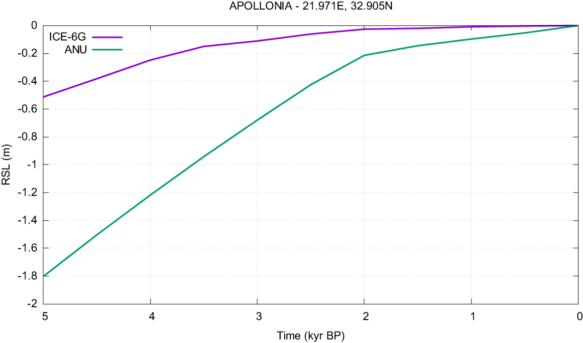


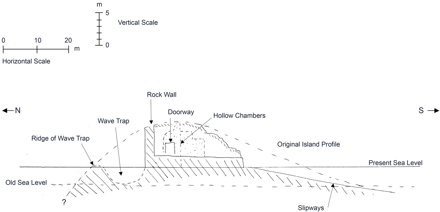


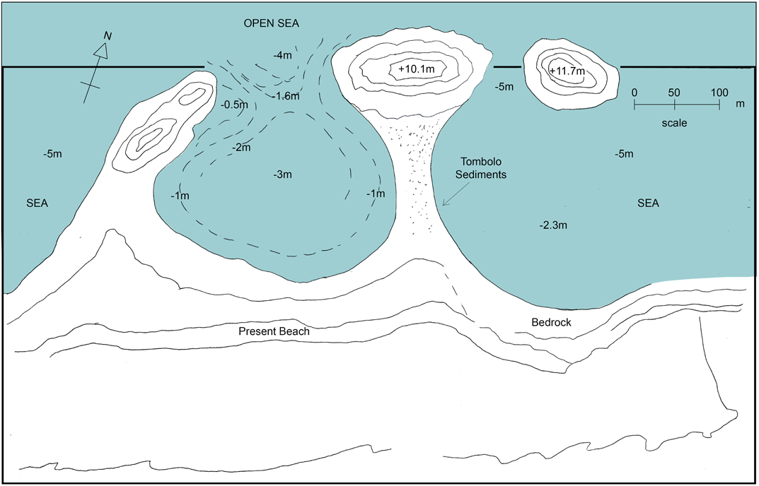

 Open access

