1. Introduction
1.1. Context
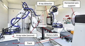
Integration of industrial robots in machining, assembly, and control processes increased for decades. In aeronautics and naval industries, high dimension parts are plentiful and need to be controlled. Nondestructive testing (NDT) methods are used to control material health. X-ray computed tomography (XCT) is a NDT volumetric control method that consists of the 3D reconstruction of the controlled object. Inspection enables the detection of volumetric defects, such as porosity and inclusions. Quality of reconstructed volume depends on a precise knowledge of position and orientation of X-ray emission point and X-ray detector. Existing tomography platforms [Reference Holub, Brunner and Schön1] have generally fixed robot(s) holding either source and detector or the controlled object [Reference Landstorfer, Hiller and Herbst2] to acquire the radiographs of the object used for reconstruction. In the scope of high dimensions part control, a good accessibility to the part is necessary. The ELIXIR platform (CEA-Tech) answers this issue by using two industrial 6-axes robots ABB IRB4600 [3] mounted on 5-m long tracks, each holding a X-ray tube and a X-ray detector (Fig. 1). Additionally, one vertical and one horizontal rotation axis table can be used to position and to rotate the object. As X-ray equipments are mounted on the robot wrist, their position depends directly on the positioning performances of the robots and their environment stability.
Robotised X-ray imaging platform ELIXIR.

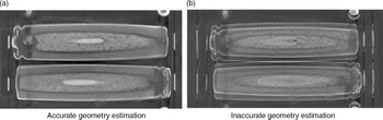
The resolution (voxel size) of reconstructed volumes can reach submillimeter dimensions. To this end, the quality of reconstruction depends on good knowledge of the geometry, which is defined as the position of the source and the position and orientation of the detector. An inaccurate estimation of the real geometry can lead to artifacts in the reconstruction (Fig. 2).
Cross-sections of two rangefinder reconstructed volumes: with an accurate and erroneous geometry knowledge.

1.2. Robotised XCT studies
The simulation of the influence of positioning errors on the quality of reconstruction for circular tomography is a topic of research [Reference Landstorfer, Hiller and Herbst2, Reference Kang, Probst, Slaets and Dewulf4, Reference Kang, Probst, Slaets and Dewulf5]. The usual configuration for a standard configuration is the following: the X-ray tube (source) and the X-ray detector are fixed and the inspected part rotates around an axis. This configuration, the most accurate, is usually named circular tomography. An alternative is to fix the object and to rotate simultaneously source and detector around the part.
Kang et al. [Reference Kang, Probst, Slaets and Dewulf4] measured TCP positioning errors for a two-robots system, each holding the source or the detector, on a circular trajectory tomography. They integrated the positioning errors in the geometry of a tomography simulation of a steel balls device (phantom). Reconstruction quality criteria focus on sphere-to-sphere distances, sphericity errors, and radius errors. For a 0.116 mm voxel size, reconstruction of the spheres is affected with positioning and orientation errors up to 1.0 mm and 1.0°. This study shows that positioning errors directly affect the reconstructed volume. Positioning errors are more critical for nonstandard tomography which require source and detector displacements. Experiments could be performed to confirm simulation results. Kang et al. [Reference Kang, Probst, Slaets and Dewulf5] used a modified reconstruction method based on the Feldkamp−Davis−Kress (FDK) algorithm. This software-based method of Ametova et al. [Reference Ametova, Ferrucci, Chilingaryan and Dewulf6] enables to compensate detector and source misalignments. Firstly, results show that repeatability error has a low effect on the quality of reconstruction compared to accuracy error. Secondly, the modified-FDK method reduced the errors of reconstruction. Landstorfer et al. [Reference Landstorfer, Hiller and Herbst2] performed a noticeably identical study on different objects. After robot positioning performances measurement using laser-interferometer, they simulated circular tomography where source and detector are fixed and robot is used to rotate the object circularly. Deviations from positioning errors are inputted to the geometry with different scales (unidirectional repeatability, multidirectional repeatability, accuracy, total errors). Results show that unidirectional repeatability error (0.025 mm) affects lightly the quality of the reconstructed volume, whereas inputting the accuracy error (0.44 mm) modifies significantly the object shape.
All studies described above point out the straight impact of robot positioning errors on the quality of tomography. However, these studies are concentrated on standard tomography such as circular trajectory tomography. As shown previously, this kind of tomography is well mastered using an accurate rotation table and fixing source and detector positions. Moreover, these articles are exclusively simulation studies. In addition to the robotization of XCT system, nonconventional tomography methods emerge and are aligned on the part size. Helical tomography [Reference Banjak7] or limited view angle [Reference Kisner, Haneda, Bouman, Skatter, Kourinny and Bedford8] need a robotic system to place X-ray tube and detector on both sides of the inspected object. Based on the acquisition of a large number of radiographs, the tomography process could last several hours and the question of nonpermanent physical state of the robots is a topic of interest.
In this scope, the purpose of this article is to measure the influence of robot self-heating on the positioning performances. Thermal drift could skew the knowledge of the geometry and then affect the reconstruction, especially in nonstandard tomography which can need displacements of source and detector for longer acquisition times.
Following section reviews, the robot positioning error sources and focuses on thermal and backlash aspects.
2. Review
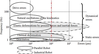
Literature points out phenomena leading to positioning error sources [Reference Robin, Sabourin and Gogu9, Reference Garnier, Subrin and Waiyagan10], listed below (Fig. 3):
Summary of robot positioning error sources [Reference Garnier, Subrin and Waiyagan10].

-
• Geometrical/kinematic errors consist of incorrect estimation of links length and joints offset. Calibration methods have been developed and implemented to improve the identification of kinematic parameters [Reference Wu, Klimchik, Caro, Furet and Pashkevich11].
-
• Elasticity and compliance errors are based on the compliance of joints and links. Studies using elasto-kinematic models calibrate the robot elasticity integrating torsional springs. This kind of error is more critical for large dimension robots, and especially in machining applications owing to external forces and torques. In addition, gaps in gears are responsible for backlash which brings significant errors [Reference Kamali, Joubair, Bonev and Bigras12, Reference Nubiola and Bonev13].
-
• Environment errors such as thermal drift are caused by robot environment properties [Reference Heisel, Richter and Wurst14].
-
• Computational and measurement errors are the consequences of resolution and nonlinearity of the sensors (joint angle) and numerical rounding [Reference Karan and Vukobratović15].
In the scope of robotized XCT, thermal drifts and backlash issues lead to positioning errors. A review of both phenomena follows.
2.1. Thermal drift
Thermal drift is defined as an additional positioning error caused by the thermal expansion of robot links and actuators. The expansion is inducted by thermal heating generated either from the robot self-heating or an environment temperature change. Self-heating of the robot is the consequence of the motors energy dissipation and joint friction.
Poonyapak et al. [Reference Poonyapak, Hayes and McDill16] studied thermomechanical behavior of a simple system using one link and one motor. Stable and dynamic states are both simulated (analytical and finite-element analysis) and experimented to correlate model deformations and experimental values. Model errors reach 3.5%. Heisel et al. [Reference Heisel, Richter and Wurst14] studied the positioning performances on a six-axes robot under ambient temperature changes (heating and cooling phases), and modeled the thermal gradient as an angular joint change in the second axis about 0.0006
 $^{\circ }/K$
determined at different temperature. Reinhart et al. [Reference Reinhart, Gräser and Klingel17] measured position deviations during load and cooling phase, assuming that the errors are thermally induced. An online compensation algorithm is developed by measuring position deviations and recalculating joint offsets and link lengths to minimize the position error. The method reduced the deviation from a maximum of 0.6 to 0.25 mm. However, the effectiveness of the method is limited. The new calculated parameters are only valid for the current configuration and the computational time (about 40 s) is significant for an online method. Leitner et al. [Reference Leitner18] studied the thermal influence of motor heating on positioning repeatability at several speeds. Temperature increase and expansion of the links are clearly related. Linear thermal expansion of links 2 and 3 is considered and compared to measure by a laser, with respectively, 13% and 79% differences between measured and calculated expansions. Gong et al. [Reference Gong, Yuan and Ni19] split error sources into three categories: geometrical, compliance, and thermal. They set up a synthetic model integrating parameters for each error source. Geometrical and compliance errors are identified first in a stable thermal state. Temperature is measured on each link and thermal parameters are determined under robot warm up and cool down phases measurement. After geometrical and compliance calibration, the thermal model reduces residual errors from 0.1−0.3 mm to 0.08−0.11 mm. Eastwood et al. [Reference Eastwood and Webb20] proposed a similar method for a hybrid parallel kinematic machine. After thermal compensation using thermosensors, residual errors are reduced from 0.2 to 0.03 mm (84%). Li et al. [Reference Li and Zhao21] established a dynamic error compensation method based on a thermal model. Both environment temperature changes and self-heating of the robot are studied experimentally using laser tracker and are simulated with finite-element analysis. Experiments about the effect of each motor activation on thermal distribution are performed to identify the axes which are influenced by motors heating. Then, a dynamic compensation method is developed. Real-time laser tracker measurement is used to measure position error. When an error is superior to 0.1 mm (classified as the repeatability of the robot), kinematic parameters are adjusted to minimize the error. The limit is clearly the necessity to calibrate during the process. Mohnke et al. [Reference Mohnke, Reinkober and Uhlmann22] tested three constructive methods to reduce thermal influences by integrating heat supply (to speed up thermal stable state of the robot), cooling system, and thermal decoupling (isolating heat sources such as motors from the system). The study showed that the most effective system is the heat supply with 78% improvement.
2.2. Backlash
Backlash has become a topic of interest since its effect on robot performances is significant, especially on bidirectional positioning accuracy. Practically, backlash corresponds to gaps between gears teeth. Gravity with a substantial lever arm leads to significant torques in motor gears. According to torque direction, the gap is on one side or the other side of the teeth, which induces different joint angles for identical programed positions.
Slamani et al. [Reference Slamani and Bonev23] characterize the gear transmission errors of an industrial robot using laser interferometer. The measurement is performed along a linear path requiring axis 1, 2, and 3. Backlash errors up to 143 µm are clearly determined according to joint angle, for static and dynamic states. Thus, substantial differences between unidirectional and bidirectional repeatability are measured. Slamani et al. [Reference Slamani, Nubiola and Bonev24] modeled the backlash effect with a statistical method. On the linear trajectory, backlash errors (up to 134 µm) are empirically modeled using polynomial functions. Degree of the polynomials is determined with lack-of-fit test. Auxiliary variable is added to fit measurements at several TCP speeds and loads. Model is unfortunately efficient for the used trajectory, corresponding to specific robot configurations. Ming et al. [Reference Ming, Kajitani, Kanamori and Ishikawa25] elaborated a method to determine gear transmission errors of a two-gears systems with input and output shafts, in both clockwise and counterclockwise directions. Backlash is measured as a nonlinear function of output gear angle. Vocetka et al. [Reference Vocetka, Huňady, Hagara, Bobovský, Kot and Krys26] study the influence of approach direction on the positioning repeatability of an industrial robot. After unsuccessful qualification using joint angle encoder measurements, vision images (Digital Image Correlation) are used to measure positioning errors. Significant differences in repeatability are observed according to the direction approach from 0.01 to 0.1 mm.
Backlash and bidirectional repeatability are studied as well in the scope of an XCT application.
2.3. Summary
State of the art shows that both issues have been studied. In the scope of a robotized XCT application, the position of source and detector does not need to be equal to the programed one, but the positioning errors have to be known precisely. A model of the robot behavior is needed to predict positioning drifts. The resolution of seeking defects requires a precise knowledge of the geometry below 100 µm.
The novelty of this article is a corrective method based on the compensation of the thermal drift and the backlash effect using a thermo-geometrical model.
The paper is structured as follows. After a presentation of the experimental setup, position and thermal drift are analyzed. Then, a thermo-geometrical model including backlash compensation is determined. Finally, improvement of positioning performances using the model is presented.
3. Experimental setup
3.1. Accuracy and repeatability: definition
According to ISO 9283-1998 [27], positioning accuracy
 $p_i$
is defined as the difference between the programed
 $\mathbf{X_i^p}$
and the actual measured
 $\mathbf{X_i^m}$
position :
 \begin{align} p_i = \left\| \mathbf{X_i^m - X_i^p} \right\| \end{align}
Repeatability is defined as the maximal positioning error. In practical terms, it is determined by the scattering of positioning through multiple repetitions. Unidirectional repeatability is defined as the repeatability of positioning from a single approach and bidirectional repeatability as the repeatability of positioning from two opposite directions, named as forwards and backwards paths.
3.2. Trajectory description
The trajectory consists of a linear path characterized by stretching and folding back the arm of the robot. The properties of the trajectory are described below :
-
• linear path along x-axis, with clamped track
-
• 24 forwards and backwards positions
-
• 200 repetitions at
 $v = 500 \; \textrm{mm/s}$
, which is representative of nonstandard XCT trajectory
-
• A 2 s stop at every position

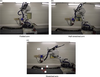
This trajectory could be assumed to a robotized tomography acquisition trajectory. Distances between positions and speeds have been amplified to study the physical state of the robot through a long acquisition. From the trajectory, three configurations are called as: folded arm, half-stretched arm, and stretched arm. It corresponds to the robotic configuration during the trajectory (Fig. 4).
Linear trajectory along x-axis: arm stretching and folding.

To measure positioning performances, a laser-tracker Radian [28] is used with a spherically mounted retroreflector which is magnetically fixed to the end-effector of the robot and defined as the actual tool center point (TCP). It enables the measurement of a point in the laser-tracker frame. Using three known targets located in the robotic cell, the TCP position can be determined in the reference frame, in which the positions are programed. The TCP position is measured continuously with an acquisition frequency of 100 Hz, with a measurement tolerance below 0.01 mm. In addition, an infrared camera Flir A300 controls temperature distribution onto the robot frame. Environment temperature is maintained stable by air conditioning system.
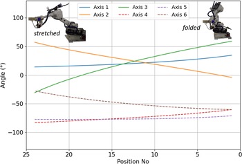
The robot trajectory mainly uses axes 2 and 3 (Fig. 5). Axes 2 and 3 angular variations are, respectively, about 64.2° and 92.3°.
Joint angles evolution as a function of positions along the trajectory: axis 1 to 3 (solid line) and wrist/axis 4−6 (dashed line).

4. Measurement
4.1. Positioning measurement
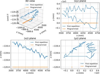
The TCP position in the reference frame is measured. The first repetition is displayed and compared to programed positions (Fig. 6). Differences between measured and programed positions are observed highlighting a geometrical calibration issue. An other statement is the gap between forwards and backwards paths.
Comparison between first repetition measurement and programed trajectory: 3D view and Cartesian projections.

Positioning is analyzed through the 200 repetitions. Cartesian coordinates positions are moved to cylindrical coordinates
 $(r,\theta,z)$
as follows:
 \begin{equation} \left \{ \begin{array}{l@{\quad}l@{\quad}l} r &= &\sqrt{(x-x_0)^2+(y-y_0)^2} \\[4pt] \theta &= &\arctan \left (\dfrac{y-y_0}{x-x_0}\right ) \\[4pt] z &= &z-z_0 \end{array} \right. \end{equation}
With
 $(x_0,y_0,z_0)$
the coordinates of the base origin.
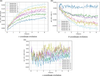
Figure 7 shows the evolution of cylindrical coordinates through the 6.5-h duration of the test for several positions. Positions No. 1−5, 11−14, 21−24 (Fig. 5) correspond to, respectively, folded arm, half-stretched, and stretched configurations. A drift of
 $r$
coordinate is noticeable for every positions and is more substantial for a stretched arm configuration (up to 0.16 mm) than for a folded arm configuration (0.05 mm). A trend evolution of
 $\theta$
coordinate is also noticeable, whereas
 $z$
coordinate has no significant trend.
Evolution of cylindrical coordinates during test.

Curves of
 $r$
and
 $\theta$
coordinates can be fitted by a decay-exponential function describing the Newton’s cooling law about heat transfer [Reference Davidzon29] :
 \begin{equation} f(t) = A (1-e^{-Bt}) \end{equation}
Time constants
 $\tau = \dfrac{1}{B}$
are measured between 2 and 3 h, which means that positioning stabilizes after 4−6 h (
 $3\tau$
).
These positioning drifts can be caused by thermal expansion of the robot links.
4.2. Thermal evolution
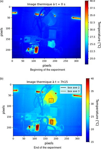
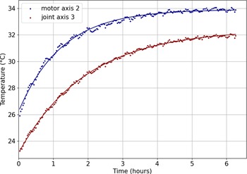
In order to compare thermal evolution with the positioning performances, thermal measurement of the robot structure is performed. Thermal distribution at the beginning and at the end of the experiment is shown in Fig. 8. Thermal images highlight the significant temperature increase, especially on the joint of axis 3 and the motor of axis 2. The temperatures are averaged on the two black rectangles surfaces (Fig. 9). Both curves can be fitted by a decay-exponential function (Eq. 3).
Thermal distribution of the robot frame at the beginning and the end of the experiment.

Evolution of the temperature of the axis 3 joint and axis 2 motor during the repetitions of the trajectory.

This measurement shows a gradient up to 9°C on the robot frame, which means higher gradients in the structure, and likely thermal expansions of the robot links. Moreover, time constants
 $\tau$
are measured at 1.4 and 2.3 h, which means that surface temperature stabilizes between 4.2 and 6.9 h (3
 $\tau$
). These values are close to positioning drift time constants, which can correlate the positioning drifts and the thermal gradient. A parameter is measured at 9.2 and 7.5°C, respectively, for joint axis 3 and motor axis 2. Considering this, the increase of temperature can induce deformations of the links, and hence, modify TCP positioning.
To confirm this hypothesis, a thermo-geometrical model will be defined later on.
4.3. Bidirectional positioning
Figure 6 highlights the gap between forwards and backwards paths, especially in the
 $(xy)$
plane, whose perpendicular vector corresponds theoretically to joint axis 1. Gap is measured up to 0.5 mm which is substantial in the context of robot positioning. As backlash is affected by a torque resulting in gravity force and lever arm, the bidirectional gap
 $\Delta ^{\uparrow \downarrow }$
between forwards and backwards path is determined by :
 \begin{equation} \Delta ^{\uparrow \downarrow } = \| \mathbf{X^\uparrow } - \mathbf{X^\downarrow } \| \end{equation}
Backlash deteriorates more the bidirectional accuracy for stretched arm configurations -
 $x \approx 4700 \; mm$
(Fig. 6). Knowing that the resulting torque at the base of axis 1 is a function of the gravity force and the lever arm, the bidirectional gap can be observed as a function of lever arm
 $l$
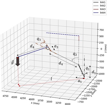
(Fig. 10) which is a trigonometric function of link lengths and joint angles :
 \begin{equation} l = a_1 + d_2 \sin (q_2) + a_3 \sin (q_2+q_3) + d_4 \cos (q_2+q_3) \end{equation}
With
 $a_1, d_2, a_3, d_4$
the lengths parameters of link 1−4, and
 $q_2,q_3$
the joint angles of axes 2 and 3.
Model of lever arm as a function of link lengths
 $d_2$
and
 $d_4$
and joint angles of axis 2
 $q_2$
and axis 3
 $q_3$
.

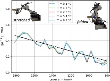
Bidirectional gap as a function of lever arm at different repetitions corresponding to temperature increase.

Lever arm is computed for the 24 positions along the trajectory.
Bidirectional gap is displayed at different repetitions corresponding to different temperatures. Firstly, there is no significant difference between the repetitions, meaning that self-heating of the robot does not impact the backlash effect (Fig. 11). Secondly, the bidirectional gap can be fitted as a linear function of lever arm, including joint angles 2 and 3 (joint angle of axis 1 has no impact on the lever arm), such as:
 \begin{align} \Delta ^{\uparrow \downarrow } &= m l + b \end{align}
From Eqs. (5) and (6), bidirectional gap is expressed as follows:
 \begin{equation} \Delta ^{\uparrow \downarrow } = m (a_1 + d_2 \sin (q_2) + a_3 \sin (q_2+q_3) + d_4 \cos (q_2+q_3)) + b \end{equation}
From Eq. (7) and Fig. 11, the line angle
 $\eta$
is determined using the following:
 $\eta = \arctan (m) = 0.018^{\circ }$
.
Measurement pointed that backlash and thermal drift affect robot positioning performance such as repeatability and bidirectional accuracy. It has been shown that robot self-heating does not modify the backlash effect. Therefore, both phenomena can be modeled independently in an unified thermo-geometrical model which is described herein below.
5. Model
5.1. Geometrical model
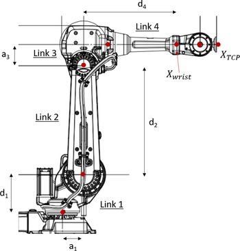
A thermo-geometrical model is defined to simulate the robot behavior. A Modified Denavit-Hartenberg (DHm) [Reference Denavit and Hartenberg30, Reference Hayati and Mirmirani31] model is used to describe the IRB4600 geometry (Fig. 12). TCP position and orientation are determined using homogeneous transformation matrix
 $^0T_{TCP}$
in the base frame
 $\mathcal{F}_0$
:
 \begin{equation} {^0T_{TCP}} ={^0T_1}{^1T_2}{^2T_3}{^3T_4}{^4T_5}{^5T_6}{^6T_{TCP}} \end{equation}
Drawing of the robot for zero joint angles.

With, for non consecutive parallel axis, the homogeneous transformation matrix
 $^{i-1}T_i$
:
 \begin{equation} {^{i-1}T_i} = Rot(\mathbf{z_{i-1}},\theta _i) \, Tr(\mathbf{z_{i-1}},d_i) \, Tr(\mathbf{x_i},a_i) \, Rot(\mathbf{x_i},\alpha _i) \end{equation}
And for consecutive near parallel axis [Reference Hayati and Mirmirani31]:
 \begin{equation}{^{i-1}T_i} = Rot(\mathbf{z_{i-1}},\theta _i) \, Tr(\mathbf{z_{i-1}},d_i) \, Rot(\mathbf{x'_i},\alpha _i) \, Rot(\mathbf{y''_i},\beta _i) \end{equation}
With
 $\theta _i$
,
 $d_i$
,
 $a_i$
,
 $\alpha _i$
, and
 $\beta _i$
the DHm parameters from frame
 $\mathcal{F}_{i-1}$
to
 $\mathcal{F}_i$
.
Then, the TCP position
 $\mathbf{X_{TCP}}$
is contained in the TCP homogeneous transformation matrix
 $^0T_{TCP}$
, defined by a nonlinear function, using Eq. (8):
 \begin{equation} ^0T_{TCP} = f(\mathbf{p},\mathbf{q}) \end{equation}
Where
 $\mathbf{p}$
contains the DHm parameters and
 $\mathbf{q}$
the joint angles.
5.2. Thermal model
The thermal model is based on the thermal expansion of the robot links using a temperature gradient defined by Eq. (3). Assuming a homogeneous temperature distribution and using steel linear expansion coefficient
 $\gamma _{steel} = 16e^{-6}$
[32], lengths parameters
 $a_i$
and
 $d_i$
of the DHm model are defined by:
 \begin{align} a_i (t) &= a_i(0) (1+ k A (1-e^{-Bt})) \end{align}
 \begin{align} d_i (t) &= d_i(0) (1+ k A (1-e^{-Bt})) \end{align}
With
 $A$
and
 $B$
are the fitted parameters of the temperature increase (Section 4.2) and
 $k$
a coefficient which is proportional to
 $\gamma _{steel}$
.
The resulting TCP position
 $\mathbf{X_{TCP}}(t)$
is determined by an update of Eq. (11):
 \begin{equation} ^0T_{TCP}(t) = f(\mathbf{p}(t),\mathbf{q}) \end{equation}
A study of TCP positioning drift regarding the thermal expansion axis by axis has been performed showing that thermal expansion of links 2 and 4 are the most impacting. It is intuitive as both links are the longest ones. As link 3 is between links 2 and 4, its thermal expansion is considered as well. Based on these statements, the following study will be made at the center of the wrist, considering a three revolute joints model with four links. Thus, the position of the wrist center
 $\mathbf{X_{wrist}}$
which is contained in the transformation matrix
 $^0T_4$
is computed using parameters of links 1 to 4 and joint angles :
 \begin{equation} ^0T_4(t) ={^0T_1(\mathbf{p_1(t)},q_1)} \,{^1T_2(\mathbf{p_2(t)},q_2)} \,{^2T_3(\mathbf{p_3(t)},q_3)} \, ^3T_4(\mathbf{p_4(t)},q_4) \end{equation}
Such as:
 \begin{equation} ^0T_4(t) = \begin{bmatrix} \mathbf{R_{wrist}} & \mathbf{X_{wrist}} \\ 0 & 1 \end{bmatrix} \end{equation}
With
 $^iT_{i+1}$
the homogeneous matrix transformation determined using Eq. (9),
 $\mathbf{p_i(t)}$
the DHm parameters of axis
 $i$
,
 $q_i$
the joint angle of axis
 $i$
and
 $d_4(t)$
the length of link 4 (Fig. 12).
As the assumptions take into consideration only thermal expansion of links 1 to 4, the TCP position
 $\mathbf{X_{TCP}}$
is computed using homogeneous transformation matrix from axis 4 (wrist) to tool (Eq. 8):
 \begin{equation} {^0T_{TCP}}(t) ={^0 T_{4}}(t) \,{^{4} T_{TCP}} = \begin{bmatrix} \mathbf{R_{TCP}} & \mathbf{X_{TCP}} \\ 0 & 1 \end{bmatrix} \end{equation}
5.3. Backlash model
A positioning gap between forwards and backwards paths highlighted the backlash phenomenon. Backlash affects positioning when the direction of the torque applied in the teeth changes. For axes 2−6, there is no direction change of the torque, which means that backlash can only occur in the joint axis 1. This gap in gears transmission is compensated by a joint angle offset. Consequently, the backwards joint angle
 $q_1^\downarrow$
is expressed as a function of the forwards position joint angle
 $q_1^\uparrow$
and the backwards position joint angle offset
 $\Delta q_1$
:
 \begin{equation} q_1^\downarrow = q_1^\uparrow - \Delta q_1 \end{equation}
Updated joint angle is inputed in Eq. (15) to compute compensated backwards positions path.
6. Model calibration
In order to compare the measurement and the model, TCP measured positions
 $\mathbf{X^{mes}_{TCP}} = (x^{mes},y^{mes},z^{mes})^T$
are moved to the center of the robot wrist
 $\mathbf{X^{mes}_{wrist}}$
using Eqs. (8), (16), (17):
 \begin{equation} {}^{0}T_{4} = {}^{0}T_{TCP}{}^{TCP}T_{6}{}^{6}T_{5}{}^{5}T_{4} \end{equation}
6.1. Geometrical calibration
Firstly, geometrical calibration of the DHm parameters is computed based on the first repetition of the trajectory, using nonlinear optimization algorithm. Minimization of cost function
 $g$
which is the residuals sum between measures and model is performed with a sequential least-squares programming method [33] with:
 \begin{equation} g(\mathbf{p}) = \sum \limits _{i=0}^N \left \| \mathbf{X^{mes}_i} - \mathbf{X^{mod}_i} (\mathbf{p}) \right \| \end{equation}
Optimized vector of DHm parameters
 $\mathbf{p_{opt}}$
is used to compute
 $\mathbf{X^{mod}}$
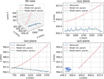
. Figure 13 shows Cartesian projections of the measured positions and the initial and optimized DHm parameters model. Initial parameters [3] positions do not fit suitably to the measured positions, whereas optimized parameters positions fit correctly. The mean residuals are improved from 1.39 to 0.06 mm/position attesting the goodness-of-fit of the optimized parameters, describing the positioning at a cold state (ambient temperature, about 20
 $^{\circ }$
C).
First repetition of measured positions compared with initial and optimized DHm parameters model: 3D view and Cartesian projections.

6.2. Thermal calibration
These parameters are used for the thermo-geometrical model. As mentioned previously, only links 2, 3, and 4 thermal expansion is simulated. Figure 14 displays the evolution of cylindrical coordinates of measured and model positions at the base of the robot wrist through the 200 repetitions. The thermal model (Section 5.2) fits well the measured drifts, especially on the
 $r$
and
 $\theta$
coordinates. It confirms that the observed drift is mainly caused by the robot self-heating which induces thermal expansions of links 2, 3, and 4.
Evolution of cylindrical coordinates of measured and model positions in the course of the test for several robotic configurations, with
 $k = 0.80$
(Eq. 12).

6.3. Backlash calibration
Backlash joint angle offset is determined to fit backwards and forwards paths with function optimization. Minimization of objective function
 $f_{obj}$
consisting of residuals between measurement and model is performed with
 $\Delta q_1$
optimization :
 \begin{equation} f_{obj}(\Delta q_1) = \sum _{i=1}^{N} \mathbf{X_{i}^{mes}} - \mathbf{X_{i}^{mod}}(\mathbf{q},\Delta q_1) \end{equation}
The input backlash joint angle offset corresponds to the fitted line angle 0.018
 $^{\circ }$
(Section 4.3). Resulting
 $\Delta q_1$
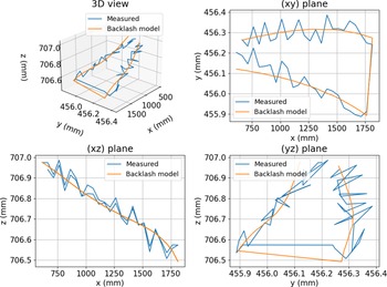
fits the minimum gap between model and measurement. Results are displayed in Fig. 15 and show goodness-of-fit of the model with measured positions for backlash joint angle offset
 $\Delta q_1 = 0.013^{\circ }$
.
Comparison of measured position of backwards and forwards paths with the backlash model for a backlash joint angle offset
 $\Delta q_1 = 0.013 ^\circ$
.

7. Positioning performances
7.1. Thermo-geometrical compensation
In order to evaluate the pertinence of the thermal model, positioning performances are compared before and after the compensation of the measured positions with the developed model. Compensated positions
 $\mathbf{X^{comp}}$
are determined using:
 \begin{equation} \mathbf{X^{comp}_{i,j}} = \mathbf{X^{mes}_{i,j}} - \left ( \mathbf{X^{mod}_{i,j}} - \mathbf{X^{mod}_{i,0}} \right ) \end{equation}
For every positions, forwards and backwards, the mean position
 $\mathbf{\overline{X^{mes}_i}} = \sum \limits _{j=0}^N \mathbf{X^{mes}_{i,j}}$
is computed over the
 $N$
repetitions and used to determine the mean accuracy
 $\overline{\Delta _i}$
:
 \begin{equation*} \overline {\Delta _i} = \left \| \mathbf {\overline {X^{mes}_i}} - \mathbf {X^{prog}_i} \right \| \end{equation*}
To measure positioning scattering over the
 $N$
repetitions, the maximum distance to the mean position
 $r_i$
is computed using the following:
 \begin{equation} r_i = \max \limits _{j=0}^N \left \| \mathbf{X^{mes}_{i,j}} - \mathbf{\overline{X^{mes}_i}} \right \| \end{equation}
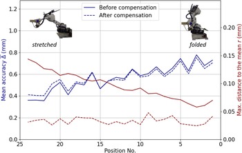
These values are computed with the raw positions from the measurement. Figure 16 displays the mean accuracy and the maximum distance to the mean position for the uncompensated and model compensated positions for the forwards path. First, the mean accuracy is rationally not affected by the thermal model compensation, and is measured between 0.4 and 0.8 mm. The uncompensated positioning scattering is about 0.06 (folded) and 0.15 mm (stretched), depending on the position. The thermal model compensation steeply reduces the positioning scattering, hence increasing the positioning repeatability by a factor of 1.7−5.8. The compensated positioning scattering is approximately equal for every position and about 0.04 mm, which is close to the robot unidirectional repeatability.
Mean accuracy and maximum distance to the mean position for the forwards path with uncompensated and compensated positions model.

7.2. Backlash compensation
As backlash model computes backwards position
 $\mathbf{X^{\downarrow }}$
with joint angle offset of axis 1, the efficiency on bidirectional accuracy is determined comparing mean error with uncompensated backwards position
 $err_{unc}$
and compensated backwards position
 $err_{comp}$
:
 \begin{align} err_{unc} &= \dfrac{1}{N} \sum \limits _{i=0}^N \left \| \mathbf{X^{mes}_i} - \mathbf{X^{mod,unc}_i} \right \| \nonumber \\ err_{comp} &= \dfrac{1}{N} \sum \limits _{i=0}^N \left \| \mathbf{X^{mes}_i} - \mathbf{X^{mod,comp}_i} \right \| \end{align}
Backlash compensation significantly reduces the bidirectional mean error from 1.533 to 0.069 mm.
In order to verify the quality of the backlash compensation model, four additional experiments on the same trajectory have been made. Three experiments have been performed at the same speed
 $v = 500 \; mm/s$
, and one at
 $v = 20 \; mm/s$
. First repetition (cold state) of the trajectories is used to measure the quality of backlash compensation model. The backlash joint angle offset
 $\Delta q_1 = 0.013 ^{\circ }$
has been input in the calibrated geometrical DHm model for every trajectory. The residual error between measurement and model is computed. Results are summarized in Table I, highlighting the performance of the backlash compensation for all trajectories and steeply reducing the mean and standard-deviation residual error.
Bidirectional positioning improvement with backlash compensation for
 $\Delta q_1 = 0.013^{\circ }$
.

8. Conclusion and perspectives
Tomography has shown its potential for NDT. Implementing this process for large parts is a real challenge. The article highlights the factors that strongly influence the accuracy of the robots to make the robotic cell able of part reconstruction over long periods of time, highlighting a positioning error due to thermal drifts. The implementation of a representative trajectory of the process, that is, helical tomography, with movements over 6.5 h has highlighted a repeatable positioning error. We have then implemented a thermo-geometrical model with backlash compensation and have shown that the model we proposed is able to respond to the observed phenomena. The main results obtained show that it is possible to preset an accuracy close to the repeatability of the robot, that is, 0.07 mm.
The development of such a robotic cell shows many scientific contributions to come. Indeed, using a kinematically redundant robotic cell allows us to foresee the generation of constrained trajectories. It also appears, in the context of the X-ray tomography process, to have a clear understanding of the positioning of the source with respect to the detector in the reference of the part that is measured, namely geometrical calibration. On this point, the implementation of a device called “geometrical calibration phantom” [Reference Ferrucci, Leach, Giusca, Carmignato and Dewulf34] is therefore under study for this robotic cell to have parts reconstructions without artifacts.
Acknowledgments
This research work is funded by the Conseil Régional des Pays de la Loire.
Competing interests
The authors declare none.
Authors’ contribution
-
• Adrien Le Reun: Conceptualization, Investigation, Methodology, Modelling, Testing, Writing, Editing
-
• Kevin Subrin: Conceptualization, Investigation, Methodology, Reviewing, Editing
-
• Anthony Dubois: Methodology, Testing
-
• Sebastien Garnier: Conceptualization, Investigation, Methodology
Ethical considerations
None.