Introduction
The goal of tissue engineering (TE) is to design, rebuild, and replace damaged or diseased tissue that the body cannot repair unassisted.Reference Langer1 Key to the evolution of TE has been the concept of a scaffold, which is needed to guide and support tissue formation during the repair process.Reference Neufurth, Wang, Schroder, Feng, Diehl-Seifert, Ziebart, Steffen, Wang and Muller2–Reference Zhang, Gupte and Ma8 While there have been early clinical successes using a number of three-dimensional (3D) scaffold strategies (see the Introductory article in this issue),Reference Hollister and Murphy9 scaffold design has continually evolved with technology over the last two decades.Reference Hollister and Murphy9,Reference Evangelatov and Pankov10 The optimal design is highly dependent on the clinical indication and envisioned surgical technique, but 3D printing technologies, including sintering, ablation, extrusion, and photochemical methods, have all shown the potential to transform the regenerative medicine industry and push it into mainstream clinical practice.
Scaffold design, functionality, and chemistry have each been shown to contribute to the regenerative process.Reference Seitz, Rieder, Irsen, Leukers and Tille11 While the ability to design scaffolds morphologicallyReference Dhandayuthapani, Yoshida, Maekawa and Kumaret12 and derivatize them with bioactive groups has evolved,Reference Tang and Becker13 there has been a lag in the development of new polymers and scaffold precursors available to bioengineers to further advance the frontier of 3D printing for medical applications.Reference Li, Cui, Sun, Aifantis, Fan, Feng, Cui and Watari14 The most recent generation of 3D scaffolds for TE typically uses degradable polymers that have been used in devices or formulations for applications approved for use in humans by the US Food and Drug Administration (FDA). Polyesters, polyurethanes, and polylactides have received the most attention in FDA-approved resorbable implant products.Reference Chen, Liang and Thouas15 Each has been used in extrusion-based printing technologies.
However, the diversity of materials has been limited by the industry’s almost extreme aversion to the risk associated with the adoption of new materials and the uncertainty about how custom 3D technologies will be regulated. This aversion to risks has spilled over into the research community where the limitations of the physical, chemical, and biological properties of widely adopted materials have led to shortcomings in both research output and subsequent clinical performance. New materials that have shown promise in the laboratory and pre-clinically include amino acid-based poly(ester urea),Reference Stakleff, Lin, Smith Callahan, Wade, Esterle, Miller, Graham and Becker16 tyrosine-derived polycarbonates,Reference Aamer, Stafford, Richter, Kohn and Becker17 and poly(propylene fumarate) (PPF).Reference Fisher, Holland, Dean, Engel and Mikos18 Each possesses advantages and disadvantages, but failure to populate the innovation pipeline with new materials will continue to hinder their development and use in 3D printing. New materials are needed to enable the generation of highly tailorable and functional scaffolds for TE.
This review highlights the 3D methods currently used to generate scaffolds for TE. We detail some of the key parameters that are considered during the application-specific design process, including porosity and degradation. Finally, we focus on photochemical printing methods and the use of PPF as an example of the properties that would be useful for a clinical tissue regeneration product.
Three-dimensional printing and fabrication technologies
Methods
Traditional scaffold fabrication methods
The external shape of a scaffold can be controlled by casting, which uses a polymer or monomer in a liquid state for easy injection into the mold. This could be chemical casting using heat or light to initiate polymerization in a mold, melt casting, or solvent casting into a mold.Reference Schruben and Gonzalez19,Reference Ebewele20 Light-based casting (i.e., photopolymerization) requires translucent molds.Reference Rajagopal, Chitre and Aras21,Reference Takaichi, Wakabayashi and Igarashi22 The most commonly used method for introducing porosity in polymer scaffolds has been the inclusion of salt crystal porogens.Reference Yoon, Kim and Park23,Reference Joerg, Theresa and Antonios24 Once the cast is formed, it is put in water where the salt crystals are leached out. The highest density of pore space can be used to produce foam.Reference Yoon, Kim and Park23,Reference Joerg, Theresa and Antonios24 Sheet-like structures can be prepared as solids or weaves from fibers, such as in electrospinning.Reference Reneker and Yarin25–Reference Zheng, Xie, Lin, Hua, Yu, Reneker and Becker27
Three-dimensional polymer scaffold printing
The two primary 3D printing modalities are laser sinteringReference Goodridge, Tuck and Hague28 and photocross-linking,Reference Dean, Jonathan, Siblani, Wang, Kim, Mikos and Fisher29 with the latter holding promise for the highest resolution (see the Introductory article in this issue). We review the commonly used 3D printing techniques for preparing polymer scaffolds.
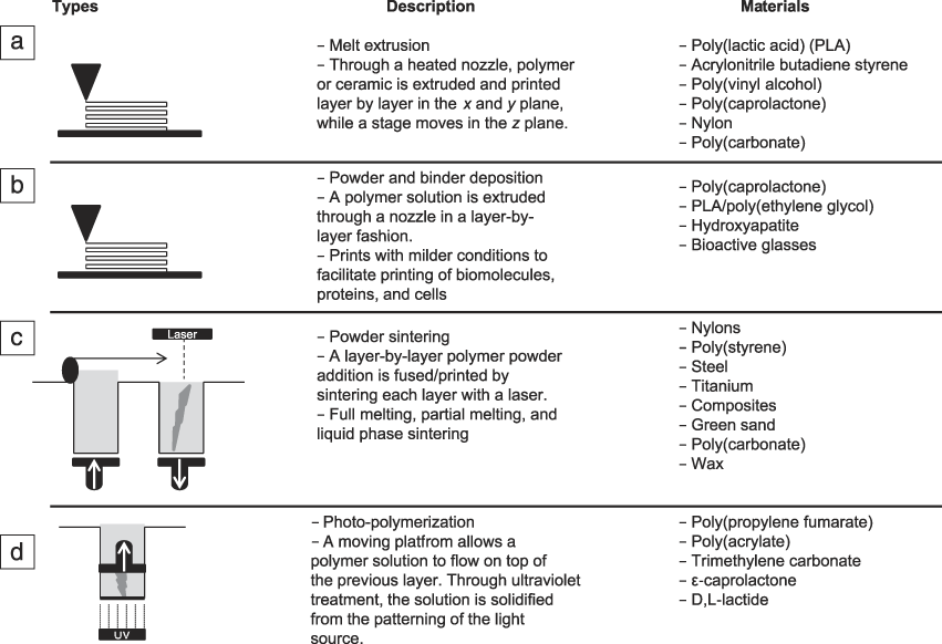
Fused deposition modeling
This method uses a solid polymer feedstock that is fed through a heated nozzle. This has not been done with PPF; however, it has been used with a variety of resorbable polymers (e.g., poly(caprolactone) [PCL], poly(lactic acid), poly(D,L-lactide-co-glycolide)).Reference Farahani, Chizari and Therriault30,Reference Kim, McBride, Tellis, Alvarez-Urena, Song, Dean, Sylvia, Elgendy, Ong and Hollinger31 Resolution is dependent on nozzle diameter (Figure 1a). The resulting geometry is a series of rods layered at varying angles.Reference Ringeisen, Spargo and Wu32 These scaffolds are typically rendered from PCLReference Jensen, Rölfing, Svend Le, Kristiansen, Nygaard, Hokland, Bendtsen, Kassem, Lysdahl and Bünger33 but alternative polymers and metals are surfacing.Reference Masood and Song34
Descriptions of the four main types of three-dimensional (3D) printing techniques. (a) Fused deposition modeling, (b) inkjet/3D plotting, (c) selective laser sintering, and (d) stereolithography.

Inkjet 3D printing and cell printing
The use of inkjet printers (Figure 1b) for polymer 3D printing presents several challenges. One issue is registering multiple layers. One method of inkjet printing is to shoot a liquid into a powder bed of cured polymer.Reference Ju-Yeon, Bogyu, Benjamin and Min35 Another is to mix solvents into a polymer to keep it flowing through the printer nozzle. Sometimes liquid polymers are used as a binder for another material such as a ceramic. The part is then sintered, and the polymer is burned off.Reference Butscher, Bohner, Hofmann, Gauckler and Müller36 Finally, live cells may be added to a polymer that gels but does not cure to a solid, which is a hydrogel. These cell-containing hydrogels are sometimes referred to as bioinks. This process, as a whole, has been referred to as bioprinting. The challenge in bioprinting is to keep the cells alive until the scaffold is placed in a bioreactor or it is implanted.Reference Xu, Zhao, Zhu, Albanna, Yoo and Atala37
Laser sintering
This technology uses two pistons, one to feed powderized polymer, ceramic, or metal, and the other to draw down the part after a laser has melted a layer of powder. Because the part sinks into the powder bed as it is rendered, no support structures are needed (Figure 1c), allowing for complex and high resolution geometries.Reference Goodridge, Tuck and Hague28,Reference Dias, Guedes, Flanagan, Hollister and Fernandes38,Reference Bártolo39 Inert as well as resorbable medical implants prepared in this fashion have been used in the clinic.Reference Probst, Hutmacher, Müller, Machens and Schantz40 Laser-sintered part resolution can be very high, but is generally not as high as the highest resolution seen in photocross-linking 3D printers (see details later in text).
Photocross-linking
The original 3D printing modality is stereolithography (SLA) (Figure 1d). SLA printers use a single-point laser to draw out each layer, line by line.Reference Bártolo39 More recently, photocross-linking 3D printers have used Digital Light Processing (DLP) chips to print an entire layer at once. This allows control of spot-to-spot (lateral) and interlayer (vertical) binding. PPF has been successfully printed with both SLA- and DLP-based 3D printers.Reference Dean, Jonathan, Siblani, Wang, Kim, Mikos and Fisher29
Materials
The recent generation of TE scaffolds centers around potential and clinically relevant degradable polymers. Some of the most widely studied biodegradable polymers include: PPF (Figure 2a), poly(lactic-co-glycolic acid) (Figure 2b), PCL (Figure 2c), poly(L-lactic acid) (Figure 2d), poly(ester urea), polyanhydrides, and poly(ortho esters).Reference Stakleff, Lin, Smith Callahan, Wade, Esterle, Miller, Graham and Becker16,Reference Fisher, Holland, Dean, Engel and Mikos18, Reference Rezwan, Chen, Blaker and Boccaccini41–Reference Benz, Tenbroek and Luo47 The commonality among most of these degradable polymers is the ester bond and FDA approval for certain medical applications. Poly(ethylene glycol) (PEG) (Figure 2e) hydrogels are neither degradable nor contain the ester bond, but they are widely used in a number of TE applications. However, because they are non-resorbable, they will not be discussed further in this review.
The chemical compositions of common degradable biomaterials. (a) Poly(propylene fumarate), (b) poly(lactic-co-glycolic acid), (c) poly(caprolactone), (d) poly(L-lactic acid), and (e) poly(ethylene glycol).

TE literature is dominated by papers examining the importance of mechanical properties in parallel with new healthy tissue growth such as new bone growth. Many of these studies on bone growth are carried out in vitro in two-dimensional (2D) and 3D culturesReference Smith Callahan, Ganios, Childers, Weiner and Beckeret48–Reference Peyton, Kim, Ghajar, Seliktar and Putnam51 or in vivo with small, non-critical size defects.Reference Lewandrowski, Cattaneo, Gresser, Wise, White, Bonassar and Trantolo42 However, degradability may be as important if not more important in the design of TE materials or devices if bone remodeling is to occur during the bone wound healing window. Healing a particular wound, for example a bone wound, may only require three to four months, but materials such as PCL are designed to last a year or more. Thus, there is a disjunction between some resorbable material degradation rates and the need for them to resorb in sync with tissue growth and regeneration.
The focus on restoring function with an implant displaying final mechanical properties may fail to consider the need for surgical reconstruction to heal existing tissue and regenerate and remodel missing tissue.Reference Webb, Yang and Ameer52–Reference Raggatt and Partridge54 The idea of a scaffold and the early infusion of neotissue as a replacement or temporary bridge goes hand in hand with degradability. When natural or synthetic scaffolds are placed in the body, they should be sufficiently strong (i.e., not lose their material properties through degradation) to allow cells to migrate and start producing extracellular matrix so as not to disrupt (i.e., act as a barrier) new tissue growth (i.e., host tissue infusion) and remodeling. In a clinical setting, external casts or internal plates, rods, or wires are used to protect or maintain the integrity of wound site healing and remodeling, so the need for materials providing end-stage mechanical support similar to normal healthy tissue throughout the life of the repair may be unnecessary if not antagonistic to wound healing.
Design elements
Porosity
The creation of TE scaffold designs with internal porous features has evolved from a number of methods, including porogen leaching, gas bubbling, fiber weaving, (e.g., salt leaching, gas foaming, electrospinning), computer-aided design (CAD), and computer-aided manufacturing (e.g., 3D printing). The development of 3D printing methods has many advantages over less precise, non-CAD methods. Three-dimensional printing allows for the precise fabrication of (1) the external shape of a scaffold that fits the shape of a specific defect (i.e., patient-specific implant), and (2) the internal pore geometry that guides host tissue and vasculature infusion of the defect site. The pore architectural design can also facilitate cell seeding and/or nutrient flow for ex vivo bioreactor culturing, and the design of the pore geometry (e.g., materials used, pore wall thickness) can help ensure resorption of the scaffold. All of this is accomplished through geometrical control of the 3D printer following a predetermined CAD file.
Mechanisms and biology of degradation
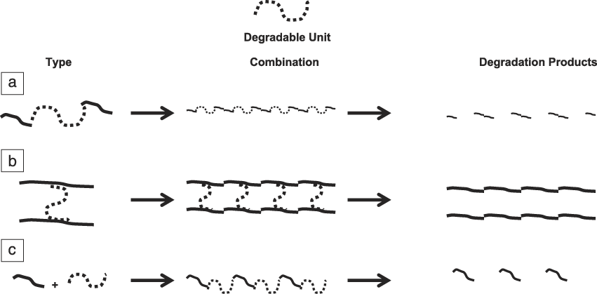
There are many different ways to incorporate synthetic, degradable motifs such as monomer design, degradable cross-links, copolymerization, and post-modifications (Figure 3). Two different types of erosion profiles are typically observed: bulk or surface erosion (Figure 4). As the name suggests, surface erosion describes the degradation and loss of the material only at the surface. The original geometry is generally maintained as the scaffold decreases in size. The rate of degradation in surface erosion is more predictable than in bulk erosion. During bulk erosion, degradation of the polymer occurs homogenously throughout the entire scaffold as a result of swelling and higher uptake of water into the material.Reference Göpferich55,Reference Burkersroda, Schedl and Göpferich56 There may be concerns that bulk erosion will occur too quickly, resulting in a dramatic loss of integrity and a burst release of degradation byproducts at the site of implantation. A rapid accumulation of degradation byproducts may exceed the local environment’s ability to remove or metabolically handle the high concentration of byproducts, a situation that could be harmful to adjacent and/or newly regenerated tissue.
A representation of different degradation motifs where the degradable unit is utilized (a) in the monomer design, (b) the cross-linkage between two chains, or (c) a copolymerization where one chain contains the degradable unit.
(a) A schematic showing the main difference between surface erosion, where the elimination of product only takes place at the surface, and bulk erosion, where the elimination of product happens evenly throughout the entire material. This is contrasted with the degradation of photochemically cross-linked poly(propylene fumarate) (PPF) scaffolds, which show distinctly different mechanical property changes with time. Accurate prediction of the mechanical properties is critical to scaffold design, (b) where the layers are highly interconnected, and the geometric assemblies and struts are unique to (c) three-dimensional (3D)-printed scaffolds.
The system that is currently preferred for wound healing and TE tissue regeneration utilizes surface-eroding materials with extremely long degradation times such as polyesters with degradation half-lives of ∼3.3 years.Reference Göpferich55 As noted previously, long scaffold retention times may not be ideal for new tissue growth. The bulk of available scaffold rendering methodologies have been developed to increase degradation times. Important parameters to understand for degradation profiles are water uptake as a result of swelling and pH changes due to degradation products or the local physiological environment. The process of hydrolysis and the chain scission of the liable bonds in the polymer chains play a major role in the erosion and mass loss of the material (Figure 3). The rate of hydrolysis is related to the amount of swelling and water uptake (i.e., low-swelling polymers typically undergo slow surface erosion). The degradation rate can be affected by the addition of hydrophilic moieties in the monomer unit or copolymerization with quickly degrading polymers such as polyanhydrides that have a half-life of ∼30 min.Reference Göpferich55 The degradation rate profiles and physical changes to the material can be monitored by weight percent change, mass spectrometry, size-exclusion chromatography, and compression testing.
Degradation byproducts are also monitored and characterized for toxicity concerns and pH changes as a result of acid formation. Changes in pH have been shown in some cases to speed up degradation through an autocatalytic process but may be detrimental to bone growth and formation.Reference Burkersroda, Schedl and Göpferich56 The unsaturated polyester PPF breaks down into fumaric acid and propylene glycol. Both of these byproducts are locally metabolized.Reference He, Timmer, Yaszemski, Yasko, Engel and Mikos57 Developing degradable cross-linkable systems that react under a narrow range of light wavelengths in order to sufficiently activate a cross-linking photoinitiator, projected onto the polymer with a small spot size, are usually essential for 3D printing.
Poly(propylene fumarate)
Chemistry
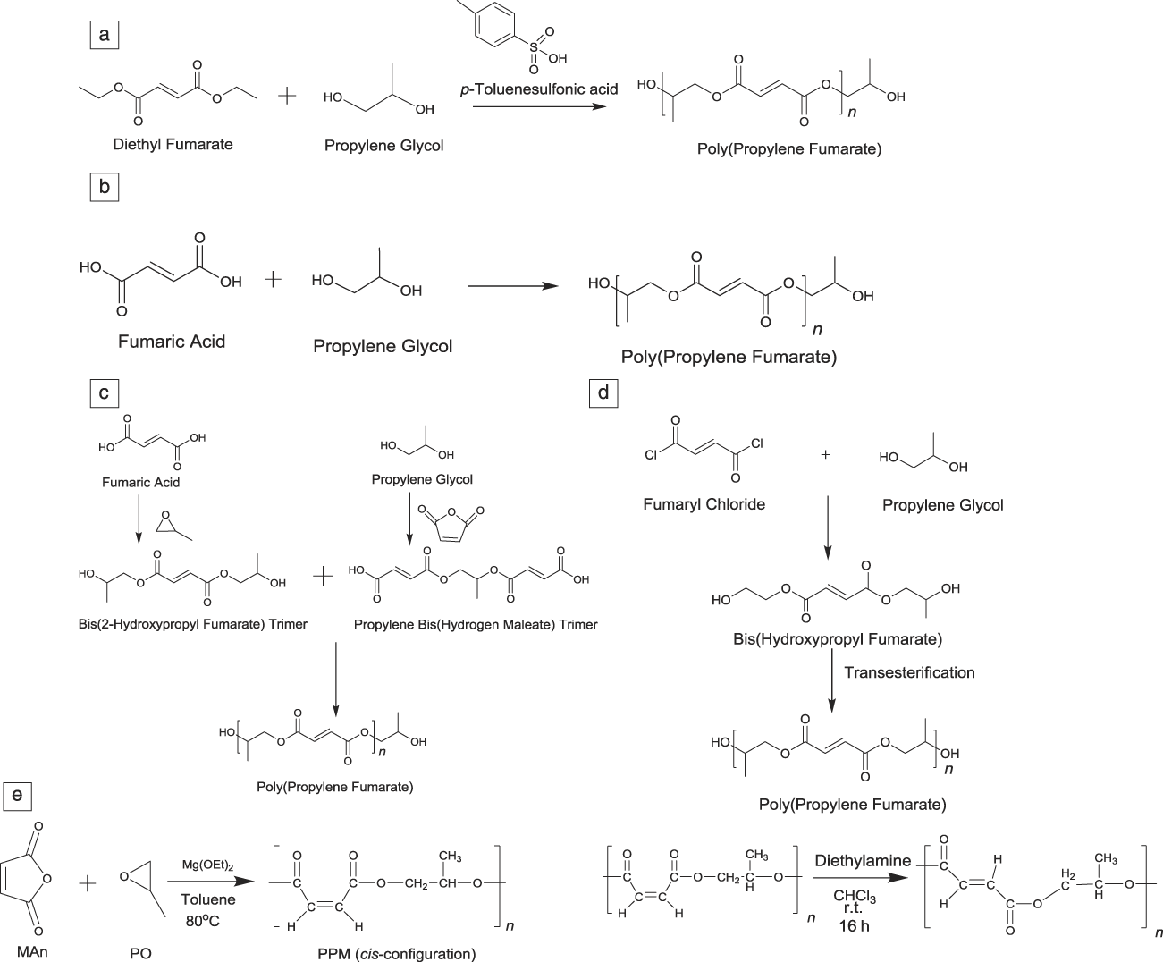
There are a number of synthesis pathways for PPF that result in different polymer properties, including molecular weight (MW) and polydispersity index (PDI = Mw/Mn). Originally, SandersonReference Sanderson58 produced PPF by transesterification of diethyl fumarate and propylene glycol with the catalyst para-toluenesulfonic acid (Figure 5a). The following year, Gerhart and HayesReference Gerhart and Hayes59 prepared PPF through a condensation reaction of propylene glycol and fumaric acid (Figure 5b). Control over MW and PDI is difficult to reproduce. MW in the range of 500–1200 and molecular mass distributions (i.e., PDI) from three to four are typically prepared by that method. Domb prepared PPF through two main reaction methods (Figure 5c).Reference Domb60,Reference Domb, Kost and Wiseman61 The first method included preparing the bis(hydroxypropyl) fumarate trimer and propylene bis(hydrogen maleate) trimer by reacting propylene glycol/fumaric acid and maleic anhydride/propylene glycol, respectively. The two trimers are then reacted to produce PPF. Another method is preparing bis(hydroxypropyl) fumarate trimer at ambient temperature by reacting fumaryl chloride and propylene glycol. The purified trimer is reacted in the presence of the transesterification catalyst antimony trioxide to produce PPF. PPF with MW in the range of 750–1500 and PDI in the range of 1.7–3 were produced by this method.
Ways to synthesize poly(propylene fumarate) by (a) transesterification of diethyl fumarate and propylene glycol with the catalyst p-toluenesulfonic acid,Reference Sanderson58 (b) a condensation reaction of propylene glycol and fumaric acid,Reference Gerhart and Hayes59 and (c) preparation of the bis(hydroxypropyl) fumarate trimer and propylene bis(hydrogen maleate) trimer by reacting propylene glycol/fumaric acid and maleic anhydride/propylene glycol, respectively. The two trimers are then reacted.Reference Domb60,Reference Domb, Kost and Wiseman61 Also, a (d) reaction of fumaryl chloride and propylene glycol to produce bis(hydroxypropyl fumarate) then transesterification with antimony trioxide as a catalyst,Reference Yaszemski, Mikos, Payne and Hayes62,Reference Yaszemski, Payne and Mikos63 and finally (e) polymerization of poly(malic anhydride-co-propylene oxide) and isomerization of poly(malic anhydride-co-propylene oxide).Reference DiCiccio and Coates64
In 1994, Yaszemski et al.62,63 synthesized PPF through an initial reaction of fumaryl chloride and propylene glycol at room temperature to produce bis(hydroxypropyl fumarate), which underwent transesterification under vacuum with antimony trioxide as a catalyst in a nitrogen atmosphere to yield PPF (Figure 5d) with MW in the range of 850–1500 and a molecular mass distribution ranging from 1.6–3. This was accomplished by varying polymerization time from four to 24 h. Traditional methods to synthesize PPF require high energy input, high vacuum, long reaction times, and result in low conversion with uncontrolled molecular mass distribution, conjugate-addition side reactions, and unwanted cross-linking, all of which greatly influence the mechanical properties and degradation rates of the final product.
Recently, Coates and co-workersReference DiCiccio and Coates64 have successfully synthesized PPF with a high MW, narrow PDI below 1.6, and low ether linkage (<1%) using a chain growth mechanism with mild reaction conditions (Figure 5e). In their method, maleate anhydride and epoxide are polymerized through a ring-opening copolymerization with a chromium salen complex as catalyst at 45°C. The resulting poly(propylene maleate) was isomerized using diethylamine at room temperature for 16 hours to yield poly(propylene fumarate). PPF synthesized in this way had a MW of 17 kDa, a molecular mass distribution of 1.6, and less than 1% ether linkage less with 99% conversion. Compared with traditional synthesis methods, the chain growth mechanism provides PPF with better molecular properties (i.e., narrower molecular mass distribution/PDI and well-defined viscosity properties), and the reaction is more reproducible, making it possible to produce PPF with controlled properties for further mechanical, toxicity, and degradation tests, and for large-scale production in manufacturing.
Functionalization
Post-process modification of polymeric scaffolds
The harsh conditions often used for 3D printing a scaffold make post-process modifications necessary before functionalization with cells can be attempted.Reference Lee, Wang, Lu, Jabbari, Currier and Yaszemski65 Three-dimensional-printed polymers contain elaborate structures with internal hard-to-reach spaces that simple spray-coating would never reach. Dip-coating or soaking the material in solutions for further processing allows for penetration into internal porous spaces. Some of the methods discussed here are ideal for 3D-printed scaffold post-processing modification. Much of this discussion would be relevant to ceramic scaffold coatings as well, but that vast literature is not discussed here.
Modifications can be made synthetically to the polymer chain backbone, and most of these modifications affect the strength or degradation of the polymer. To affect cell attachment, signaling, proliferation, differentiation, and maturation on the scaffold and ultimately tissue formation, many scaffold postmodification methods may be used before cell seeding or device implantation. These include topography changes, coatings that noncovalently link or covalently link signaling molecules or antibiotics, and physical entrapment.
Topography or surface roughness has been shown to affect cell attachment, proliferation, and differentiation.Reference Curtis and Wilkinson66–Reference Flemming, Murphy, Abrams, Goodman and Nealey68 Methods for modifying topography post-printing include sandblasting, plasma spraying, polishing, and photolithography with plasma or ion etching.Reference Atala69 Coatings have been extensively studied and used in biomaterial applications, including materials such as polyelectrolytes,Reference Kidambi, Murphy, Abrams, Goodman and Nealey70 serum,Reference McInnes, Knox and Winterbourne71 growth factors consisting of whole proteins,Reference Liu, Li, Hunziker and de Groot72 collagen,Reference Morra, Cassinelli, Cascardo, Mazzucco, Borzini, Fini, Giavaresi and Giardino73 polymer coatings (e.g., PEG),Reference Zhang, Desai and Ferrari74 small molecules, or ceramics such as hydroxyapatite.Reference Knabe, Howlett, Klar and Zreiqat75 The physical adsorption of the molecule to the scaffold surface is typically achieved by a simple dip- or spray-coating process. The measurement of the adsorption and desorption kinetics is extremely important when predicting the release of substances attached to or entrapped in polymer coatings such as whole proteins or small molecules. Most commonly used molecules that have been physically adsorbed into polymer scaffolds have an initial burst release (i.e., the whole dose is released at one time), which is not controllable. This could pose problems when dealing with optimal concentration dependences for triggered cellular functions.
Degradation and cell signaling molecule release rates have been difficult to control. There is much controversy over using whole proteins in the clinic; current medical options include the Infuse product, which is a collagen sponge mixed with whole recombinant human bone morphogenetic protein 2 (rhBMP-2). It has been shown that rhBMP-2 can stimulate bone growth. However, the high concentrations used and inability to immobilize the whole protein leads to uncontrolled diffusion, and as a result, severe side effects have been observed in patients.Reference Glassman, Carreon, Djurasovic, Campbell, Puno, Johnson and Dimar76–Reference Carragee, Hurwitz and Weiner78 The concentration-dependence of growth factors has only recently been highlighted as an important parameter for cell signaling. This is due to the difficult task of monitoring and thoroughly characterizing the presence and release of these molecules during in vitro and in vivo experimentation. This difficulty is due to the limited techniques and instrumentation available to monitor, characterize, and prove the existence and accurate release profiles of different cytokines. This has led to the development of molecule entrapping strategies such as micelles. Micelles release entrapped material upon their degradation, which helps create a more continuous release of the desired drug or growth factor.Reference Dong, Wang, Zhang, Zhan, Zhu, Yang and Wang79,Reference Suárez-González, Lee, Lan Levengood, Vanderby and Murphy80
Surface bound or covalently linked coatings have been making headway in the field of biomaterial coatings as a safe alternative to physically adsorbed molecules. Grafting of inert polymers such as PEG or tethering of proteins and small molecules to the surfaces of materials can more precisely control the concentrations of the molecule present at the surface. Modifications of the polymer backbone or chain-ends help tether or graft molecules or polymers to the scaffold surface. These modifications commonly involve click chemistry reactions such as cycloadditions, nucleophilic ring-openings, carbonyl chemistry of the non-aldol type, carbonyl reactions of the aldol, and additions to carbon–carbon multiple bonds.Reference Hein, Liu and Wang81 One such use for this chemistry is the tethering of functional short-chain peptides to the surfaces of materials. Short-chain peptides have been shown to mimic the active sites of whole proteins, triggering cell responses. The Becker Group at the University of Akron has been working on multiple ways to functionalize polymer surfaces with peptide sequences (e.g., RGD, BMP-2, OGP, and YIGSR peptides).Reference Tang and Becker13,Reference Stakleff, Lin, Smith Callahan, Wade, Esterle, Miller, Graham and Becker16,Reference Lin, Yu, Tang, Zheng, Xie and Becker82,Reference Smith Callahan, Xie, Barker, Zheng, Reneker, Dove and Becker83 This has allowed for tunable control over the surface concentrations of these ligands so that optimization is possible. Attaching immobilized peptides to scaffold surfaces also solves the issue of freely diffusing whole proteins that have potentially dangerous effects on surrounding tissues.
Future clinical use and investigations of TE scaffolds
Implantation pre-culturing
Preparation of a scaffold for implantation to a defect site could involve pre-culturing the material. This process involves taking cells such as human mesenchymal stem cells that can be used to mimic a specific tissue, for example in bone or cartilage TE applications, and pre-culturing them on the scaffold before implantation. Scaffolds and cells can be pre-cultured in a static 2D settingReference Moretti, Wendt, Dickinson, Sims, Hollander, Kelly, Prendergast, Heberer and Martin84 (e.g., petri dish or flask) (Figure 6a) or in a perfusion bioreactor where the media/supplements are continuously flowed over the material using a pumping systemReference Shahin and Doran85 (Figure 6b). Other pre-culturing techniques include implantation of the scaffold inside the patient in a non-critical area such as the abdominal or thoracic cavities or subcutaneously on the dorsum (i.e., the back side). This allows the host’s own cells to infiltrate and grow into the scaffold material, including the development of a blood supplyReference Moretti, Wendt, Dickinson, Sims, Hollander, Kelly, Prendergast, Heberer and Martin84 (Figure 6c). This approach also eliminates any issues with rejection of the final implanted device at the defect site. However, this necessitates a secondary surgery that increases cost and the possibility of infection. Alternatively, it may be possible to implant non-pre-cultured scaffolds directly to the defect site (i.e., in situ culturing).
Three types of pre-culturing techniques that would be used to prepare a scaffold for implantation to a defect site (i.e., wound or break); (a) two-dimensional culturing of cells in a scaffold or petri dish,Reference Moretti, Wendt, Dickinson, Sims, Hollander, Kelly, Prendergast, Heberer and Martin84 (b) perfusion culturing otherwise known as ex vivo culturing where a media source is continuously flowed over the scaffold for a constant supply of nutrients and to simulate the flow of fluids in the body,Reference Shahin and Doran85 and (c) in vivo culturing of the scaffold in a secondary site such as the gut or dorsum to allow the host’s body (e.g., an animal model or a patient) to stimulate tissue growth in the scaffold.Reference Moretti, Wendt, Dickinson, Sims, Hollander, Kelly, Prendergast, Heberer and Martin84
Post-implantation monitoring
Monitoring the final implant for performance helps to determine how clinically useful the final implant will be. Depending on whether the implant was pre-cultured, cells and developing tissues must penetrate and continue to grow in the defect space during the degradation phase of the scaffold. Insufficient degradation of the scaffold material may impede the repair, remodeling, and vascularization phase of tissue regeneration. Remodeling and vascularization are especially important to the success of TE. Other post-implantation monitoring includes detection of inflammation, encapsulation, and rejection of the implant. Also monitored is the formation of biofilms, which are formed by layers of dead cells on the implant’s surface. Biofilm layers may provide a site for infection.Reference Schaer, Stewart, Hsu and Klibanov86
Future
The barriers to moving PPF and photochemical-based printing methods into mainstream clinical trials are two-fold. The first challenge is inherent to the chemistry. It is very difficult to reliably and reproducibly synthesize well-defined, low-molecular-mass oligomers of any material using a step-growth polymerization method. This more than any other factor has limited the availability of resorbable photocross-linkable polymers such as PPF to a select few investigators and limited the quantities of GMP-grade materials (i.e., materials that meet good manufacturing practices requirements implemented by the FDA) required to push forward into large animal models and pilot human trials. The second challenge is the limited chemical diversity explored that would enable the precise placement of functional groups onto polymers such as PPF. Photochemical irradiation and harsh washing conditions following printing may require that functional species be placed onto printed scaffolds following the post-cure bake. Again the nature of the chemistry and cross-linking mechanisms limit the opportunities for post-fabrication functionalization. If these persistent obstacles can be overcome, significant opportunities exist for PPF and other resorbable polymers as clinical TE scaffold materials.
Acknowledgments
Partial support was provided by NIH grants (R01-DE013740, R01-AR061460), the Akron Functional Materials Center, and the Army, Navy, NIH, Air Force, VA, and Health Affairs to support the AFIRM II effort under award No. W81XWH-14–2-0004. The US Army Medical Research Acquisition Activity is the awarding and administering acquisition office for award No. W81XWH-14–2-0004. Opinions, interpretations, conclusions, and recommendations are those of the authors and are not necessarily endorsed by the US Department of Defense.