I. INTRODUCTION
As progress unfolds in the field of mid-range wireless power transfer based upon resonant magnetic mid-range coupling (Resonant Inductive Coupling Wireless Power Transfer (RIC-WPT) [Reference Kurs, Karalis, Moffat, Joannopoulos, Fisher and Soljacic2], the scientific community is addressing a collection of challenges at various design levels. Leveraging them would enable myriad applications that would benefit from the availability of wireless remote powering, such as from consumer electronics to biomedical implants [Reference RamRakhyani, Mirabbasi and Chiao3], electric vehicle battery charging, robotics power supply, and fractionated spacecraft [Reference Porter4], amongst others. However, applications are currently mostly limited to point-to-point links due to the associated complexity of cross-coupling behavior in single input–multiple output (SIMO) scenarios and therefore do not exploit all the capabilities that RIC-WPT can offer. Furthermore, RIC is envisioned as a key enabling technology to satisfy the energy requirements of a network of battery-less/ambient-powered electronic devices such as in Wireless Sensor networks, Internet of Things (IoT) and other naturally SIMO scenarios [Reference Bou-Balust, Sedwick, Hu and Alarcon5], in which the usage of relaying nodes could be extremely beneficial.
The following section revises the state of the art on resonant magnetic wireless power transfer emphasizing the current deficiencies so as to put in context the contributions of this paper. Aspects related to recent progress in WPT encompass the analysis and design of point-to-point single input–single output. WPT links from new circuit models to provide a unified design-oriented understanding [Reference Kiani and Ghovanloo6, Reference Sedwick7] to load matching techniques to maximize point-to-point coupling efficiency [Reference Bou-Balust, Sedwick and Alarcon8, Reference Chabalko, Alarcon, Bou-Balust and Ricketts9]. Point-to-point systems have also been addressed covering the electronic front-end efficiency optimization [Reference Pinuela, Yates, Lucyszyn and Mitcheson10–Reference Moti12], as well as their system-wide co-design and optimization [Reference Bou-Balust, Nagashima, Sekiya and Alarcon13]. Driven by miniaturized applications, asymmetrical WPT links have been studied to provide design guidelines [Reference Lee, Waters, Shi, Park and Smith14] and optimized operating frequency to minimize losses [Reference Egidos, Bou-Balust, Sedwick and Alarcón Cot15], and even multi-frequency multi-band operation [Reference Kung and Lin16]. In point-to-point WPT links, the existence of additional elements or objects altering the link, be it exploring the effect of nearby bodies [Reference Yuan, Chen and Sawaya17] or conversely characterizing the impact of RIC upon human exposure [Reference Chen18] or metallic interfering objects [Reference Lee, Jang, Oh and Yu19, Reference Bou-Balust, Sedwick, Fisher and Alarcon20] has hitherto been studied. In particular, previous research has identified their beneficial effects as relay/repeater elements [Reference Chen18, Reference Zhang, Ho and Fu21–Reference Stevens25] whereby properly tuned resonant metallic objects can extend the range for which achieving a moderately high-efficiency WPT link is feasible. However, the relaying effect and its repercussion upon cross-coupling behaviors and overall system performance in multiple receiver scenarios – in which the benefit of multipath-relay would be very significant – has not yet been analyzed in depth. Regarding multi-node systems, with the advent of new advances that enable more robust WPT links and new applications with multiple receiver scenarios works for the SIMO WPT scenario include the original investigation in terms of the physical fields [Reference Kurs, Moffatt and Soljačić26], power converter perspective [Reference Casanova, Low and Lin27] and system deployment [Reference Cannon, Hoburg, Stancil and Goldstein28], subsequently on impedance matching techniques extended to the SIMO case both from RF techniques [Reference Ricketts and Chabalko29] and from a circuit-centric model standpoint [Reference Fu, Zhang, Ma and Zhu30]. Moreover, current research addresses cross-coupling effects in SIMO systems [Reference Ahn and Hong22] and more recently load-tuned efficiency-optimized charging control for multiple receivers [Reference Moghadam and Zhang31] and selective multiple receiver powering [Reference Lee and Cho32]. A system-level analytical description of cross-coupling effects [Reference Ahn and Hong22] in multiple receiver scenarios has been reported.
Notwithstanding the notable progress of this research field, it is still unclear how a system-wide deployment of a WPT system capable of remotely supplying multiple receiver ends will perform in terms of destructive de-tuning interfering effect or with beneficial constructive range-enhancing effect for the multiple receiver scenarios. To address this crucial question toward the applicability of resonant inductive coupling to a network of devices, this paper studies the effects of multiple devices acting as relays – potentially increasing the performance of the system through a multi-path relaying effect – or as interfering objects detrimental to the overall system performance.
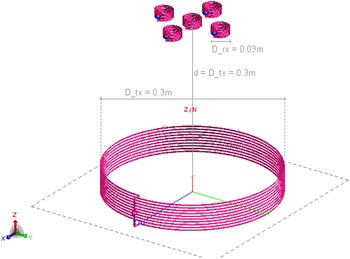
Accordingly, pursuing the deployment of RIC-WPT technology in multiple receiver applications with inevitable inter-coupling effects, it is necessary to revisit the current models of RIC-WPT systems from the SIMO perspective and to find new performance metrics and analytical procedures to optimize the behavior of such systems and design their parameters in turn predicting their interfering or relaying nature (see Fig. 1 for a representative deployment scenario, corresponding also to the numerical simulation setup used to characterize the system and validate the analysis).
Multi-node RIC-WPT system.

The paper henceforth proceeds in Section II by revisiting the design-oriented model relay effects in point-to-point RIC links, followed in Section III by a proposed analytical model to analyze and predict the behavior of relaying effects in multi-node RIC systems via a circuit-based matrix multidimensional model.
This multimdimensional model is finally considered in Section IV to perform a design-space exploration of the effects of internal loss-inducing resistances (corresponding to transmitter, interfering and load elements) in the frequency-dependent system efficiency, in pursuit of providing design guidelines for the relaying capabilities of the nodes.
II. REVISITING RELAY EFFECTS IN RIC-WPT
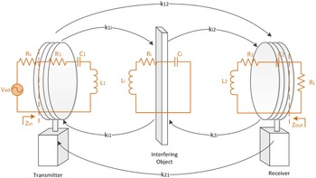
When a conductive element is in the vicinity of an RIC link, both the transmitter and the receiver can experience a change in their resonant frequencies as well as their impedances, which can greatly affect the efficiency of the WPT link [Reference Bou-Balust, Sedwick, Fisher and Alarcon20, Reference Bou-Balust, Alarcon, Vidal and Sedwick23]. However, depending on the impedance of the interfering object as well as its resonant frequency and coupling to transmitter and receiver, it can act as a relay thereby increasing the power transferred to the receiver load (P L ) and the efficiency (η = P L /P in ). To analyze this effect, an analytical model of the interfering object and its relationship with the RIC point-to-point link is given in this section (Fig. 2) based on the circuit theory. The interfering object is approximated by an RLC circuit that models the frequency response of its impedance (which depends on the object geometry, size, and material) and the coupling coefficients (k 1i , k i1, k i2, k 2i ), which model the magnetic behavior of the interference, this is, the amount of magnetic field that is effectively transferred between the interfering object and the transmitter/receiver coils.
Point-to-point RIC-WPT link with interfering object.

The gain functions of transmitter, receiver and interfering object can be derived from the circuit model of a point-to-point link [Reference Kiani and Ghovanloo6] and defined as:
 $$\matrix{ {{Y_1} = \displaystyle{{{I_1}} \over {{V_1}}} = \displaystyle{1 \over {{Z_1}}};} \hfill & {{Y_2} = \displaystyle{{{I_2}} \over {{V_2}}} = \displaystyle{1 \over {{Z_2}}};} \hfill & {{Y_i} = \displaystyle{{{I_i}} \over {{V_i}}} = \displaystyle{1 \over {{Z_i}}}} \hfill \cr} ;$$
where ω is the frequency at which the system operates. ω 1, ω 2, and ω i will then be the resonant frequencies of transmitter, receiver and interfering object respectively, defined as the frequencies at which the impedance is real. Z 1i , Z i1, Z 2i , Z i2 are defined as the trans-impedances, which describe the transfer functions from the transmitter/receiver to interfering object, and from the interfering object to transmitter/receiver, governing the distribution of power that arrives to the transmitter and receiver from the interfering object and vice versa. Finally, Z 12 and Z 21 represent the power coupled directly from transmitter to receiver and from receiver to transmitter, respectively.
 $$\eqalign{{Z_{1i}} = & \displaystyle{{{V_{i1}}} \over {{I_1}}} = j\omega {k_{1i}}\sqrt {{L_1}{L_i}} ;\quad {Z_{2i}} = \displaystyle{{{V_{i2}}} \over {{I_2}}} = j\omega {k_{2i}}\sqrt {{L_2}{L_i}} ; \cr {Z_{12}} = & \displaystyle{{{V_{21}}} \over {{I_1}}} = j\omega {k_{12}}\sqrt {{L_1}{L_2}}.} $$
Once the gain functions are known, the currents at transmitter (I 1), receiver (I 2), and interfering object (I i ) can be found to be:
 $${I_1} = {V_{ad}}\displaystyle{{{Y_1}} \over {1 + A + B}},$$
 $$A = {Y_1}{Z_{i1}}\displaystyle{{({Y_i}{Z_{1i}} + {Y_i}{Y_2}{Z_{12}}{Z_{2i}})} \over {1 + {Y_i}{Y_2}{Z_{2i}}{Z_{i2}}}},$$
 $$B = {Y_1}{Z_{21}}\displaystyle{{({Y_2}{Z_{12}} + {Y_i}{Y_2}{Z_{1i}}{Z_{i2}})} \over {1 + {Y_i}{Y_2}{Z_{2i}}{Z_{i2}}}},$$
 $${I_2} = {I_1}\displaystyle{{{Y_2}{Z_{12}} + {Y_i}{Y_2}{Z_{1i}}{Z_{i2}}} \over {1 + {Y_i}{Y_2}{Z_{2i}}{Z_{i2}}}},$$
 $${I_i} = {I_1}\displaystyle{{{Y_i}{Z_{1i}} + {Y_i}{Y_2}{Z_{12}}{Z_{2i}}} \over {1 + {Y_i}{Y_2}{Z_{2i}}{Z_{i2}}}}.$$
The power dissipated in the first coil (transmitter), the power dissipated in the second coil (receiver), the power transferred to the load, and the power lost in the interfering object can be defined as:
 $$\matrix{ {{P_1} = \displaystyle{{ \vert {I_1}{ \vert ^2}} \over 2}{R_1};\quad {P_2} = \displaystyle{{ \vert {I_2}{ \vert ^2}} \over 2}{R_2};\quad {P_L} = \displaystyle{{I_2^2} \over 2}{R_L};\quad {P_i} = \displaystyle{{I_i^2} \over 2}{R_i}} \hfill \cr} ;$$
where R 1, R 2, R L , and R i are the real part of Z 1, Z 2, Z L , and Z i , respectively.
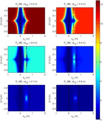
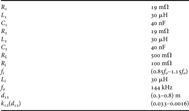
Figure 3 shows the power available at the load (P L ) for a set of different distances between transmitter and receiver when the impedance of the interfering object is small with respect to the load impedance (R i = 0.2R L ). The system of Fig. 3 consists of a transmitter and a receiver separated at a variable distance (d 12) between 0.3 and 0.8 m (λ/151 and λ/56), corresponding to the six subplots of the figure (straight and dotted black lines showcase the position of the transmitter and receiver, respectively). The system parameters for this analysis are provided in Table 1. An interfering object is then added to the system with a variable resonant frequency (f i , y-axis) and at a variable position from the transmitter (x i1, x-axis). The power obtained from the receiver load is displayed for each configuration of distance between transmitter and receiver (d 12, expressed in absolute distance [m]) and for every interfering object position. The results are summarized below:
-
• When the distance between transmitter and receiver (d 12) is smaller in more than a decade and an interfering object is placed between both, the system experiences an overcoupling and impedance mismatch in both source and load, thereby acting as an interference.
-
• When the distance between transmitter and receiver is such that the presence of the interfering object between both does not overcouple the system, the interference acts as a relay, this is, the presence of the interfering object increases the power available at the load (or could otherwise extend the range). This effect can be easily seen for distances larger than 0.5 m (d 12 > 0.5 m or d 12 > λ/91). Also, since the system experiments a frequency shift, the power is better transferred when the interfering object does not resonate at the same frequency than the receiver and transmitter. This is due to an overcoupling and impedance mismatch caused by the interfering load itself.
-
• For large distances between transmitter and receiver (d 12 > 0.6 m or d 12 > λ/75), it can be seen that the power is only effectively transferred to the load when the interfering object is between the transmitter and the receiver, demonstrating the relay effect of such system.
-
• For very large distances, when the system is not overcoupled, the interfering object acts as a better relay when the resonant frequency of the interfering object (f i ) is equal to the resonant frequency of transmitter (f o1) and to the resonant frequency of the receiver (f o2): f i = f o1 = f o2.
Load power exploration. Low impedance interfering object (R i = 0.2R L ).

System parameters for load power exploration – low impedance interfering object.

III. EXTENDING RELAY EFFECTS IN MULTIPLE-NODE RIC-WPT SYSTEMS
Once the relaying effects of an interfering object in a RIC-WPT link are known, it is possible to extend this analysis to a multi-node RIC WPT scenario, in which a SIMO system can have several nodes acting as relays that enhance the behavior of the system through a multi-path relaying effect. SIMO, which generally stands for SIMO systems are used in this context as a denomination of a RIC-WPT with single transmitter or input power port and multiple receiver or output power ports, not to be confused with the stablished use of SIMO/multiple-input–multiple-output (MIMO) in the communications discipline to connote methods for multiplying the capacity of a radio link [Reference Almers33].
To analyze this behavior, an analytical model of a MIMO system can be used [Reference Bou-Balust, Sedwick, Hu and Alarcon5], in which the behavior of the system is defined by the equations:
 $$\left( {\matrix{ {{I_1}} \cr {{I_2}} \cr {..} \cr {{I_n}} \cr}} \right) = \left( {\matrix{ 0 & {{Z_{21}}{Y_1}} & {..} & {{Z_{n1}}{Y_1}} \cr {{Z_{12}}{Y_2}} & 0 & {..} & {{Z_{n2}}{Y_2}} \cr {..} & {..} & {..} & {..} \cr {{Z_{1n}}{Y_n}} & {{Z_{2n}}{Y_n}} & {..} & 0 \cr}} \right)\left( {\matrix{ {{I_1}} \cr {{I_2}} \cr {..} \cr {{I_n}} \cr}} \right) + \left( {\matrix{ {{V_1}{Y_1}} \cr {{V_2}{Y_2}} \cr {..} \cr {{V_n}{Y_n}} \cr}} \right).$$
To analyze the relaying effect, only three different types of nodes are considered: a transmitter node G t , a receiver node G r and the interfering/relaying nodes G i . Under this assumption, the system of equations is particularized to:
 $$\left( {\matrix{ {{I_t}} \cr {{I_i}} \cr {{I_i}} \cr {{I_r}} \cr}} \right) = \left( {\matrix{ 0 & {{Z_{ti}}{Y_t}} & {{Z_{ti}}{Y_t}} & {{Z_{tr}}{Y_t}} \cr {{Z_{ti}}{Y_i}} & 0 & {{Z_{ii}}{Y_i}} & {{Z_{ir}}{Y_i}} \cr {{Z_{ti}}{Y_i}} & {{Z_{ii}}{Y_i}} & 0 & {{Z_{ir}}{Y_i}} \cr {{Z_{tr}}{Y_r}} & {{Z_{ir}}{Y_r}} & {{Z_{ir}}{Y_r}} & 0 \cr}} \right)\left( {\matrix{ {{I_t}} \cr {{I_i}} \cr {{I_i}} \cr {{I_r}} \cr}} \right) + \left( {\matrix{ {V{Y_t}} \cr 0 \cr 0 \cr 0 \cr}} \right).$$
Solving this system of equations for N nodes and considering that (1) the coupling between the transmitter and all the interfering objects is the same; (2) the coupling between all the interfering objects and the receiver is the same; and (3) the interfering objects are only coupled to the adjacent nodes; it is obtained:
 $$\matrix{ {{I_t} = \displaystyle{{V{Y_t}[(N - 2){Y_i}{Y_r}Z_{ri}^2 + 2{Y_i}{Z_{ii}} - 1]} \over A},} \cr {{I_i} = \displaystyle{{V{Y_i}{Y_t}[{Z_{ti}} + {Y_r}{Z_{ri}}{Z_{tr}}]} \over A},} \cr {{I_r} = \displaystyle{{V{Y_r}{Y_t}[{Z_{tr}}(1 - 2{Y_i}{Z_{ii}}) + (N - 2){Y_i}{Z_{ri}}{Z_{ti}}]} \over A},} \cr } $$
where
 $$\eqalign{A = & \,(N - 2){Y_i}[{Y_r}{Z_{ri}}(2{Y_t}{Z_{ti}}{Z_{tr}} + {Z_{ri}}) + {Y_t}Z_{ti}^2 ] \cr & + 2{Y_i}{Z_{ii}}(1 - {Y_r}{Y_t}Z_{tr}^2 ) + {Y_r}{Y_t}Z_{tr}^2 - 1,} $$
and the current is the same in any of the interfering nodes. Once the currents are known, the power at the transmitter P t , the power at each interfering/relaying node P i , the power at the receiver P r and the power transferred to the load P rl are:
 $$\matrix{ {{P_t} = \left\vert{I_t}\right\vert^2\ {\rm \opf R}\displaystyle{1 \over {2{Y_t}}}; \hfill {P_i} = \left\vert{I_i}\right\vert^2\ {\rm \opf R}\displaystyle{1 \over {2{Y_i}}},} \cr {{P_r} = \left\vert{I_r}\right\vert^2\ {\rm \opf R}\displaystyle{1 \over {2{Y_r}}}; \hfill {P_{rl}} = \displaystyle{{\left\vert{I_r}\right\vert{^2}} \over 2}{R_L}.} \cr } $$
The total input power of the system can be found equal to the sum of the powers as:
 $$\eqalign{{P_{in}} =\; & {P_t} + \sum\limits_{N - 2} {P_{i,N}} + {P_r} = {P_t} + (N - 2){P_i} + {P_r} \cr =\, & {V^2}\displaystyle{{Y_t^2 {{(({N_2}){Y_i}{Y_r}Z_{ri}^2 + 2{Y_i}{Z_{ii}} - 1)}^2}} \over {{A^2}}}{\rm \opf R}{Z_t} \cr & + (N - 2){V^2}\displaystyle{{{{({Y_i}{Y_t}[{Z_{ti}} + {Y_r}{Z_{ri}}{Z_{tr}}])}^2}} \over {{A^2}}}{\rm \opf R}{Z_i} \cr & + {V^2}\displaystyle{{{{({Y_r}{Y_t}[{Z_{tr}}(1 - 2{Y_i}{Z_{ii}}) + (N - 2){Y_i}{Z_{ri}}{Z_{ti}}])}^2}} \over {{A^2}}}{\rm \opf R}{Z_r}.} $$
And the output power of the system is equivalent to the power transferred to the load:
 $${P_{out}} = {V^2}\displaystyle{{{{({Y_r}{Y_t}[{Z_{tr}}(1 - 2{Y_i}{Z_{ii}}) + (N - 2){Y_i}{Z_{ri}}{Z_{ti}}])}^2}} \over {{A^2}}}{R_L}.$$
Finally, the efficiency of the system is defined as:
 $$\eqalign{ \eta = & \displaystyle{{{P_{out}}} \over {{P_{in}}}} = \displaystyle{{{{({Y_r}{Y_t}[{Z_{tr}}(1 - 2{Y_i}{Z_{ii}}) + (N - 2){Y_i}{Z_{ri}}{Z_{ti}}])}^2}{R_L}} \over {D + E + F}}, \cr & D = Y_t^2 {(({N_2}){Y_i}{Y_r}Z_{ri}^2 + 2{Y_i}{Z_{ii}} - 1)^2}\ {\rm \opf R}({Z_t}), \cr & E = (N - 2){({Y_i}{Y_t}[{Z_{ti}} + {Y_r}{Z_{ri}}{Z_{tr}}])^2}\ {\rm \opf R}({Z_i}), \cr & F = {({Y_r}{Y_t}[{Z_{tr}}(1 - 2{Y_i}{Z_{ii}}) + (N - 2){Y_i}{Z_{ri}}{Z_{ti}}])^2}\ {\rm \opf R}({Z_r}).} $$
IV. CHARACTERIZING THE EFFECT OF RESISTANCE IN RELAY EFFECTS
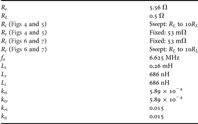
From the analytical model described above, it can be seen that the behavior of the system strongly depends upon the impedances of the transmitter, receiver, and interfering nodes. In this section, the resonant frequency has been designed to be the same in each node to fulfill two objectives: first, the target application of a multi-path relaying scenario is a SIMO system with some nodes acting as receivers and others acting as interfering/relaying nodes, which requires that all the nodes operate at the same frequency (in order to resonate when acting as receivers). Second, to maximize the relaying effect of the interfering object, the magnetic field transferred to it should be maximized. In such scenario, the resistive load of the interfering object (ohmic and radiative losses) relative to the transmitter and receiver resistances and the receiver load have a strong effect upon the behavior of the system. The effect of the node resistance on the relaying capabilities of the interfering nodes is analyzed in this section and illustrated with regards to the efficiency of the system. The system parameters for the results shown in this section are provided in Table 2. For this purpose a ten-node (one transmitter, one receiver, and eight interfering nodes) RIC-WPT system with the geometrical distribution displayed in Fig. 1 is studied, and chosen for its relevance within the application and because it is representative of the multi-node system behavior [Reference Bou-Balust, Hu and Alarcon34]. In this system, the coupling between transmitter and interfering nodes (k ti ), the coupling between receiver and interfering nodes (k ri ), and the coupling between adjacent interfering nodes (k ii ) have been considered equal (and obtained through the finite-element field solver FEKO). This section presents the effect of the transmitter, receiver and interfering node impedances upon the power transfer efficiency, calculated as the quotient between the power transferred to the system P in and the power obtained by the receiver P out through direct transmission (P in , out ) and through the interfering nodes (P j, out ; j = 1, …, 8).
System design variables.

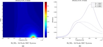
Figure 4 shows the power transfer efficiency (in percentage, normalized to 1) of the system for different values of interfering object resistance normalized to the load of the system. Figure 4(a) showcases the behavior of the system and Fig. 4(b) displays the frequency response for different values of R i for illustration purposes. In this figure, several behaviors can be observed:
-
• There is a positive multi-node relaying effect that increases the power transfer efficiency of the system when the losses of the interfering nodes are small compared with the load of the system (R i /R L < 3).
-
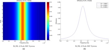
• When the interfering object resistance is high compared with the load resistance, the interfering objects have no effect upon the power transfer efficiency. Looking at Fig. 5 it is possible to observe that the system with eight interfering nodes has the same power transfer efficiency as a system without any interfering nodes, provided that their resistance is high compared with the load of the system R i > 9R L .
-
• The relaying effect also causes a change of the frequency at which maximum power transfer efficiency is obtained, which causes a frequency deviation from the resonant frequency of the system.
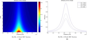
Analogous results are shown in Fig. 5 for a system with no interfering object (2 nodes: transmitter and receiver). It can be seen that the system response to a change on the interfering object resistance is null, which is consistent with having no interfering nodes. However, this figure is shown here to provide a fair comparison of the system behavior with and without interfering objects.
Interfering resistance – RIC-WPT system with eight Relaying nodes. (a) R i /R L . Ten-node RIC system. (b) R i /R L . Ten-node RIC system.

Interfering resistance – RIC-WPT system without Relaying nodes. (a) R i /R L . Two-node RIC system. (b) R i /R L . Two-node RIC system.

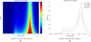
It is of interest to characterize not only the effect of the interfering resistance, but also the effect of transmitter resistance upon single-node and multi-node RIC-WPT systems. Figures 6 and 7 showcase this effect for multi-node and single-node scenarios, respectively.
Transmitter Resistance – RIC-WPT system with eight Relaying nodes. (a) R i /R L . Ten-node RIC system. (b) R i /R L . Ten-node RIC system.

Transmitter resistance – RIC-WPT system without Relaying nodes. (a) R i /R L . Two-node RIC system. (b) R i /R L . Two-node RIC system.

Comparing the two figures, it is possible to observe that an increase in the transmitter losses has a detrimental effect in both cases. However, due to the presence of the relaying nodes, higher power transfer efficiency can be obtained even with a high transmitter resistance compared with the receiver load. Finally, it is possible to calculate the maximum efficiency in both scenarios (with and without relaying nodes).
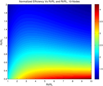
Figure 8 shows the normalized efficiency η multi−node /η pp for different interfering object resistance and transmitter resistance values (normalized to the load resistance of the system) where it can be observed that: (1) when the interfering object resistance is small, the power transfer efficiency is greatly increased with respect to the efficiency without any relaying nodes; (2) when the interfering object resistance is close to the load resistance, the increase in efficiency is still significant (around twice the efficiency without relaying nodes); and (3) the relaying effect starts to be negligible when the resistance of the relaying nodes is higher than the load resistance. Finally, it is important to note that for a given R i there is an optimal R t that maximizes the efficiency. In point-to-point systems, the output resistance of the system is optimal in terms of efficiency for a given R L , RT [Reference Bou-Balust, Sedwick and Alarcon8, Reference Chabalko, Alarcon, Bou-Balust and Ricketts9]. Translating this to a multi-node scenario means that there is a combination of R L and reflected impedances of the interfering nodes R i that optimize the same output resistance. It is possible to observe that when the resistance of the transmitter is low, the system acts in the overcoupled regime, thereby requiring higher interfering node impedances to counteract this effect. On the other hand, if a higher transmitter resistance is considered, the required interfering node impedance to operate in maximum efficiency conditions is lowered. The main purpose of Fig. 8 is to provide system design guidelines and in turn a method to realize the best efficiency when considering as open design variables the coil parasitic resistances for the multi-receiver scenario characterized in this work.
Efficiency normalized to efficiency without interfering nodes.

V. CONCLUSION
In this work, the relaying effects in point-to-point resonant inductive coupling WPT link have been revisited and extended to the scenario of multiple-node systems potentially acting as relays showing interdependence. This extended study has been carried out by means of an analytical circuit-based multidimensional model. Beyond such formal extension and its corresponding matrix description, the paper uses the model and provides its benchmark validation with electromagnetic numerical simulations to characterize multi-coil relaying effects. The study considers representative implementation, design, and application variables such as resistances of the transmitter, receiver and interfering nodes in the SIMO WPT system, thereby providing a design-oriented exploration of relay effects in multiple receiving coil systems both unveiling fundamental limits and practical interest in WPT system deployments. This work demonstrates a multi-node RIC-WPT scenario which could potentially benefit a lot of applications such as wireless sensor networks and IoT. Future work should address the compliance of human safety regulations in these scenarios.
ACKNOWLEDGEMENTS
Partial funding by Thales Alenia Space Spain and partial funding by projects TEC2010-15765 and RUE CSD2009-00046 (Consolider-Ingenio 2010), from the Spanish Ministry of Science and Innovation is acknowledged.
 E. Bou-Balust received the M.Sc. degree in Telecommunications Engineering from Technical University of Catalonia (UPC) in 2011 and the M.Sc. in Electronic Engineering from the University of Las Palmas de Gran Canaria (ULPGC) in 2011. Since 2012 she has been a Ph.D. candidate at Technical University of Catalonia on Resonant Inductive Coupling Wireless Power Transfer Systems. Bou was a recipient of two Vodafone Scholarships (2008 and 2009), a research grant issued by Thales Alenia Space Spain (2012–2016) on Wireless Energy Transfer for satellite constellations and a Google Faculty Research Award (2013) on Android Phone-Based Nano-Satellites. Bou collaborates with the UMD Aerospace Engineering Department and the MIT Aeronautics and Astronautics Department on Space Applications of Resonant Inductive Coupling WPT. She serves as a reviewer for the IEEE IAS, IEEE MWSCAS, IEEE IMS, and IEEE BIOCAS amongst others and co-organized special sessions related to wireless energy transfer at IEEE ISCAS (2013, 2014) and PIERS (2013, 2014).
 Raymond J. Sedwick is an Associate Professor of Aerospace Engineering and Director of the Space Power and Propulsion Laboratory at the University of Maryland where he has been since Fall of 2007. He is also recognized as a Keystone Professor within the A. James Clark School of Engineering and is the Director of the Aerospace Engineering Honors Program. Dr. Sedwick's current research includes orbital debris remediation, RF plasma generation for space propulsion, plasma-assisted combustion and catalyzed decomposition, ion plume material impact damage, and novel fusion confinement for space and terrestrial power applications. His research interests include a variety of in-space power generation and propulsion technologies, with particular interest in nuclear systems and the applications of plasmas. Dr. Sedwick was the inaugural recipient of the Bepi Colombo Prize, as well as the recipient of an NSF CAREER award on the development of compact helicon sources. He is an Associate Fellow of the AIAA, an Associate Editor of the AIAA Journal of Spacecraft and Rockets, and serves on the AIAA Nuclear and Future Flight Technical Committee. Dr. Sedwick received a BS in Aerospace Engineering from Penn State University in 1992, and an M.S. and Ph.D. from the MIT Department of Aeronautics and Astronautics in 1994 and 1997.
 P. H. Fisher is a Professor in the Physics Department and currently serves as department head at the Massachusetts Institute of Technology. He carries out research in particle physics in the areas of dark matter detection and the development of new kinds of particle detectors. He also has an interest in compact energy supplies and wireless energy transmission. Professor Fisher received a B.S. Engineering Physics from Berkeley in 1983 and a Ph.D. in Nuclear Physics from Caltech in 1988.
 E. Alarcon received the M. Sc. (National award) and Ph.D. degrees (honors) in Electrical Engineering from the Technical University of Catalunya (UPC BarcelonaTech), Spain, in 1995 and 2000, respectively. Since 1995 he has been with the Department of Electronic Engineering at UPC, where he became Associate Professor in 2000. From August 2003 to January 2004, July–August 2006 and July–August 2010 he was a Visiting Professor at the CoPEC center, University of Colorado at Boulder, USA, and during January–June 2011 he was Visiting Professor at the School of ICT/Integrated Devices and Circuits, Royal Institute of Technology (KTH), Stockholm, Sweden. He has co-authored more than 250 scientific publications, four books, four book chapters and four patents, and has been involved in different National, European and US (DARPA, NSF) R&D projects within his research interests including the areas of on-chip energy management circuits, energy harvesting, wireless energy transfer, and nanotechnology-enabled wireless communications. He is the PI of the Guardian Angels EU FET flagship project at UPC and through N3CAT center he is part of the graphene flagship. He has given 25 invited or plenary lectures and tutorials in Europe, America and Asia, was appointed by the IEEE CAS society as distinguished lecturer for 2009–2010 and lectures yearly MEAD courses at EPFL. He has participated in Evaluation Boards for research proposals both in Europe (Chist-ERA, Belgium, Ireland, Italy) America (Canada) and Asia (Korea). He is elected member of the IEEE CAS Board of Governors (2010–2013) and member of the IEEE CAS long-term strategy committee.