1. Introduction
As science and technology developed, robots and their improvement have been needed to be increased in various fields. Mobile robots have been successfully employed in different areas, such as medical, planetary exploration, agricultural machinery, and object moving [Reference Hu, Su, Fu, Karimi, Ferrigno, De Momi and Knoll1–Reference Dönmez and Kocamaz4]. So far, many control methods have been used for mobile robots, and for choosing one of them, systems’ linearity and nonlinearity, the design purpose, environment conditions, and the issue’s constraints should be considered [Reference Lee and Kim5]. The proportional – integral – derivative (PID) controller’s simple structure is superior to other linear controller types. In order to increase the performance accuracy of this controller, Elsisi et al. have presented a method based on modified neural networks to extract the optimal gains of this controller, which performed better than the conventional way for robotic manipulators [Reference Elsisi, Mahmoud, Lehtonen and Darwish6]. However, controllers with more optimal capabilities have been studied and employed as control methods develop and the more profound need for more accuracy, speed, and flexibility. The linear quadratic regulator (LQR) is another type of linear controller known as a common and widely used type due to its optimal solution. Xin et al. have implemented the system’s controller with reverse dynamic control to track the path of a four-legged mobile robot reliably; in this way, the current status of the robot is rapidly updated, and the desired values have been sent to the actuators by minimizing the cost function of LQR controller [Reference Xin, Xin, Cebe, Pollayil, Angelini, Garabini, Vijayakumar and Mistry7]. In another study, they have used the LQR controller with the Extended Kalman Filter Estimator method for underwater mobile robot positioning problems and proposed a method to determine it accurately [Reference Alalwan, Mohamed, Chakir and Laleg8]. Trimp et al. have suggested a method for extracting better coefficient from the LQR controller’s cost function to reduce inverted pendulum vibrations. This method’s problem is its dependence on SPSA optimization parameters, and its optimization is limited to the last step data [Reference Trimpe, Millane, Doessegger and D’Andrea9]. Big bang-big crunch (BB-BC) optimization algorithm has been used for a pendulum on a cart to find the cost function’s weighting matrices [Reference Almobaied, Eksin and Guzelkaya10]. Kayacan and Chowdhary have proposed the Tracking-Error Learning Control algorithm to improve off-road mobile robots’ tracking. In this algorithm, the feedforward control actions are updated using tracking error dynamics, and the problem of the model is eliminated. The results showed improved performance in the control system [Reference Kayacan and Chowdhary11]. Dönmez et al. have proposed a method called Bi-RRT based on vision for path planning a wheeled mobile robot (WMR) and obstacle avoidance [Reference Dönmez, Kocamaz and Dirik12].
Since most systems are generally nonlinear, there is a considerable difference between the actual and the modeled system when the system is linearized, which reduces the accuracy of the controller’s performance in practical applications. In this regard, using a nonlinear model that needs a nonlinear controller to solve makes a better outlook of the system’s actual behavior. State-Dependent Riccati Equation, which was studied for the first time in robotics by Innocenti et al., can be described as one of the useful and optimal nonlinear controllers [Reference Innocenti, Baralli, Salotti and Caiti13]. Korayem et al. have employed this controller to determine the maximum load of mechanical manipulators with flexible joints. R and Q matrices’ effects on the path have been considered, and the results compared with the LQR controller [Reference Korayem, Irani and Nekoo14]. A finite-time feedback linearization controller has been implemented on the manipulators of a mobile robot. The optimal gain is obtained by solving the state-dependent differential Riccati equation in a time-varying dynamic system to achieve a finite time constraint [Reference Korayem, Nekoo and Kazemi15]. Hun Lee et al. have suggested a method for generating and regulating joint torque at each time step in legged robots. In this way, actual torque or force has been directly used in control loops instead of feedforward force, which results in better performance [Reference Lee, Lee, Lee, Kang, Lee, Park, Kim, Moon, Koo and Choi16].
Korayem et al. have introduced an approach to improve the sliding mode control (SMC) in the robotic manipulators called nonsingular terminal SMC, simulated and implemented for the Scout mobile robot manipulators. The results indicate that this method’s performance error was less than the conventional method [Reference Korayem, Shiri, Nekoo and Fazilati17].
The model predictive control (MPC) is a perfect controller for mobile robots in different environments. This controller predicts some of the future steps to make better decisions, especially in unknown environments, so its performance is desirable and reliable. This controller’s accuracy and solution speed for a differential mobile robot has been studied and compared in the nonlinear and stable mode [Reference Adriani, Lademakhi and Korayem18]. In another study, the problem of path tracking control has been solved by combining MPC for the kinematic part and adaptive control for the dynamic part [Reference Chen, Li, Kong and Ke19]. A Hierarchical Decomposed-Objective based on Model Predictive Control (HiDO-MPC) has been proposed to improve the performance of this controller used in rescue robots to approach the casualty, which has demonstrated results in enhancing accuracy and speed [Reference Saputra, Rakicevic, Chappell, Wang and Kormushev20].
Extracting a model close to the existing system is necessary for good control performance. Fierro and Lewis have provided the kinematic and dynamic model of WMRs with n-dimensional configuration space S. Also, a robust-adaptive controller based on neural networks for trajectory tracking has been proposed [Reference Fierro and Lewis21]. Another dynamic model of a WMR with manipulators has been extracted and presented by recursive Gibbs–Appell formulation. This method’s benefit is omitting computing the Lagrange multipliers associated with the nonholonomic system constraints [Reference Korayem and Shafei22]. Dönmez et al. have presented a visual-based technique to increase the accuracy of WMRs’ controller act. The kinematic model has been extracted using the general Gaussian function, and the system control works in real-time. In this method, they need to calculate just one function to adjust system velocity parameters, which is a faster method for real time [Reference Dönmez, Kocamaz and Dirik23].
The development of machine learning has solved the absence of an exact mathematical system model and causes no more trial and error to achieve the controlling desire. It is reasonable to say that combining classic and modern controllers with machine learning methods can be helpful and achieve excellent accuracy. Chen et al. have presented an adaptive neural networks control scheme for a WMR to compensate system’s uncertainties by approximating its uncertain parameters, which improved system robustness [Reference Chen, Liu, He, Qiao and Ji24]. Recently, Peng et al. have developed neural networks based on adaptive control for optimal path tracking when environmental information is unavailable [Reference Peng, Chen and Yang25]. A computational method called QRnet based on machine learning has been proposed to design optimal gains for high-dimensional nonlinear systems using an LQR controller. However, this method has been limited to the “is it possible to approximate the original problem to a linear-quadratic system” question [Reference Nakamura-Zimmerer, Gong and Kang26]. Yan et al. have presented an approach based on robust MPC influenced by finite uncertainties for discrete-time nonlinear systems. At first, the system has been linearized, and then the MPC signal has been optimized with a recursive neural network [Reference Yan, Le and Wang27]. Also, an nonlinear model predictive control (NMPC) technique based on Gaussian Particle Swarm Optimization has been employed, that a linear equivalent is extracted and solved for the system in each solution’s step; however, it causes a reduction in the method solution’s speed [Reference Fan and Han28]. Linearizing the model in the two last methods increases practical errors.
There are some gains in each controller, which must be optimally extracted and regulated for better performance. In controllers with cost function, there are two weighting matrices, Q and R, to optimize and obtain control output state and system input variables, which changing them affects the tracking of the path significantly. Therefore, it is necessary to extract these gains for each situation by trial and error method to improve the controller performance, and it requires a lot of time and energy. This paper proposes an intelligent controller based on neural networks, with the following four innovations: 1. Extracting the cost function’s weighting matrices for every path without wasting operator time and effort. 2. Improving the controller’s accuracy by intelligently selecting the gains separately in each solution step. 3. Presenting a predictive training method based on MLP-NN to extract gains with an outlook on future steps. 4. Better accommodating the networks with new paths by training them based on system state variables. The structure of the paper is illustrated as follows. Part II will discuss the MLP-NN structure and the suggested method for network training to extract control gains. There is a review of two controllers with the cost functions, LQR and NMPC, in Section III. Section IV deals with the kinematic modeling of a wheeled mobile robot (WMR) in both linear and nonlinear formulations and introduces the experimental robot. Then, in Section V, in addition to simulation results and their comparison, actual test results for the four-WMR are presented and reviewed. Discussing the results is followed in Section VI, and finally, the conclusions are provided in Section VII.
2. Controller’s weighting matrices regulation
2.1. Neural network training method considering the future steps
The method starts with data collecting and network training. The most critical question is: what inputs are suitable for training the network? In this case, the first method for tracking by a mobile robot seems to be putting the path type as the network’s input and the best Q and R for each of them as the network’s output. There are some problems with this assumption; first, the amount of data is limited by path type, and a meager amount of data is extracted; so the network has a low accuracy for new paths. Second, the network is not trained in the actual control concept (the system’s state variables) and causes little efficiency in new situations. Therefore, the best solution is to collect and use data based on the system’s state variables at each time step; In this way, the differences between the variables of the current and the reference states are given to the neural network at every time step, and its weighting matrices are extracted and used. So, not only can much more data be extracted to train the network, but also it will work much better for new paths since states’ errors are more adaptable than the path type.
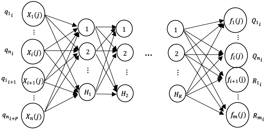
However, the best way to train has been discovered, but the network decisions are still limited to the current particular step. The proposed method can perform better along the path by entering the system’s future state variables in network decisions. In this case, the network trained with this method will extract control gains by looking at the future path changes. So, according to Fig. 1, the network’s input is extracted in the form of Eq. (1).
 \begin{equation} \psi(i)=\left[\!\begin{array}{ccc} q_{{1_{i}}}(k)\;\; & q_{{2_{i}}}(k) & \begin{array}{ccc} \;\;\ldots\;\; & q_{{n_{i}}}(k)\;\; & \begin{array}{ccc} q_{{1_{i}}}(k+1)\;\; & q_{{2_{i}}}(k+1) & \begin{array}{cc} \;\;\ldots\;\; & q_{{n_{i}}}(k+P) \end{array} \end{array} \end{array} \end{array} \right]^{T}\end{equation}
Where n is the number of state variables of the system,
 $q_{{1_{i}}}(k)$
is the difference between the first state variable and its reference state variable at the k moment,
 $q_{{n_{i}}}(k)$
is the difference between the n state variable and its reference at the exact moment,
 $q_{{1_{i}}}(k+1)$
is the difference between the first reference state at the k and k + 1 moments, and finally
 $q_{{n_{i}}}(k+P)$
is the difference between the n reference state at the k + P-1 and k + P moments. The data extraction has been done by Algorithm 1 to train the network.
Architecture of a neural network with k hidden layer(s).


3. Structure of controllers with cost function
In this paper, NMPC as a nonlinear controller and LQR as a linear controller have been used to validate the content. The primary reason for choosing them is that these two controllers have the cost function for optimization and require appropriate Q and R matrices. In addition, the NMPC is a perfect option for path tracking with a mobile robot since it can predict some of the future steps. The LQR controller has the flexibility to regulate better system inputs and inherent resistance to noise and disturbance.
3.1. LQR controller
Suppose the system equation in discrete linear form as Eq. (2) is extracted:
 \begin{align} x(k+1)&=A(k)x(k)+B(k)u(k)\nonumber \\[5pt]y(k)&=C(k)x(k)+D(k) \end{align}
The matrices A(k) and B(k) are the coefficients of the control state variables and the system inputs, respectively. Also, C(k) is defined as the state coefficient matrix in the system output equation, and external uncertainties and disturbances define D(k). The system’s cost function as Eq. (3) is minimized in this controller method:
 \begin{equation} J_{LQR}=\sum _{k=0}^{\infty }\left(X(k)^{T} Q X(k)+u(k)^{T} R u(k)\right) \end{equation}
Q and R values must be selected based on design requirements. After finding the coefficient matrix F(k), the system input is extracted as Eq. (4) by solving the controller at each step.
 \begin{equation} u(k)=-F(k)x(k) \end{equation}
3.2. NMPC
A discrete nonlinear system as (5) is assumed:
 \begin{align} x(k+1)&=f(x(k),u(k))\nonumber\\[5pt]y(k)&=h(x(k)) \end{align}
Which includes the constraints
 $u_{min}\leq u(k)\leq u_{max}$
and
 $y_{min}\leq y(k)\leq y_{max}$
.
 $x(k)\in R^{n}$
is the state variables vector and
 $u(k)\in R^{m}$
is the control input vector and also
 $y(k)\in R^{p}$
is the output vector. According to [Reference Meadows, Rawlings, Henson and Seborg29], the cost function of this controller has been extracted as Eq. (6):
 \begin{equation} J_{NMPC}=\varnothing (y(k+N|k))+\sum _{i=0}^{N-1}L(y(k+i|k),u(k+i|k),\Delta{u}(k+i|k)) \end{equation}
In this equation,
 $u(k+i|k)$
input and
 $u(k+i)$
are calculated from the available data at the k step, and also
 $y(k+N|k)$
output and
 $y(k+N)$
comes from the available data at the k step. C is the control horizon, N is the prediction horizon, and as Eqs. (7) and (8),
 $\varphi$
and L are two nonlinear functions that form the cost function.
 \begin{align} L&=(y(k+i|k)-y_{s}(k))^{T}Q(y(k+i|k)-y_{s}(k)) \nonumber\\[5pt] &\quad +(u(k+i|k)-u_{s}(k))^{T}R(u(k+i|k)-u_{s}(k))+\Delta{u^{T}}(k+i|k)S\Delta{u}(k+i|k)\end{align}
 \begin{equation} \varphi = (y(k+N|k)-y_{s}(k))^{T}Q(y(k+N|k)-y_{s}(k))\end{equation}
Where the targets of the steady states y and u are
 $y_{s}$
and
 $u_{s}$
.
Also, Q and R are, respectively, n × n and m × m, where n is the number of the system’s state variables and m is the number of control inputs. The difference between system inputs at the current step and the previous step is defined as
 $\Delta u(k+i|k)=u(k+i|k)-u(k+i-1|k)$
, and S has been used as the weighting matrix of the
 $\Delta u$
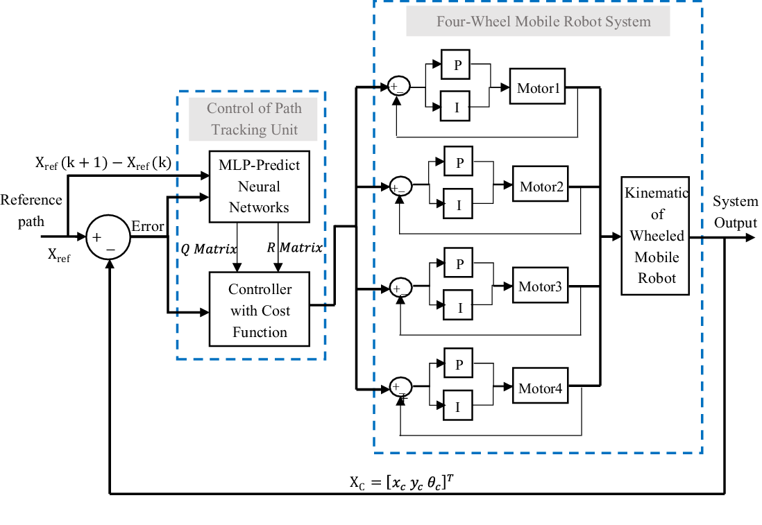
. Finally, the block diagram of the intelligent controller for tracking the path by the WMR is shown in Fig. 2. As can be seen, a PI controller is used to control the speed of the Dynamixel motors for their better performance, and the motors use this controller by default. Relative to the reference coordinates,
 $X_{c}(k)$
is the states value of the robot’s center of mass (COM) at the k step, and
 $X_{ref}(k)$
is the state value of reference at the same step.
Intelligent path tracking block diagram for WMRs with adjustment of the cost function.

4. WMR modeling and introduction
4.1. Kinematic of a WMR
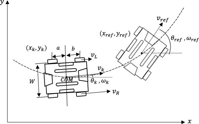
The schematic of the system, the mechanical motion structure, and the distribution of velocity vectors have been shown in Fig. 3, where the robot’s center of mass is marked with COM. As can be seen, the robot on the screen moves in the x and y directions and has a rotation angle θ. An ideal reference robot has been considered to follow the path and move according to the desired values, so the real robot must always follow it.
The schematic of the robotic motion structure and the distribution of velocity vectors.

The state variables of the system are assumed to be
 $q=\left[\begin{array}{ccc} x & y & \theta \end{array}\right]^{T}$
which are related to the general coordinates. It can be considered that there is no slip in the system, so the friction between the wheels and the floor has been neglected in this study. The linear velocity of each wheel is equal to the angular velocity of the wheel multiplied by its radius. Thus the kinematic of the WMR is extracted as Eq. (9) [Reference Wu, Xu and Wang30].
 \begin{equation}\left[\begin{array}{c} \dot{x}_{c}(t)\\ \dot{y}_{c}(t)\\ \dot{\theta }(t) \end{array}\right]=\left[\begin{array}{c@{\quad}c} cos\theta (t) & 0\\ sin\theta (t) & 0\\ 0 & 1 \end{array}\right]\left[\begin{array}{c} v_{COM}(t)\\ \omega _{COM}(t) \end{array}\right] \end{equation}
Where
 $v_{COM}(t)$
is the linear velocity of the robot’s COM in the direction of the longitudinal axis, and
 $\omega _{COM}(t)$
is the angular velocity of the robot’s COM around its vertical axis. Physically, two wheels on the same side of the robot must move at the same speed. In this case, the conversion matrix of the COM’s linear and angular velocities to the right and left velocities has been expressed as Eq. (10), that W is the width of the robot.
 \begin{equation}\left[\begin{array}{c} v_{COM}(t)\\ \omega _{COM}(t) \end{array}\right]=\left[\begin{array}{c@{\quad}c} \dfrac{1}{2} & \dfrac{1}{2}\\[12pt] \dfrac{1}{W} & -\dfrac{1}{W} \end{array}\right]\left[\begin{array}{c} v_{L}(t)\\ v_{R}(t) \end{array}\right] \end{equation}
The discretized kinematic model of the WMR corresponding to Fig. 3 has been extracted as Eq. (11).
 \begin{align} X(k+1)&=f(X(k),u(k))\nonumber \\[5pt]x(k+1)&=x(k)+(v(k)\,\textrm{cos} \theta(k))t_{s}\nonumber \\[5pt]y(k+1)&=y(k)+(v(k)\,\textrm{sin} \theta(k))t_{s}\nonumber \\[5pt]\theta(k+1)&=\theta(k)+\omega(k)t_{s} \end{align}
Where k is the current step and
 $t_{s}$
is sampling time. The system equations are linearized using the Taylor method’s linear controller in WMR. According to Ref. [Reference Sharma, Dušek and Honc31], the system’s discrete equations can be extracted as Eq. (12), and the matrices A(k) and B(k) can be seen as Eqs. (13) and (14), respectively:
 \begin{align} \tilde{q}(k+1) =A(k)\tilde{q}(K)+B(K)\tilde{u}(k) \end{align}
 \begin{align} A(k) =\left[\begin{array}{c@{\quad}c@{\quad}c} 1 & 0 & -v(k)\,sin\theta_{r}(k)\,t_{s}\\[5pt] 0 & 1 & v_{r}(k)\,cos\theta_{r}(k)\,t_{s}\\[5pt] 0 & 0 & 1 \end{array}\right] \end{align}
 \begin{align} B(k) =\left[\begin{array}{c@{\quad}c} cos\theta_{r}(k)\,t_{s} & 0\\[5pt] sin\theta_{r}(k)\,t_{s} & 0 \\[5pt] 0 & t_{s} \end{array}\right] \end{align}
4.2. Experimental setup of the robot
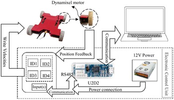
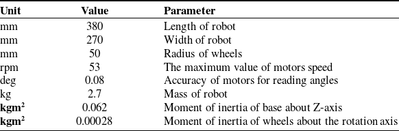
A four-WMR has been used to validate the results, shown in Fig. 4. The motors of this robot are Dynamixel type and XM540-W150-r model, which can be networked with each other, and various information such as position, speed, motor load, and input voltage can be extracted while receiving commands from the central controller. The robot’s main body is made of aluminum, which all motors, the network of motors, wires, and connections are placed on it. Finally, they are covered with a plexiglass surface, and A 12(V) - 30(A) power supply is used for the motors. The dimensional and mass charcteristics of the robot are shown in Table I.
Schematic of the experimental setup to track the path of a four-WMR.

The dimensional and mass characteristics of the robot.

To get feedback from the rotation angle of the robot body, the output of the motors’ encoders, or in other words, the amount of the wheels’ rotation, have been used; Thus, the rotation ratio of the right and left wheels determines the value of the angle.
For example, when the wheels’ rotation on both sides is equal, the body’s rotation value is zero, and when the rotations of the two sides are opposite, the robot rotates around itself, and the angle value is determined depending on the different rotation between two sides at each step time. Then, according to the distance between the robot’s COM and the wheels, the x and y positions of the robot are calculated, and the system state variables’ errors continue the loop.
Also, for better expression, the schematic of the experimental setup has been presented in Fig. 4. A U2D2 interface in the electrical box takes commands from the relevant software and sends them to the motors’ board via the RS485 protocol; also, the power supply is connected to the motors’ board. Finally, motors send requested information as feedback to the software, and the loop is completed.
5. Simulation and experimental tests
5.1. Network training to track the path
The number of future steps entered in computation has been considered as P = 29 for the WMR path tracking with n = 3 state variables, x, y, and θ; So there is 90 datum in each data set as the network input. The number of output data in each data set is 5, which includes three matrix elements of
 $Q_{i}=diag[{Q_{1}}_{i}\;\;\; {Q_{2}}_{i}\;\;\; {Q_{3}}_{i}]$
and two matrix elements of
 $R_{i}=diag[{R_{1}}_{i}\;\;\; {R_{2}}_{i}]$
. Therefore, with this operation, the output vector which is the best weighting matrices of the specific state, has consisted, and network training of MLP has been performed by the input and output vectors. At this step, the number of network layers and the number of nodes of each hidden layer are required. In this regard, the best numbers of the final network have been selected by testing different numbers and their performance results. The experiment test by the 4-WMR has been shown in Fig. 5.
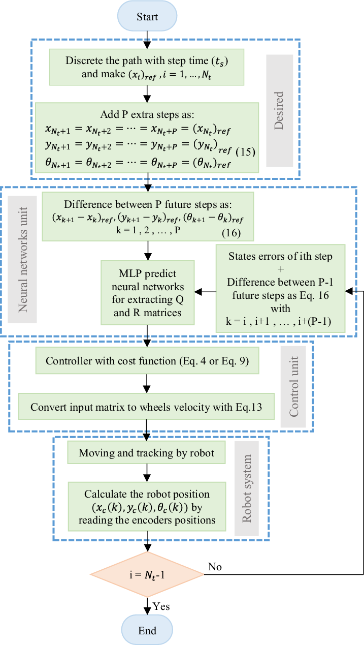
Executive flowchart of intelligent control to track the path by a WMR.

5.2. NN-LQR controller
At first, training data were collected for network learning, and 16,000 data sets were extracted by solving several different paths. According to Fig. 1, the best number of layers has been chosen after consecutive training as K = 4, and the number of hidden layers nodes as
 $H_{1}=H_{2}=H_{3}=H_{4}=5$
. This network has been trained in MATLAB software, and its function has been extracted; the least-squares error for this network training was
 $0.38\times 10^{-5}$
. An algorithm is needed to find the minimum function to implement this network with the MLP method.
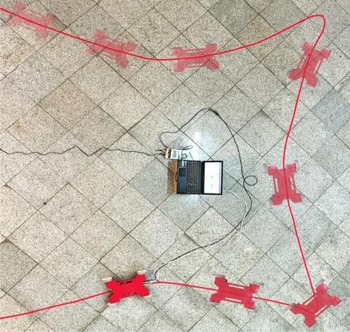
In this paper, the Levenberg-Marquardt Algorithm (LMA) has been used to find the minimum of multivariate nonlinear functions. In many cases, this method is more resistant than the Gauss-Newton method and gives the desired answer, even when the starting point is far from the final minimum. Fig. 6 shows the four-WMR tracking selected path during the experimental test.
Four-WMR during the experimental test and tracking the path.

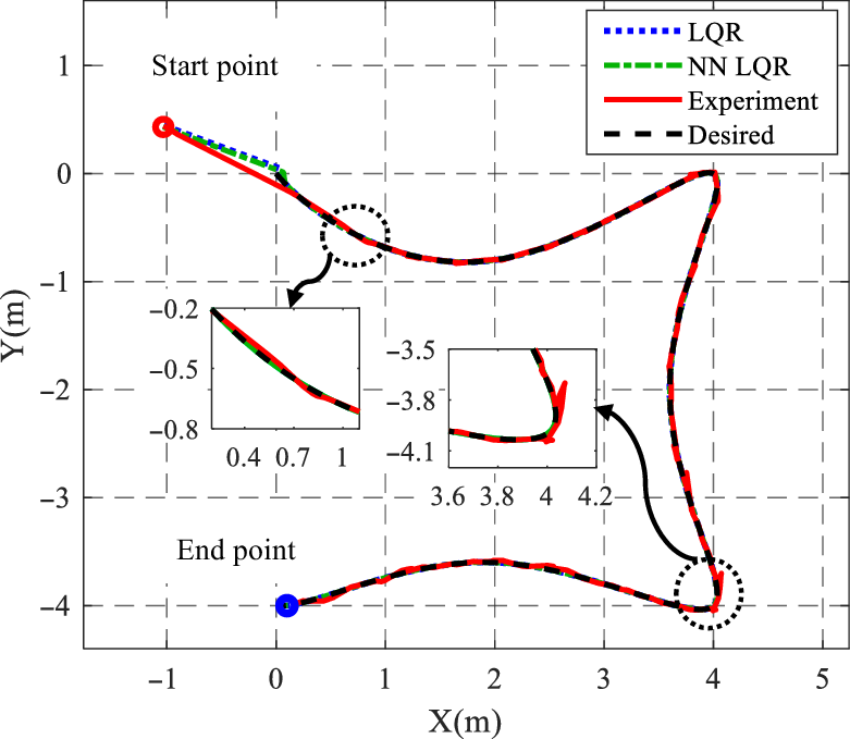
In Fig. 7, the desired path is sigma-shaped, with various curves along the way. Test results in the desired path for simulation test with the LQR controller (LQR), with the neural network (NN LQR), and the path taken by the real four4-WMR with the intelligent controller (Experiment) has been shown. The best Q and R were extracted by trial and error method for the LQR test. However, the path’s information was unfamiliar to the network, but the NN LQR trained network has optimally obtained the best gains, and the robot tracked the path very well. As can be seen, in the experimental test, the path taken by the robot has slight oscillations around the desired path, which is part of the actual system reality.
Path tracking in simulation and experimental test of LQR controller.

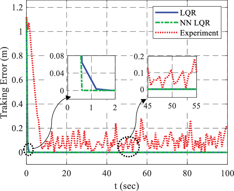
Figure 8 shows the path tracking error, obtained as the least-squares error method of two states x and y as Eq. (15).
 \begin{equation} \textit{Tracking}\; \textit{Error}(k)=\sqrt{\left(x_{c}(k)-x_{ref}(k)\right)^{2}+\left(y_{c}(k)-y_{ref}(k)\right)^{2}} \end{equation}
Tracking error relative to the reference path at each step.

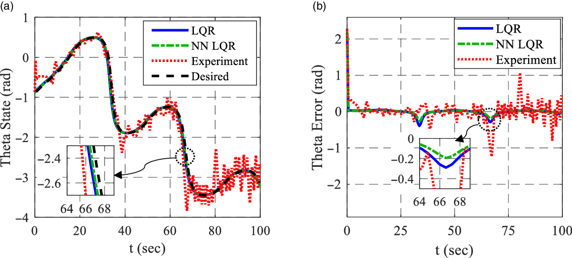
The path error in the NN LQR mode is less than the LQR in the simulation test. However, the path error is generally low in the simulation test due to the parametric solution. To have a better outlook of the difference between the two simulation tests in the linear controller, Fig. 9(a) shows the angle state variable in the considered path, and the difference between the value of this state variable and its reference in each step is referred in Fig. 9(b). As can be seen, this state’s error in the controller with the proposed method is lower, especially in the corners of the path.
(a) Theta state rate in simulation and experimental test. (b). Theta state error in simulation and experimental test.

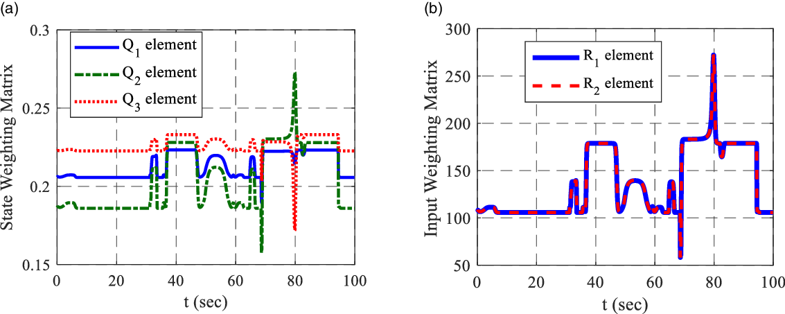
Data obtained graph related to the weighting matrices from the NNLQR controller’s network along the path in form (10a) is related to diagonal elements of the Q matrix, which have been optimally extracted in each step of the path. All three elements are separately extracted in different amounts; however, their changes are in the same rhythm based on network training. Figure 10(b) shows two diagonal elements of the R matrix, which are approximately the same values based on the training.
(a) Three diagonal elements of the Q matrix extracted from the neural network. (b) Two diagonal elements of the R matrix extracted from the neural network.

One of the challenges in using the intelligent control method is the solution time. Mentioning that the proposed method has several advantages, such as reducing tracking error, increasing path convergence speed, and saving time and human energy to select control gains; the intelligent controller solution time under the same conditions has been increased by less than 3% compared to the conventional method, which is not comparable with its advantages.
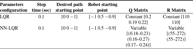
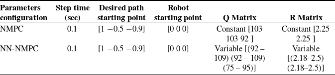
Finally, Table II shows the Q and R matrix elements for two LQR and NNLQR controllers in the same conditions. As can be seen, the amount elements related to the LQR controller are fixed and were the most optimal amount for these conditions.
Compared matrices elements between LQR controllers with the same condition.

5.3. NN-NMPC controller
The NMPC has been used as a nonlinear controller for network training, and more than 18,000 data sets have been collected by solving different paths. Since the number of the network’s inputs, outputs, and data types is the same as the previous network, the number of layers and nodes used in the previous network training has also been applied in this network training. The least-squares error for this network training was
 $0.64\times 10^{-5}$
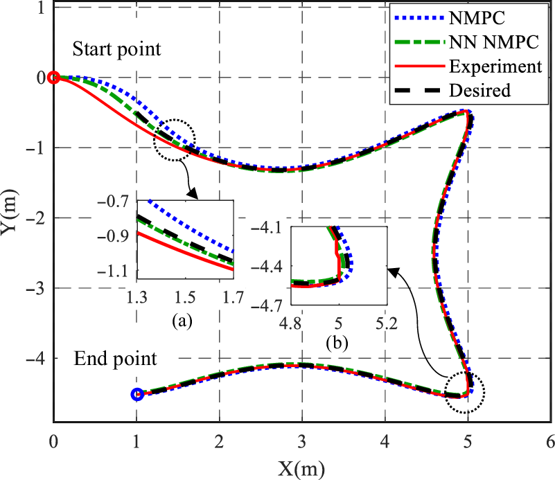
. The simulation code has been prepared in MATLAB, and the sigma-shaped path figures are extracted as Fig. 11. This figure shows the test results in the desired path for the simulation with the NMPC controller (NMPC), with the neural network (NN NMPC), and the path taken by the actual robot with the intelligent controller (Experiment). As can be seen, in the simulation, by applying the neural network and determining the appropriate weighting matrices in each step, the robot got closed to the path with more convergence speed and had lower error than the conventional method, especially in the path’s corners, as shown in Fig. 11(b). In the experimental test, the robot has successfully reached the path and has followed it optimally.
Path tracking in simulation and experimental test of NMPC controller.

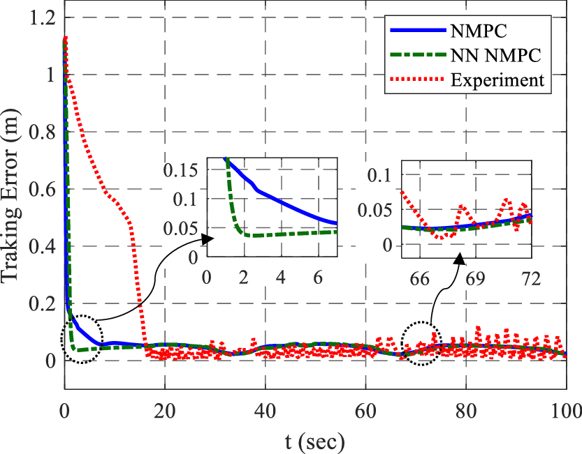
Sampling error and the controller’s endeavor to improve tracking affected the data and caused small oscillations in the experimental test, presented in Fig. 12. However, it is normal and insignificant in the experimental.
Tracking error relative to the reference path at each step.

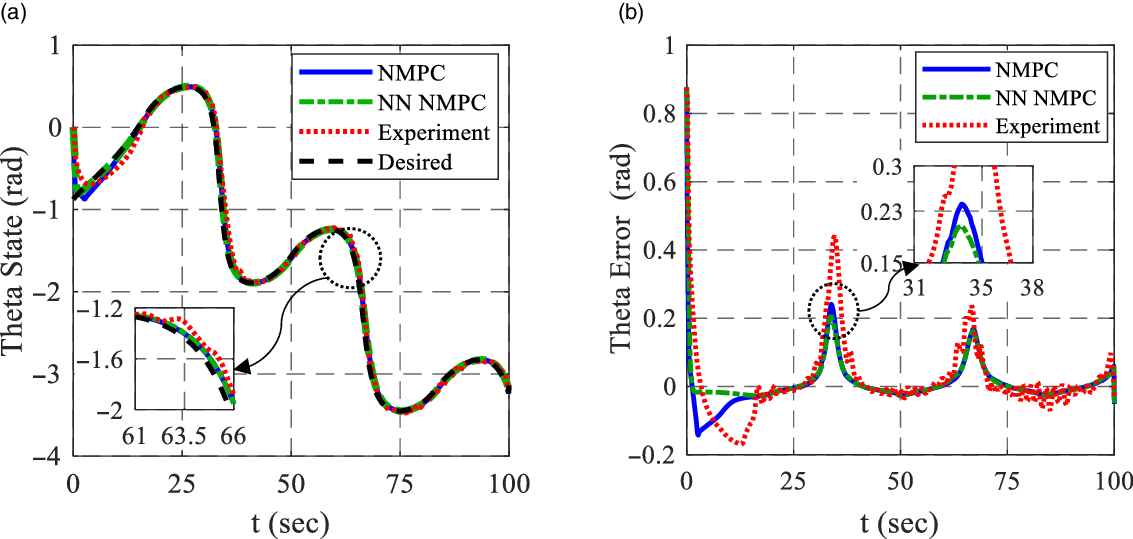
Figure 13(a) shows change rates in the robot body’s rotation angle during solution time. The intelligent controller obtained a better performance with a smaller error than the conventional controller, as displayed in Fig. 13(b).
(a) Theta state rate in simulation and experimental test. (b) Theta state error in simulation and experimental test.

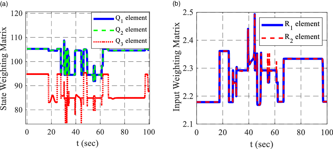
Figure 14(a) shows the diagonal elements of the Q matrix along the considered path, and as can be seen, the optimal gains are extracted at each path step. According to the network training, the two elements
 $Q_{1}$
and
 $Q_{2}$
, which are the coefficient of the two states x and y, have been extracted almost identically, and
 $Q_{3}$
, which is related to the angle state, was different from them but with the same rate of change. Figure 14(b) relates to two elements of the R matrix which
 $R_{1}$
is the coefficient of the robot linear velocity, and
 $R_{2}$
is the coefficient of the robot angular velocity.
(a) Three diagonal elements of the Q matrix extracted from the neural network. (b) Two diagonal elements of the R matrix extracted from the neural network.

Like the previous controller, this controller’s solving time in the proposed method has been measured and compared to the conventional method. Under the same conditions, the intelligent controller solution time has been increased by less than 4%, which is not comparable with its advantages. Also, Table III displays the Q and R matrix elements for two NMPC and NN-NMPC controllers in the same conditions.
Compared matrices elements between NMPC controllers with the same condition.

6. Discussion of results
Generally, with adding the trained networks to controllers, there is no need to extract the weighting matrices by the trial and error method anymore, and the networks have extracted these gains. In addition, as can be seen in the figures, intelligent controllers’ performance is better and optimizer than the usual methods, which work up to 7% optimal in tracking (Fig. 11) and up to 19% better in angle state error (Figs. 9(b) and 13(b)). Controlling the system gets easier and simpler by linearizing it, so the system’s error in tracking the path by a linear controller is less than a nonlinear one in the simulation test that can be found by looking closely at the diagrams. Nevertheless, a nonlinear controller performance in simulation is closer to reality. The actual system operates better and more efficiently with a nonlinear controller due to its nonlinear nature, but the linear controller has more oscillations around the path and less accuracy in following the path. This point can be followed by comparing the experimental tests of two linear and nonlinear models.
7. Conclusion
This paper proposes an intelligence approach based on MLP-NN for the controllers with the cost function. The controller’s performance has been improved, and the path tracking error has been reduced. In addition, the need to spend time and human energy to adjust the weighting matrices has been eliminated. The proposed method can be implemented for all linear and nonlinear controllers with the cost function. A suggested method also causes better performance by entering the calculations of future steps in the extraction of weighting matrices. In order to validate the performance of NN LQR and NN NMPC controllers, the results have been compared with their conventional methods in simulation mode. Also, the experimental test results obtained from the 4-WMR show the excellent performance of the presented method in a real environment. In this case, the trained network obtains the best weighting matrices in each step for any path or starting point selected for each robot, and the controller optimally tracks the path. The intelligent controllers performed up to 7% better than the conventional method in path tracking and up to 19% better in angle state error in corners of the path.
Authors’ contributions
M. H. Korayem and N. Y. Lademakhi conceived of the original idea. This was also discussed with H. R. Adriani, and all authors agreed with this paper’s main focus and idea. The test’s plan was designed by H. R. Adriani and N. Y. Lademakhi, and H. R. Adriani carried out the simulations and the experimental tests under the supervision of M. H. Korayem. The first version of the paper was written by H. R. Adriani and M. H. Korayem, and N. Y. Lademakhi provided critical feedback and helped shape the research, analysis, and manuscript.
Financial support
Professor Korayem funded this study at Iran University of Science and Technology.
Conflicts of interest
The authors declare that they have no conflicts of interest.
Ethical considerations
None.
Appendix A
Theory of MLP-NN
According to the structure of neural networks, the output vector of the whole network is defined as Eq. (A1), assuming that the number of layers of the whole network is N.
 \begin{equation} f_{N}=\varphi _{N}\!\left(W_{N} f_{N-1}+b_{N}\right) \end{equation}
Where the input vector is considered as
 $X=\left[X_{1}X_{2}\ldots X_{n}\right]^{T}$
which n is the number of network inputs and the vector
 $f_{N}=\left[f_{1}f_{2}\ldots f_{m}\right]^{T}$
is the output vector of the whole network, that m is the number of the network’s outputs.
 $\varphi _{N}$
is the last layer activation function,
 $W_{N}$
is the matrix connecting the N-1 hidden layer with the n hidden layer and
 $b_{N}$
is the bias vector for the last hidden layer. In addition,
 $f_{N-1}$
is assumed to be the output of the N-1 hidden layer. in the other word, the output of the neural network with K hidden layer can be extracted in the form of Eq. (A2):
 \begin{equation} f=W_{K}\mathit{\max } \left(0,W_{K-1}\mathit{\max } \left(\ldots max\left(0,W_{1}X\right)\right)\right) \end{equation}