




1. Introduction
Inward-turning intakes have received considerable attention because of their advantages of high compression ratio, high mass capture rate, small wetted area, etc. (Smart Reference Smart1999; Zuo & Mölder Reference Zuo and Mölder2019; Zuo et al. Reference Zuo, Memmolo, Huang and Pirozzoli2019). However, due to the three-dimensional converging geometry of this type of intake, a clear characterization seems to be very challenging; therefore, it is helpful to use simplified models to explore the basic characteristics and mechanisms of the flow. One of the simplest cases might be the shock reflections in axisymmetric converging flows, which can be traced back to as early as the work of Ferri (Reference Ferri1946), which calculated and showed the strengthening of a conical intake shock and formation of a normal shock at the centreline. It has since been well demonstrated that due to the intrinsic effects of flow convergence, a conical converging shock continuously strengthens as it approaches the centreline and can only be finalized by the generation of a central Mach disc (Rylov Reference Rylov1990; Courant & Friedrichs Reference Courant and Friedrichs1999; Hornung Reference Hornung2000; Hornung & Schwendeman Reference Hornung and Schwendeman2001; Isakova et al. Reference Isakova, Kraiko, Pyankov and Tillyayeva2012; Shoev & Ogawa Reference Shoev and Ogawa2019). In recent years, attention has been concentrated on the effects and characteristics of longitudinal/transverse shock curvatures, including theoretical descriptions and inherent mechanisms. Mölder (Reference Mölder2012, Reference Mölder2017a,b,c), after efforts to develop curved shock theory (CST) which relates shock curvatures to gradients of flow properties immediately upstream and downstream of the shock, extended the applications to various cases of doubly curved shock waves. Gounko (Reference Gounko2017) focused on triple-shock configurations with free-stream Mach numbers  $M_\infty = 1.6$ and 2.0, and explored conditions to determine the position and size of the Mach disc. Filippi & Skews (Reference Filippi and Skews2017, Reference Filippi and Skews2018), on the other hand, performed a series of careful and detailed examinations of the effects of internal surface curvature and leading-edge angle on the behaviours of a converging shock wave and the flow behind it, which were also used to validate the aforementioned CST to some extent.
However, to the best of the authors’ knowledge, the majority of previous works were carried out with axisymmetric configurations. From a practical point of view, intake flow is non-axisymmetric in reality. A deviation from the axisymmetric condition may cause fundamental changes in the shock interactions. In the present work, simplified elliptic conical surfaces are chosen as typical non-axisymmetric models, in which the level of the deviation from axial symmetry is quantified with the aspect ratio ( $AR$) between the major and minor axes. Our primary motivation is to present some new features of this near-axisymmetric flow that differ basically from the case of axisymmetric flow and shock structure.
2. Model and methodology
2.1. Description of the model
The schematics of the elliptic conical surfaces are displayed in figure 1, where the local leading-edge radii along the major and minor directions are denoted as  $c$ and
 $d$, respectively. The wall profile of the model can be defined by (2.1):
 \begin{equation} \frac{{{y^2}}}{{{{(c - x\tan {\delta _0})}^2}}} + \frac{{{z^2}}}{{{{(d - x\tan {\delta _0})}^2}}} = 1,\quad 0 \le x \le L . \end{equation}
The x, y and z axes denote the directions along the free-stream, major and minor directions, respectively, and the origin of the coordinates is situated at the centre of the leading-edge plane. To generate converging incident shocks with initially uniform strengths, the models are designed with the same leading-edge angle  $\delta _0 = 10^{\circ }$. The length of all the models is
 $L = 100$ mm. All the models considered in the present work share a common
 $c = 100$ mm, while
 $d$ varies to obtain different ARs (defined as
 $AR = c/d$) on the leading-edge plane. Initially converging near-elliptic shocks are generated immediately at the leading edges of the models, which develop downstream and form longitudinally curved surfaces (see figure 1a). The polar angle
 $\varphi$ is defined as the angle from the major direction to the polar line. The leading edges of the four models with different ARs (
 $AR = 1$, 1.11, 1.25 and 1.43) are shown in figure 1(b), where the leading edges deviate from a circular shape (
 $AR = 1$) with increasing AR.
(a) Schematic of the elliptic conical surface. (b) Leading edges of the elliptic conical surfaces.

2.2. Methodology
The experiments were conducted in the  $KDJB330$ shock tunnel of the University of Science and Technology of China with a free-stream Mach number
 $M_\infty = 6$ (Li et al. Reference Li, Gao, Jiang and Yang2013, Reference Li, Huang, Li and Yang2018; Zhang et al. Reference Zhang, Li, Huang and Yang2019b). The stagnation pressure and temperature of the incoming flow were 1.4 MPa and 830 K, respectively, corresponding to a free-stream unit Reynolds number of approximately
 $4.2\times 10^{6}$ m
 $^{-1}$. The effective experimental time was approximately 20 ms. A schlieren photographic system was employed to visualize the general features of the flow field. The schlieren images were recorded by a camera with a frame rate of 6273 frames per second and an exposure time of 1
 $\mathrm {\mu }$s. A schematic of the experimental model is shown in figure 2(a). To obtain more details of the shock structure, schlieren photographs were taken along both the major and minor directions of the model.
(a) Experimental model. (b) Computational domain.

A three-dimensional Euler solver based on the finite volume method was employed to simulate the flow field as the effects of viscosity and the presence of a supersonic boundary layer were deemed negligible. The Roe flux difference splitting scheme was employed for the approximation of the inviscid fluxes (Roe Reference Roe1981). The convective terms were discretized by a second-order upwind scheme. To capture the shock structures, the total variation diminishing gradient limiter was utilized to avoid spurious numerical oscillations near the shocks (Barth & Jespersen Reference Barth and Jespersen1989). The equation of state for a perfect gas was used, and the ratio of specific heat was 1.4. This solver has been proven reliable in our previous study in which it well captured complex shock structures (Zhang et al. Reference Zhang, Li, Li and Yang2019a). The computational domain is shown in figure 2(b), where four types of boundary conditions were used: inflow, outflow, non-reflecting boundary and solid wall. At the inflow boundary, static conditions and free-stream Mach number were specified ( $M_\infty = 6$,
 $p_\infty = 891$ Pa,
 $T_\infty = 101$ K). At the outflow boundary, the flow quantities were extrapolated from the interior. The computational domain was discretized by hexahedral grids. To capture the shock structures elaborately, the grids were greatly refined in the regions of shock interactions. The numerical solution was considered to have converged when the variation of the pressure near the shock reflection point was kept below 0.1 %, along with the stability of continuity and velocity residual.
The configuration with  $AR = 1$ was chosen as a representative case for numerical validation and grid independence study. Three sets of grids were tested, in which the coarse, fine and dense grids contain
 $1.5\times 10^{7}$,
 $2.1\times 10^{7}$ and
 $2.8\times 10^{7}$ cells, respectively. Accordingly, the grid sizes in the
 $x$ direction are
 ${\rm \Delta} x/L = 2\times 10^{-3}$,
 $1.5\times 10^{-3}$ and
 $8\times 10^{-4}$ near the Mach disc. As shown in figure 3(a), the isodensity lines obtained using the dense grid are superimposed on the experimental schlieren image, which yields a good agreement in terms of shock structures. Moreover, the shock angle of the incident shock near the triple point is extracted for quantitative comparison. The experimental value of 29.8
 $^\circ$ is slightly less than the numerical value of 30.7
 $^\circ$. This minor discrepancy might be induced by the slight deviation of experimental incoming flow from the nominal Mach number of 6 (Li et al. Reference Li, Gao, Jiang and Yang2013, Reference Li, Huang, Li and Yang2018), which does not affect the type of shock reflection near the centreline. The non-dimensionalized pressure distributions along the
 $y/L = 0.06$ line acquired using the three sets of grids are compared in figure 3(b). The results obtained by the fine and dense grids collapse together, indicating a reasonable convergence of grid resolutions. Therefore, the dense grid was used in the present study. The numerical results are validated against experiments in the form of schlieren images, which are discussed in appropriate locations throughout § 3.
Validation of the numerical method. (a) Comparison of shock structures. (b) Grid convergence study.

3. Results and discussion
3.1. Type A shock intersection with formation of a central Mach disc
Figure 4 presents the basic features for  $AR = 1$, the case of axisymmetric flow, as a benchmark sample for later comparison. The experimental schlieren image, the numerical contour of the normalized density
 $\rho /\rho _\infty$ and the schematic of the primary wave patterns are displayed in figures 4(a), 4(b) and 4(c), respectively. As shown, a converging axisymmetric shock (IS), generated by the conical surface, approaches and steepens slightly with increasing strength towards the centreline, which is eventually finalized by a Mach disc (or Mach stem in terms of a two-dimensional view, labelled MS in figure 4c) near the centreline as the termination of the shock strengthening. With the help of close-up views from both experimental and numerical images (figure 4a,b), it is recognized that MS is slightly concave towards the free stream and the shear layers (
 $\varSigma$) emanating from the triple points are inclined towards the centreline and form a converging stream tube.
Experimental and numerical flow features in the symmetry plane with  $AR = 1$:(a) experimental, (b) numerical and (c) schematic.

To quantify the triple-shock configuration shown in figure 4 using shock polars, a post-processing procedure similar to the algorithm adopted by Gounko (Reference Gounko2017) is performed on the numerical results. This post-processing procedure first involves the extraction of a streamline released from  $z/L = 0.041$ (see figure 4b), which is as close as possible to the triple point. As shown in figure 5, point (1) is on the
 $M_\infty$ free-stream shock polar (I-polar) at the location
 $\delta = -21.9^\circ$, which represents the flow of region (1) shown in figure 4(c) in the vicinity of the triple point
 $T$. Then the flow parameters just behind
 $IS$ (i.e. region (1)) along the streamline are used to determine the reflection shock polar (R-polar) originating from point (1), where the positive angles in the shock polars correspond to counterclockwise flow deflections. The intersection points between the I-polar and R-polar, labelled (3) and (5), represent the theoretical solution of the flow states in regions (3) and (5) (see figure 4c), respectively. The theoretical pressure ratio of 41.9 agrees well with the computed value of 41.7 in region (3). Thus, the shock polars can be used to distinguish the type of shock reflection and to quantify the strength of the reflected shock. Note that this type of reflection is categorized as direct Mach reflection (DiMR) according to Ben-Dor's definition (Li, Chpoun & Ben-Dor Reference Li, Chpoun and Ben-Dor1999; Ben-Dor et al. Reference Ben-Dor, Ivanov, Vasilev and Elperin2002; Ben-Dor Reference Ben-Dor2007), since the shear layer converges towards the centreline. In other words, the flow direction behind
 $RS$ is on the same side as the flow behind
 $IS$.
Pressure–deflection polar illustrating flow regions in the vicinity of the triple point with  $AR = 1$.

The non-axisymmetric case starts with  $AR = 1.11$, i.e. a small difference between the major and minor axes. As shown in figure 6, although MS is still located in the central region, the effects of the deviation from axial symmetry are notable. Even though the shock structure in the major plane (figure 6a) resembles that in figure 4, where MS is also concave towards the free stream,
 $IS_1$ is obviously steeper near the triple point. This result is more clearly quantified with the help of the shock polars shown in figure 7, where the
 $R$-polar is determined by extracting the streamline released from
 $z/L = 0.027$. Note that the deflection angle is as high as 26.8
 $^{\circ }$ instead of the aforementioned 21.9
 $^{\circ }$ for
 $AR = 1$. Once again, the theoretical pressure ratio of 41.3 agrees well with the computed value of 41.9 in region (3). Furthermore, the wave configuration in the minor plane exhibits very different behaviours. The MS, in contrast, is now convex facing the incoming flow (figure 6b). The shear layers emanating from the triple points flow away from the centreline and form a diverging stream tube. A comparison between the major and minor planes reveals that there is a DiMR for the former and an inverse Mach reflection (InMR) for the latter. Such a phenomenon is more clearly displayed by the shock polars in figure 7, where the
 $R$-polar is determined by the streamline released from
 $y/L = 0.025$, and the deflection of the shear layer (points (3) and (5)) is located at the right-hand side of the vertical axis. The theoretical pressure ratio of 41.7 agrees well with the computed value of 41.9 in region (3). Interestingly, the deflection angle behind the incident shock in the minor plane is only 15.6
 $^{\circ }$, which is much lower than that of 26.8
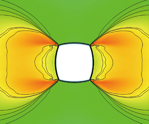
 $^{\circ }$ in the major plane. This result suggests that the deviation from axial symmetry in initial entry condition can be markedly amplified as the flow converges towards the centreline. Figure 8 illustrates the evolution of the shock structure by contours of density superimposed by isodensity lines on several representative cross-sections, which are roughly categorized into two phases. During the first phase, the incident shock converges and strengthens smoothly, through which the circumferential non-uniformity behind the incident shock is enhanced as the cross-section moves downstream, as shown in figure 8(a–c). It is evident that the shock strength at the two ends of the major axis increases obviously faster than the rest of the shock front, which is easily recognized from the higher post-shock density shown in figure 8(c). However, as the flow convergence and shock strengthening go further, the non-uniform strength distribution accumulates to such a critical condition that a kink, or a discontinuous shock strength jump, is inevitably generated. The resulting shock structures are recognized as the second phase once kinks appear on the shock front. As shown in figure 8(d–f), the incident converging shock front collapses into two pairs of arch-shaped shock segments (
 $IS_1$ and
 $IS_2$). It can be easily found that the shock segments around the major direction (
 $IS_1$) are stronger, since not only are their post-shock densities higher but they also travel a longer distance and approach the centreline more closely (see figure 8e) than the shock segments around the minor direction (
 $IS_2$). One more emphasis that needs to be made is about the shock convergence and strength enhancement during the second phase. It is well known that a converging axisymmetric shock wave faces the problem of unlimited amplification as the shock front approaches the centreline, until it is terminated by a Mach disc. Then, a natural question is, how are the characteristics changed if there is a certain level of deviation from the axisymmetric condition? The aforementioned formation of the Mach disc for
 $AR = 1.11$ shows some similarities in incrementation and termination of shock strengthening for the case of axisymmetric flow. However, the enlarged non-axisymmetric shock structures shown in figure 8(d–f) do present at least two fundamentally different behaviours. One behaviour is the formation of two pairs of shock segments that are connected by discontinuous kinks. The other is the suppression effects of these shock segments for further strengthening. As shown in figure 8(d,e), the radii of curvature of the curved shock segments are far larger than their distances to the centreline. This means that when the shock segments converge to the centre, their radii of curvature never shrink to zero. In other words, the shock amplification effects are greatly suppressed with the appearance of these planarized shock segments.
Experimental and numerical flow structures with  $AR = 1.11$. (a) Major plane. (b) Minor plane.

General pressure–deflection polar combination illustrating the shock structures ( $AR = 1.11$). (a) Major plane. (b) Minor plane.

Flow cross-sections at increasing distances from the leading edge ( $AR = 1.11$): (a)
 $x/L=0.2$, (b)
 $x/L=1.0$, (c)
 $x/L=2.0$, (d)
 $x/L=2.46$, (e)
 $x/L=2.49$ and (f)
 $x/L=2.53$.

3.2. Type B shock intersection without a central Mach disc
When  $AR$ increases beyond a certain value, a new type of shock structure is obtained in which the central Mach disc disappears and the incident shocks intersect with each other in a manner of regular reflection. Figure 9 demonstrates the shock structures in the major and minor planes for
 $AR = 1.43$. Although the numerical images agree well with the experimental schlieren images, the complicated structures in the intersection region cannot be determined with only the information provided in figure 9. Thus, a series of cross-sectional structures are displayed in figure 10 to give a better interpretation. It is noticeable from figure 10 that the aforementioned second phase starts earlier for such a large deviation from the axial symmetry condition. Figure 10(c) exhibits two obvious pairs of shock segments, although the segments at the two ends of the major direction are shorter owing to the larger AR. As the incident shocks converge further, the scale of the shorter segments
 $IS_1$ around the major direction soon shrinks to zero (see figure 10d), and the longer segments
 $IS_2$ around the minor direction intersect with each other at shock intersection line 1 (
 $SL_1$) to generate a pair of
 $RS_2$ (see figure 10e). The reflection of
 $IS_2$ can be illustrated by pressure–deflection polars. As shown in figure 11(a), the deflection angle behind
 $IS_2$ determined by a streamline released from
 $z/L = 0.005$ is merely 12.1
 $^{\circ }$, which is lower than that of 15.6
 $^{\circ }$ for
 $AR = 1.11$. The computed value of the pressure ratio in region (3) is 14.4, which agrees with the theoretical value of 14.8.
Experimental and numerical flow structures with  $AR = 1.43$. (a) Major plane.(b) Minor plane.

Flow cross-sections at increasing distances from the leading edge ( $AR = 1.43$): (a)
 $x/L=0.2$, (b)
 $x/L=1.0$, (c)
 $x/L=2.0$, (d)
 $x/L=2.08$, (e)
 $x/L=2.20$ and (f)
 $x/L=2.30$.

General pressure–deflection polar combination illustrating the shock structures ( $AR = 1.43$). (a) Minor plane. (b) Major plane.

An interesting phenomenon that needs to be mentioned is that when the  $RS_2$ pair spreads outwards along the minor direction, as shown in figure 10(e), another pair of lateral inward shock segments is generated around the major direction. This pair of newly generated shock segments is named lateral inward shock (LIS), which spreads inward and reflects regularly at shock intersection line 2 (
 $SL_2$) to generate
 $RS_1$ further downstream (see figures 10f and 9a). The shock polar for the reflection of LIS is shown in figure 11(b), where the
 $R$-polar is determined by the streamline released from
 $y/L = 0.005$. As predicted by the shock polars, this shock reflection elevates the pressure ratio near the centreline to 28.5, which agrees well with the computed value of 28.2. In general, the shock structure of this type of flow field is determined by the reflection of the weak shock segments along the minor direction, and this type of shock structure is termed as type B regular shock intersection.
3.3. Type C critical intersection with coincidence at the centreline
For a critical value of  $AR = 1.25$, the flow features behave somewhat surprisingly, as shown figure 12, where
 $IS_1$ in the major plane and
 $IS_2$ in the minor plane intersect with the centreline almost simultaneously to form a singular point, which is followed by the generation of
 $RS_1$ and
 $RS_2$, respectively. This type of shock structure is specifically termed as type C critical intersection. At least two puzzling questions deserve to be clarified. The first question is: how can a non-axisymmetric shock front manage to converge to a single point? The other question is: why is the inevitable formation of a central Mach disc avoided for such a flow that converges towards the centreline?
Experimental and numerical flow structures with  $AR = 1.25$. (a) Major plane.(b) Minor plane.

For the first question, the answer can be found in the cross-sectional shock structures shown in figure 13. The typical differences in the shock structures compared with the aforementioned two types are the behaviours of the two pairs of shock segments during the shock-converging process. For a low aspect ratio such as  $AR = 1.11$, the stronger pair of shock segments around the major direction approaches closer to the centreline (see figure 8e). For a high aspect ratio such as
 $AR = 1.43$, however, the weaker shock segments around the minor direction reach the centreline earlier (see figure 10). Therefore, there exists a matching condition (
 $AR = 1.25$) under which the two pairs of shock segments (
 $IS_1$ and
 $IS_2$) reach the centreline simultaneously (see figure 13e). For the second question, we suggest that the principal reason is the collapse of the initially smooth shock front, which suppresses the shock amplification effects. For the present case, when the two pairs of shock segments (
 $IS_1$ and
 $IS_2$) intersect at the centreline, they behave more like two pairs of planar shocks that regularly intersect with each other from two orthogonal directions.
Flow cross-sections at increasing distances from the leading edge ( $AR = 1.43$): (a)
 $x/L=0.2$, (b)
 $x/L=1.0$, (c)
 $x/L=2.0$, (d)
 $x/L=2.20$, (e)
 $x/L=2.35$ and (f)
 $x/L=2.40$.

3.4. Discussion
From the results described previously, it can be concluded that the amplification effects of the deviations from axial symmetry are notable, which cause fundamental changes in the shock reflection patterns. Therefore, it is valuable to seek the mechanism for the non-uniform development of the circumferential shock strength and its converging characteristics. For a steady supersonic flow, the CST proposed by Mölder (Reference Mölder2012) relates the shock curvatures and flow convergence in planar, axisymmetric flow and the meridional symmetry plane of three-dimensional flows (Emanuel Reference Emanuel2018). Thus, the CST is adopted to evaluate the effects of flow convergences in the major and minor planes of the present converging near-elliptic shocks.
As shown in figure 14(a), for a stationary curved shock element, the shock traces in the flow and flow-normal planes are named a–a and b–b, respectively. The shock curvatures along the two traces are termed the flow-plane curvature  $S_a$ and transverse curvature
 $S_b$, respectively. As shown in figure 14(b), at the leading edge of the elliptic conical surface, the incoming flow is deflected by an angle
 $\delta _0$, and the corresponding shock angle is
 $\theta$ (i.e. an obtuse angle for the internal flow) (Mölder Reference MölderReference Mölder2017c). Because of the flow convergence effects, the shock traces in the major and minor planes that are denoted
 $IS_1$ and
 $IS_2$, respectively, steepen towards the centreline and a doubly curved shock front (i.e.
 $S_a \neq 0$ and
 $S_b \neq 0$) is therefore formed. Note that the internal surface of the elliptic conical surface is straight in the flow plane, and thus the streamline curvature at the internal surface is fixed to zero. For this specific flow, the CST reduces to a simple form in which the normalized pressure gradient on a streamline (i.e.
 $P_2$ in the original CST (Mölder Reference Mölder2012)) is proportional to
 $S_b$ and the coefficient of the proportionality is only determined by the local shock angle and
 $M_\infty$ (Mölder Reference Mölder2017c). In other words,
 $S_b$ is responsible for the flow convergence effects behind the present doubly curved shock. Moreover, it is determined that
 $S_b$ for
 $IS_1$ and
 $IS_2$ at the leading edge is given by
 $S_{b_1} = -c \cos {\theta }/{d^2}$ and
 $S_{b_2} = -d \cos {\theta }/{c^2}$, respectively, which are derived from Meusnier's theorem in differential geometry (Toponogov Reference Toponogov2006). Consequently, the ratio of
 $P_2$ induced by flow convergence in the major and minor planes is given by
 $S_{b_1}/S_{b_2} = AR^3$, which means that the shock strengthening in the major plane is faster and the non-uniformity along the circumferential direction is more significant with increasing
 $AR$.
Schematic of the doubly curved shock. (a) Shock element adapted from Mölder (Reference Mölder2012) and Filippi & Skews (Reference Filippi and Skews2017). (b) Shock traces in the meridional planes of symmetry.

To quantitatively demonstrate the non-uniform shock strengthening, the strengths of the shock fronts are analysed with the help of numerical results. Figure 15(a) presents the evolution of the circumferential shock strengths for  $AR = 1.11$ at different cross-sections, where
 $\varphi = 0^{\circ }$ and
 $90^{\circ }$ represent the major and minor directions, respectively. At the cross-section near the leading edge (see
 $x/L = 0.2$ in figure 15a), the shock strength presents little non-uniformity along the circumferential direction. However, the shock front around the major direction strengthens faster than the shock front around the minor direction as the cross-section moves downstream (see
 $x/L = 1$, 2 and 2.3 in figure 15a), which supports the aforementioned theoretical prediction. The increase in the circumferential non-uniformity finally develops into a sharp jump in the shock strength (see
 $x/L = 2.46$ and 2.49 in figure 15a), which corresponds to the formation of two pairs (i.e. strong and weak) of shock segments (see figure 8 for a combined impression). For a better understanding of the streamwise evolution of the circumferential non-uniformity before the shock collapse, the ratios of the shock strength of
 $IS_1$ (
 $p_{IS_1}$) to that of
 $IS_2$ (
 $p_{IS_2}$) for different
 $AR$s are compared in figure 15(b). The non-uniformity is much more severe with increasing
 $AR$, which presents favourable support for the aforementioned theoretical prediction that the non-uniform shock strengthening is sensitive to the value of
 $AR$. Note that
 $IS_1$ and
 $IS_2$ converge towards the centreline from different off-centre distances (
 $c$ and
 $d$) along with the enlarged differences in the shock strengths, which sets up a competition between the smaller off-centre distance of weaker
 $IS_2$ and the faster shock strengthening of
 $IS_1$ with a larger off-centre distance. This competition results in fundamental changes in the shock interaction patterns compared with the axisymmetric case, which suggests a mechanism for the formation of the present three types of shock interactions.
Circumferential shock strength during the converging process. (a) Different cross-sections for  $AR =1.11$. (b) Different aspect ratios.

4. Conclusions
The shock contraction behaviours in elliptic conical surfaces are investigated by a combination of experiments and numerical simulations at Mach 6. The influence of AR on the evolution of the converging near-elliptic shock is analysed, three types of shock interactions are identified and the underlying flow mechanisms are discussed.
It is revealed that the non-uniform flow convergence effects induced by the local shock transverse curvature strengthen the converging near-elliptic shock with increasing non-uniformity along the circumferential direction, which results in fundamental changes in the shock interaction patterns compared with the axisymmetric case. In general, the initially smooth shock front around the major axis strengthens and approaches the centreline faster, while the shock front around the minor axis strengthens and approaches the centreline slower. During this process, the initially smooth shock front evolves and collapses into a strong pair (major direction) and a weak pair (minor direction) of shock segments, which propagate towards the centreline with different intensities and scales (off-centre distances). For an elliptic conical surface with the same leading-edge angle of  $10^{\circ }$, three types of shock interactions are observed depending on the value of AR. It is determined that when AR is below 1.25, faster shock strengthening around the major direction dominates, and a type A Mach reflection is therefore formed. As AR increases beyond 1.25, the weaker shock segments around the minor direction reach the centreline first, and a type B regular shock reflection is generated. Between these two types of shock reflections, a type C critical intersection pattern is formed at
 $AR = 1.25$, which is characterized by the nearly synchronous arrival of the two pairs of shock segments from the minor and major directions at the centreline. This study provides fundamental insight into the complex shock interactions in near-axisymmetric aerodynamic applications.
Acknowledgements
This work was supported by the National Natural Science Foundation of China (grant nos. 11872356, 11772325 and 11621202).
Declaration of interests
The authors report no conflict of interest.



