Introduction
Over the last few years, wireless applications have grown exponentially with many connected objects. This growth requires many advancements in communication systems with high data rate. Communication systems operating at millimeter-wave frequencies can satisfy the need for high channel capacity. These systems are attracting researchers in the field of development and manufacture of antennas, filters, among other subjects.
Although the microstrip antennas have some drawbacks such as low efficiency, low power, and a very narrow frequency range [Reference Balanis1, Reference Economou and Langley2], their benefits outweigh their disadvantages as they display a myriad of conveniences among which are their ease of installation, small size, low weight, low cost, and compatibility with flat surfaces. Furthermore, there are methods that can be employed to increase their gain and efficiency, such as antenna arrays [Reference Awida and Fathy3], electromagnetic band gap structures [Reference Han, Song, Zhu and Sheng4], superstrate layers [Reference Hadi, Sandhagen and Bangert5, Reference Gu, Liao, Xue and Che6], and substrate-integrated waveguide (SIW) technology. Merging such kinds of antennas with the SIW technology can be used to combine the performance [Reference Hong7, Reference Cheng and Fan8]. SIW technology might be defined as flat structures fabricated in a way that rows of plated holes connect the top and bottom faces in a periodic manner. Because of its ease of fabrication, its small size, light weight, reliability, and low cost, this technology is preferred. In addition, the flat shape of the SIW allows the integration of passive and active components, so that it is incorporated onto the same plate.
The use of SIW technology has a direct effect on improving the performance of microstrip antennas in terms of gain and efficiency [Reference Abdel-Wahab and Safavi-Naeini9, Reference Awida and Fathy10]. To take advantage of the improved properties of the microstrip patch antenna based on SIW and to enhance the fundamentally limited characteristics such as narrow bandwidth, several techniques have been proposed such as substrate elimination [Reference Yun, Kim and Nam11, Reference Yeap and Chen12], and mode stacking [Reference Mukherjee, Biswas and Srivastava13–Reference Shi, Liu and Long16], and tunability [Reference Costantine, Tawk, Christodoulou, Chen, Liu, Nakano, Qing and Zwick17].
A reconfigurable antenna can be used to cover a wide band. In fact, several methods for adding reconfigurability exist, including the use of Varactor diodes [Reference Sboui, Machac and Gharsallah18, Reference Sboui, Machac and Gharsallah19], Pin diodes [Reference Choi, Park, Youn, Hwang, Seong, Whang and Hong20], RF-MEMS microelectromechanical systems [Reference Rebeiz21, Reference Khaira, Singh and Mansour22], and agile materials [Reference Dash and Patnaik23–29].
Nevertheless, the use of diodes or RF-MEMS for tuning purposes at millimeter-wave frequencies poses implementation challenges due to the small size of the antennas and their high cost. However, the use of agile materials is a promising method.
In [Reference Kim and Oh25], an aperture-coupled microstrip patch antenna that uses liquid crystals for a reconfigurable resonance frequency is presented. The tunable frequency range is from 26.9 to 30.08 GHz, with bandwidth and efficiency reaching Δfr = 3.18 GHz and 83%, respectively. The measured gain reaches 3.9 dBi. In [Reference Choi, Park, Youn, Hwang, Seong, Whang and Hong20], a planar folded slot antenna includes PIN diodes as a tuning technique, the tunable frequency is changed from 27.65 to 29.1 GHz, the bandwidth obtained is Δfr = 1.45 GHz, and the maximum gain value reached is 6.4 dBi. In [Reference Tan, Wu, Wang and Poo26], a ferrite loaded SIW antenna tuned with a magnetic field, the resonant frequency can be adjusted from 8.98 to 9.74 GHz, Δfr = 760 MHz, and the measured gain reaches 5 dBi. In [Reference Tan, Wu and Poo27] an SIW slot antenna loaded with ferrite slabs is demonstrated. The frequency and polarization can be tuned by varying the applied magnetic field. The tunable frequency range is >8.1% in the lower frequency band (8.98–9.74 GHz) and 5.5% in the upper frequency band (9.98–10.54 GHz). The antenna maximum gain reaches 6.34 dBi.
This work presents a new design of a microstrip SIW patch antenna for tunable resonant frequency based on the use of nematic liquid crystals (K15). The first section of this paper deals with the design of the proposed antenna's size optimization. According to the simulation results, a good reflection coefficient S 11 and an appropriate realized gain are presented. The second part covers the process of making the proposed antenna reconfigurable by using nematic liquid crystals (K15), creating a cavity in the ground plane where liquid crystal is injected. In addition, a new approach where the resonant frequency is varied using magnetic field created by two magnets is also discussed. The third part highlights the measurement results of the fabricated antenna and the comparison with the simulation.
Properties of liquid crystals
Liquid crystal is a dielectric material that is commonly used by the microwave community in the nematic state due to its ability to change its dielectric properties (permittivity) by applying an electric or a magnetic field. Changing the direction of the liquid crystal molecules by an electric or magnetic field automatically changes the dielectric permittivity. Therefore, injecting the LC into an antenna between the top face and its ground plane is the key to reaping the benefits of the liquid crystal by adjusting the resonance frequency. In the literature, such control is usually performed by applying an electrical field. In this work, such variation is done by applying a magnetic field. This method is adapted because of the possibility to tune the mentioned parameters by different means, which could be in the form of electrically powered magnets, permanent magnets, which for the latter does not require any power, and in such case can be varied by simply readjusting the distance between them and the structure. This is an advantageous novel method that is not found in literature.
In this study, the liquid crystal molecules will be oriented through a magnetic field, which is equivalent to using an electric field. In [Reference Oswald and Pieranski30] the critical magnetic field must be reached (H c = 1000 Oersted) in order to generate the Frederiks transition in a nematic liquid crystal sample with a thickness of 0.1 mm characterized by positive anisotropy (Δɛ = ɛ|| − ɛ⊥ > 0). As the volume of the sample thickens, the required critical magnetic field decreases. In this paper, the amount of the nematic liquid crystal (K15) used is 0.3 mm thick. Furthermore, two magnets are used to create a magnetic field with a strength of 1188 Oersted at a distance of 6 mm from the sides of the liquid crystal layer to ensure that the liquid crystal molecules settle parallel to the applied field.
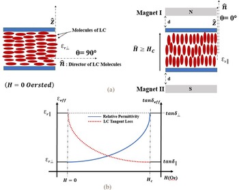
In this work, the magnets are positioned at a distance of d = 6 mm on the lateral sides of the antenna to reach the desired magnetic field strength to make the liquid crystal molecules take positions parallel to the applied field and to reach the parallel permittivity ɛ⫽, as shown in Fig. 1(a). To eliminate the magnetic field (H = 0 Oersted), and thus obtain the perpendicular permittivity ɛ⊥ of the liquid crystal (K15), it is sufficient to remove the two magnets. In this work, the weight of the magnets is not considered.
(a) Configuration of the parallel and perpendicular permittivity. (b) Evolution of the effective relative permittivity and loss tangent in general case of liquid crystal as functions of the applied bias magnetic field. [Reference Oswald and Pieranski30–Reference Yaghmaee, Karabey, Bates, Fumeaux and Jakoby32].

Anisotropy is an important property that characterizes all liquid crystals, it is defined as the difference between the parallel and perpendicular permittivity cited in [Reference Oswald and Pieranski30] and given by the relationship below:

Thus, the following equations represent the perpendicular permittivity and the parallel permittivity mentioned in [Reference Yang and Wu31, Reference Yaghmaee, Karabey, Bates, Fumeaux and Jakoby32] (Table 1):


The characteristics of the nematic liquid crystal (K15) [Reference Martin, Laurent, Person, Le Roy, Perennec, Gelin and Huret33]

Antenna design
Proposed SIW microstrip patch antenna without liquid crystal
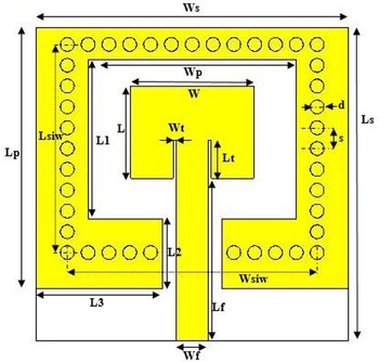
Antenna substrate parameters such as thickness, relative permittivity, and loss tangent are critical to the performance of millimeter-wave antennas. The topology of the new SIW patch antenna, shown in Fig. 2, has been inspired by the reference [Reference Awida and Fathy10, Reference Luo, Wang and Zhang34, Reference Kumar, Saravanakumar and Raghavan35].
Design of the proposed SIW microstrip patch antenna.

In fact, the primary role of the SIW cavity at the back of the patch antenna is to effectively suppress surface wave spurious signals, thereby confining the energy beneath the patch. In this perspective, it is essential to study the leakage characteristics of SIW cavities as a closed resonant structure before they can be added to antenna topologies with open radiation. Here, we address the design issues for the implementation of SIW cavities, including the effect of the via hole diameter and spacing, by identifying suitable designs. Indeed, in order to design the SIW cavity patch antenna presented in Fig. 2 and to determine its most important design parameters, we used the classical equations (4)–(8) cited in [Reference Balanis1] to determine the length and width of the rectangular radiative patch, the latter is supported by an SIW cavity designed using equations (9)–(11) cited in [Reference Sboui, Machac and Gharsallah18, Reference Pozar36, Reference Entesari, Saghati, Sekar and Armendariz37] in the fundamental electrical transverse mode TE110. Metallized vias of diameter d = 0.4 mm and the distance between two vias s = 0.6 mm, which satisfies the conditions (12)–(14) cited in [Reference Deslandes and Wu38], were used to construct an SIW cavity in the planar substrate to form a shield cavity around the patch element. The patch is placed on one side of the substrate. The SIW cavity is formed using four rows of metallized vias, in order to obtain a behavior similar to a classic metal cavity. The operating frequency selected for the antenna design was 28 GHz, a 0.41 mm-thick substrate of Rogers RT4003C type with permittivity ɛr = 3.55 is used. The antenna is connected by a 50 ohm microstrip line. The geometric parameters of the proposed antenna are shown in Fig. 2 and listed in Table 2.
Dimensions of the proposed SIW microstrip antenna

The width of the patch w is calculated using the equation given below:

where f c is the center frequency, c the speed of light, and ɛr is the relative permittivity.
ɛreff is given by the following equation:

where h is the thickness of the dielectric substrate.
ΔL, the extended incremental length of the patch, can be calculated using the equations given below:

The effective length of the patch can be determined by the following equation:

The actual length of patch Lpatch can be determined by the following equation:

The SIW cavity operates in the fundamental electrical transverse mode TE110. The relation between the operating frequency and the length and width of the cavity is revealed by relations (9)–(11) given in [Reference Sboui, Machac and Gharsallah18, Reference Pozar36, Reference Entesari, Saghati, Sekar and Armendariz37]:


The diameter of the interconnecting via (d) and the spacing (s) between them must meet the following conditions [Reference Deslandes and Wu38]:


At this stage, simulation of the antenna is conducted to determine its performances in terms of reflection coefficient and realized gain before adding the liquid crystal, which is done in the second section with the prototype.
The proposed antenna design without the liquid crystal is shown in Fig. 2. The simulation obtained reflection coefficient plot of the antenna and the gain pattern realized without liquid crystal are presented in Figs 3 and 4, respectively.
Simulated reflection coefficient of proposed SIW microstrip antenna without liquid crystal.

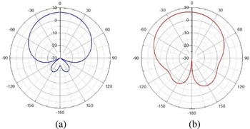
The simulated realized gain patterns of the proposed SIW microstrip antenna at 28.14 GHz. (a) E-plane (phi = 0°). (b) H-plane (phi = 90°).

The proposed antenna without liquid crystal provides |S 11|> + 10 dB impedance matching throughout a bandwidth ranging from 27.66 to 28.61 GHz, corresponding to a wide bandwidth of 950 MHz with a center resonant frequency equal to 28.14 GHz. This value is sufficient for 5G operations.
Figure 3 illustrates a good reflection coefficient S 11 equal to −31 dB at the resonance frequency 28.14 GHz, and a wide bandwidth approximately equal to 1 GHz.
Figure 4 shows the realized gain pattern polar plot which is directional in the E-plane (phi = 0°) and also directional in the H-plane (phi = 90°) at the resonant frequency of 28.14 GHz with a maximum value of 6.88 dBi and directivity value of 7.53 dBi. In addition, the proposed antenna exhibits excellent radiation efficiency of nearly 91.40% at the resonant frequency.
The proposed antenna performs well without the liquid crystal. In the next section of this manuscript, a parametric study is performed to determine the best location to inject the nematic liquid crystal between the radiative patch and the ground plane to establish reconfigurability.
Proposed SIW microstrip patch antenna loaded with liquid crystal
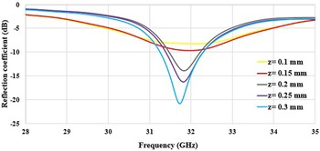
As mentioned in the introduction, injecting the liquid crystal into an antenna between the top face and the ground plane is the key to exploiting its advantages by adjusting the resonant frequency [Reference Kouki, Sboui and Latrach28, 29, Reference Yang and Wu31, Reference Yaghmaee, Karabey, Bates, Fumeaux and Jakoby32]. In this context, the position of the first layer of the liquid crystal should be limited only by the via of the SIW cavity. Moreover, a parametric study was carried out to determine the dimension of the optimal position for the injection of the liquid crystal, which allows a good adjustment of the reflection coefficient of the antenna. During the parametric study, it was found that the thickness of the LC layer has a significant effect on the matching level of the antenna, as shown in Fig. 5.
Reflection coefficient S 11 as a function of the thickness of the liquid crystal layer.

Finally, the liquid crystal layer is placed under the patch to obtain the following dimensions: (LLC = 4 mm, WLC = 4.4 mm, z = 0.3 mm) (Fig. 6).
Design of SIW microstrip patch antenna loaded with nematic liquid crystal (K15).

Measured and simulated results discussion
Frequency tunability
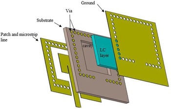
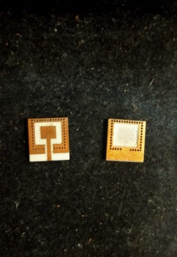
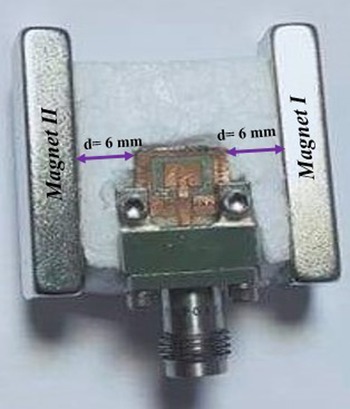
The fabricated antenna prototype is shown in Fig. 7, a conceptual overview of the SIW antenna is shown in Fig. 8, and the fabricated SIW antenna loaded with nematic liquid crystal K15 is shown in Fig. 9. The reflection coefficient of the fabricated SIW antenna loaded with liquid crystal (K15) is measured in free space.
Fabricated prototype of the proposed SIW antenna.

Conceptual overview of SIW antenna loaded with nematic liquid crystal K15 under bias magnetic field created by two magnets.

Fabricated SIW antenna loaded with nematic liquid crystal K15 under bias magnetic field created by two magnets.

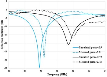
After adding a liquid crystal layer (K15) to the antenna without applying magnetic field (H = 0 Oersted, the perpendicular permittivity of the liquid crystal is therefore ɛr ⊥ = 2.72), the simulation results obtained in Fig. 10 show that the resonant frequency increases from 28.14 to 31.716 GHz with reflection coefficient |S 11| = 20.7 dB while the measured results show that the resonant frequency reaches 32 GHz with |S 11| = 15.86 dB.
Simulated and measured reflection coefficient for different LC permittivities.

The simulation results show that the fabricated antenna loaded with liquid crystal (K15) provides good impedance matching |S 11| > 10 dB when the magnetic field created by two magnets located at 6 mm from both sides of the antenna (Figs 8 and 9; H = 1188 Oersted, the parallel permittivity of liquid crystal ɛr ‖ = 2.9) with the resonant frequency reaching 29.907 GHz at which the reflection coefficient is |S 11| = 34.72 dB. The measured results show that the resonant frequency is at 30.191 GHz with |S 11| = 28.46 dB.
The simulated tunable frequency varies from 29.907 to 31.716 GHz while the measured tunable frequency varies from 30.191 to 32 GHz. In both cases, the tunable frequency varies in a margin of Δfr = 1.809 GHz. The proposed SIW antenna loaded with LC provides good impedance matching |S 11| > 11 dB throughout the whole tuning range.
The measured results are in good agreement with simulation, with just a shifting of 284 MHz resulting from minor fabrication and dielectric characteristics uncertainties, and port losses which are not considered in the simulation.
Radiation performance
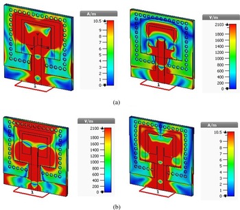
Figure 11 shows the simulated electric and magnetic field distributions for the proposed antenna loaded with liquid crystal at the resonant frequency, in the presence and absence of the applied magnetic field (H = 0 Oe; H = 1188 Oe). The colors representing the field distribution on a logarithmic scale range from dark blue (low density) through green and yellow to red (high density). The variation of the E and H field distribution between Figs 11(a) and 11(b) is related to the variation of the relative permittivity of the liquid crystal. Indeed, the presence of the applied magnetic field H = 1188 Oe is reflected in the change of the relative permittivity of the liquid crystal layer used from 2.72 to 2.9, which is the influencing parameter for varying the resonance frequency.
Electric and magnetic field distributions at resonant frequency.

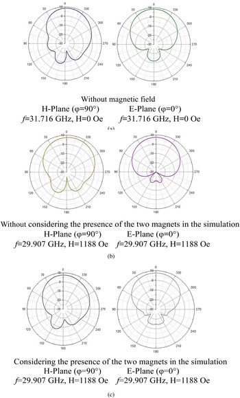
Figure 12 illustrates the realized gain pattern of the SIW antenna loaded with liquid crystal (K15) in three different scenarios.
Simulated realized gain patterns versus frequency at H = 0 Oe and H = 1188 Oe.

The first scenario is when the liquid crystal permittivity is equal to ɛr ⊥ = 2.72 and no field is applied at the resonant frequency f = 31.716 GHz, as shown in Fig. 12(a). In the second scenario, the liquid crystal permittivity reaches ɛr ‖ = 2.9 and the applied magnetic field is H = 1188 Oersted at the resonant frequency f = 30.191 GHz, as shown in Fig. 12(b). It can be concluded that the antenna generates an approximately directional radiation pattern for the two main planes E-plane (φ = 0°) and H-plane (φ = 90°) in simulation. In the third scenario, the same conditions prevail as in the second scenario, but considering that the two magnets are placed at a distance of 6 mm in a field area close to the antenna. It can be seen from Fig. 12(c) that the simulated radiation pattern is approximately the same when the two magnets are not considered (Fig. 12(b)). This can be explained by the role of the rows of metallized vias, which form a shield that limits the generated radiation pattern. It can be also noted that the realized gain patterns are almost identical while the antenna is varied in terms of frequency.
In Fig. 13, the maximum realized gain of the SIW patch antenna at the resonance frequency f = 31.716 GHz (H = 0 Oe; ɛr ⊥ = 2.72) reaches a value of 9.07 dBi and the efficiency reaches 94.4%. Even if H = 1188 Oe is applied, resulting in ɛr ‖ = 2.9 at the resonant frequency f = 30.191 GHz, the realized gain reaches 7.61 dBi and the efficiency 93%, considering the two magnets placed 6 mm apart close to the antenna. This roughly confirms the predicted results without considering the magnets (the realized gain reaches 7.89 dBi and the efficiency 93.15%). It can also be noted that the realized gain decreases from 9.07 dB to 7.61 dBi by applying the magnetic field.
Realized gain versus frequency at H = 0 Oe and H = 1188 Oe.

Table 3 illustrates the performance of the proposed SIW antenna compared to the performance of [Reference Choi, Park, Youn, Hwang, Seong, Whang and Hong20, Reference Kim and Oh25, Reference Tan, Wu, Wang and Poo26, Reference Tan, Wu and Poo27] that use different tunable techniques presented in literature. The proposed SIW antenna loaded with liquid crystal (K15) has the highest gain value (7.61 dBi, 9.07 dBi) and a height radiation efficiency reaching (93%, 94.4%), in simulation both are better than the mentioned works. The measured reflection coefficient S 11 parameter is peaking at −28 dB, better than those of the previously mentioned works. The simulation and measurement results of the conducted work solidify the use of liquid crystals in millimeter waves dedicated to 5G applications. The proposed antenna is characterized by its simplicity and compactness. It also delivers a good range of tunable frequency and excellent gain and efficiency. The proposed SIW antenna loaded with liquid crystal (K15) is thus suitable for many 5G and satellite communication systems.
Comparison of the proposed tunable SIW antenna with works presented in literature

Conclusion
In this work, a novel magnetically tunable microstrip patch antenna based on SIW technology loaded with nematic liquid crystal (K15) is presented. To obtain frequency agility, the nematic liquid crystal is injected in an optimal location between the radiative patch and the ground plane. The tunable frequency is obtained by exploiting a new method that consists in applying a magnetic field created by two magnets. The proposed method of generating a magnetic field by permanent magnets is due to simplicity, since these magnets have a fixed shape and do not need a source to generate a magnetic field. Additionally, if there is a need to modify the strength of such field, mechanical solutions can be adopted to change the placement of the magnets. As a perspective, another method can be suggested to control the magnetic field and therefore the frequency variation through electrical excitation. One magnetic circuit of interest is the coils of Helmholtz [Reference Podaru, Moore, Dani, Prakash and Chikan39]. The resonant frequency varies from 30.191 to 32 GHz presenting a margin of ΔFr = 1.809 GHz. The peak gain reaches simulated values of 7.61 and 9.07 dBi. The use of liquid crystals in reconfigurable antennas is promising at millimeter-waves dedicated to 5G applications and satellite communication systems. The presented method is characterized by its simplicity not only in the making process but also in tuning the resonant frequency of the antenna. Unlike previously adapted methods, it does not necessarily require external powering to tune the frequency, and can be in fact based on different approaches.
Financial support
This research received no specific grant from any funding agency, commercial or not-for-profit sectors.
Conflict of interest
None.
 Adel Kouki was born in Tunis, Tunisia. He received the engineer degree in applied science to weapons from the military academy, Tunisia in 2013. He is currently working toward the Ph.D. degree in electrical engineering at the Faculty of Sciences of Tunis ElManar University, Tunisia. His main research interests lie in the reconfigurable antennas design for wireless and 5G application.
 Fakher Sboui was born in El Hamma Gabes, Tunisia. He received the Ph.D. degree in electrical engineering from the Faculty of Sciences of Tunis, Tunisia in 2019. His main research interests lie in the reconfigurable antennas design and the SIW technology.
 Lassad Latrach was born in Tunis, Tunisia, on October 16, 1977. He received the B.S.E.E. and M.S. degrees in electrical engineering from the University of Tunis ElManar, in 2004 and 2006, respectively, and the Ph.D. degree in electronics systems high frequency from the Faculty of Science, Tunis ElManar University, Tunisia, in 2010. Between 2010 and 2016, he was an assistant professor with the National School of Computer Sciences, University of Manouba, Tunisia. From 2016 to date, he is a professor in the same department. His current research interests include design and modeling of high-frequency circuits for communications applications.