1. Introduction
One of the main goals of a wheeled-legged manipulator (WLM) is to reach diverse points in complex environments. Because surfaces vary in their support for movement, the manipulator must be designed for adaptability to different terrains. Articulated legs allow body height adjustment and improve task performance in challenging conditions. The manipulator arm further extends the workspace, and with additional degrees of freedom, it can perform a wider range of operations. In contrast, traditional manipulators are either stationary or limited to simple bases, restricting their adaptability. A WLM, however, provides greater flexibility through body motion, height adjustment, and rotational capability, offering a much larger workspace and the ability to follow diverse paths effectively.
In previous works, Nikseresht et al. investigated a wheeled-legged robot (WLR) capable of operating under different motion conditions. They highlight the increasing use, diverse structures, and various applications of such robots, emphasizing the need for further study. Their study concentrates on analyzing the dynamics and kinematics of the WLR and studying its movement and performance [Reference Nikseresht, Korayem and Toorani1]. They develop a kinematics formulation for a WLM with a wheel slippage assumption. They utilize the reinforcement learning-based Deep Deterministic Policy Gradient PID controller for a WLM [Reference Asadi, Nikseresht and Korayem2]. They also concentrate on the WLR’s dynamic and kinematic modeling, considering the impacts of both kinematic and dynamic slip. Also, the robot’s dynamic formulations are obtained through the Gibbs–Appell method. Since defining wheel slip is complex and depends on factors such as posture, velocity, and surface characteristics, they employ a vision-based pose estimation method to quantify slippage [Reference Korayem, Nikseresht and Asadi3]. Numerous recent research efforts have concentrated on advancing WLM mechanisms, as they play a crucial role in enhancing the robot’s efficiency, flexibility, and functionality to navigate obstacles. Accordingly, Du et al. examined a WLM and developed a dynamic controller to generate full-body robot behaviors. To track the central motion of the robot body, they developed a dynamic and kinematic model of the wheeled-legged mechanism and a motion model based on movement acceleration. They proposed a recursive dynamic model concept that facilitates the control and simulation process of the robot. Placing a manipulator on such robots has significantly expanded their applications, enabling the implementation of various controllers for simultaneous control of both the robot’s movement and the arm dynamics [Reference Du, Fnadi and Benamar4]. Lagnemma et al. designed and constructed the SRR WLM, capable of adapting its dynamic and kinematic setup based on the terrain. By utilizing a quasi-static technique, they enhanced the robot’s stability. Also, they introduced modifications to the kinematic platform to enhance efficiency on irregular terrains [Reference Iagnemma, Rzepniewski, Dubowsky, Pirjanian, Huntsberger and Schenker5]. Cordes et al. developed a motion model for the Sherpa WLM. Its movement system consists of four legs attached to four wheels, offering a complete set of six degrees of freedom per wheel-leg assembly. They developed an active suspension system for the robot’s body, incorporating a gear-locking feature that allows height maintenance without active motor movement, thus improving manipulator stability for object handling. This enables energy-efficient and highly flexible wheeled movement over obstacle-rich terrains. They also considered kinematic constraints on wheel-ground contact points, allowing commanded platform speeds to be calculated while accounting for the robot’s flexibility [Reference Cordes, Dettmann and Kirchner6]. In another study, they investigated control strategies to adjust the suspension mechanism in a WLM. The integrated control of the suspension legs of the platform functions autonomously from high-level action commands. Their approach successfully controls a 20-degree-of-freedom suspension system, and they validated their research through experimental testing [Reference Cordes, Babu and Kirchner7]. Mosadeghzad et al. optimized the dynamic stability of the SRR WLM. They argued that if stability is increased without reducing the center of mass height, the robot can traverse rocky surfaces. Stability was optimized using a genetic algorithm, and the dynamic motion equations of the WLM, including the arm, were derived using Kane’s and Lagrange’s methods [Reference Mosadeghzad, Naderi and Ganjefar8]. Schwarz et al. developed the Momaro collaborative WLM. The mobile robot they developed is equipped with legs connected to steerable wheel pairs, allowing the robot to adjust its legs adequately for stepping over obstacles. They also introduced a semi-autonomous execution method to adjust the robot’s setup to climb stairs using a height map created from 3D laser scanning data [Reference Schwarz, Rodehutskors, Schreiber and Behnke9].
Desloge provided a straightforward and direct derivation of the Gibbs–Appell formulation, presenting a useful form of these equations. He examined the importance of virtual displacements in deriving generalized equations of motivation and investigated the relationship between the Lagrange and Gibbs–Appell equations. The results of this study showed that the Gibbs–Appell equations are not only more straightforward and simpler to derive than Lagrange’s equations but also provide greater strength and versatility. Moreover, nonholonomic constraints can be handled more straightforwardly with the Gibbs–Appell formulations versus Lagrange’s formulations of the mechanism’s motion. The Gibbs–Appell method offers a strong basis for the unification, formulation, and development of generalized equations of motion. Additionally, these equations are easily derived and naturally lead to Lagrange’s equations of motion [Reference Desloge10]. In the reviewed studies, researchers have focused on developing the Gibbs–Appell formulation for dynamic modeling of the behavior of manipulators and mobile robots. Toorani et al. concentrated on the reconfigurable structure of the WLR. Their study focused on applying the Gibbs–Appell method to model the robot’s dynamics and kinematics. They highlighted using the Gibbs–Appell approach to formulate the motivating formulations for the WLR under nonholonomic constraints [Reference Toorani, Korayem and Davaie Markazi11]. Korayem et al. investigated the Gibbs–Appell equations to obtain the formulations of motion for viscoelastic link manipulator arms. Their main goal was to formulate detailed motion equations that capture the key characteristics of elastic manipulator arms. The outcomes of their simulations reveal that flexible manipulator arms are significantly influenced by air and structural damping effects, making the consideration of these effects essential for accurate and comprehensive modeling of flexible robotic manipulators. Considering the Gibbs–Appell equations as an effective approach to obtain the equations of motivation for nonholonomic structures, they plan to present a dynamical system with nonholonomic constraints in their future research [Reference Korayem, Shafei, Doosthoseini, Absalan and Kadkhodaei12]. In another work, they created the computational representation for viscoelastic link robotic arms using the assumed modes method and Gibbs–Appell formulation. They also fully considered the motors’ dynamic impact on the joints. They found that the computational requirements for the Gibbs–Appell formulation are much lower than for the Lagrangian formulation, resulting in significantly reduced computational speed, time, and complexity [Reference Korayem and Shafei13]. Mata et al. formulated the equations of motion for their robot with Gibbs–Appell formulation, which they applied to create an effective approach to find the torques of the joint needed to produce the required movement. The presented algorithms, using the Gibbs–Appell method, can compute the inverse dynamics without relying on algebraic computation [Reference Mata, Provenzano, Cuadrado and Valero14]. Mirzaeinejad et al. employed the recursive formulation of the the Gibbs–Appell approach, and they researched the dynamic and kinematic formulation of the WMR. They derived the robot’s equations with Gibbs–Appell method, which were then utilized as the basis for developing innovative multivariable controllers for the system [Reference Mirzaeinejad and Shafei15].
In other works, the modeling of WMR has been presented considering wheel skidding and slipping conditions, and the phenomenon of longitudinal skid and slip of the rover wheels while moving across unstable terrain has been analyzed. Additionally, factors such as traction, stability, and maneuverability on various terrains have been investigated. Path optimization for wheel-legged robots performing dynamic maneuvers under slip conditions has been conducted, and finally, the wheel slip ratio of wheel-legged robots during wheeled motion has been examined, considering height changes [Reference Wang and Low16–Reference Ding, Li and Xu20]. In other studies, advances have been made in the design, modeling, control, and experimental validation of hybrid wheeled-legged robots to improve mobility and adaptability over complex terrains. Various novel reconfigurable wheeled-legged structures have been proposed, accompanied by detailed kinematic and dynamic analyses. Multi-algorithm control frameworks and cooperative wheeled-legged coordination strategies based on attitude balance enable efficient dynamic mode switching and stable locomotion. Optimization methods reduce energy consumption while enhancing stability and obstacle-crossing abilities. Prototypes tested through simulations and real-world experiments demonstrate robust performance, supporting applications such as surveillance, inspection, and versatile all-terrain navigation [Reference Liang, Xu, Han and Liu21–Reference Ottaviano and Rea27]. Finally, various studies have also been conducted on the basis of WLR. The position and posture control of these robots have been addressed, their motion along an ideal trajectory has been analyzed, and the navigation of the robot on uneven terrains has been investigated [Reference Grand, BenAmar, Plumet and Bidaud28–Reference Wong, Turker, Sharf and Beckman30]. Unlike other WLM modeling approaches [Reference Iagnemma, Rzepniewski, Dubowsky, Pirjanian, Huntsberger and Schenker5–Reference Schwarz, Rodehutskors, Schreiber and Behnke9,Reference Wang and Low16–Reference Ding, Li and Xu20] that often focus on either kinematics or dynamics in isolation, our work integrates both kinematic and dynamic modeling of the whole robot, including base-arm coupling and surface interaction effects. Furthermore, we incorporate systematic experimental validation under multiple surface conditions, quantifying slip and actuator contributions to trajectory deviations—an aspect largely absent in prior studies. This comprehensive approach enables more accurate prediction of end-effector behavior and robust performance analysis, clearly distinguishing our contribution from existing WLM research. Compared to the previous work [Reference Korayem, Nikseresht and Asadi3], the main contributions of this paper are as follows:
-
1. In addition to modeling the platform dynamics, the dynamic model of the robot’s manipulator is also derived using the Gibbs–Appell formulation and integrated into a unified hierarchical structure with the platform model.
-
2. The dynamic characteristics of the motors (inertia, viscous damping) are explicitly included in the dynamic equations using Rayleigh’s dissipation function. This paper implements a combined Coulomb and viscous friction model for the WLM dynamic equations.
-
3. The influence of platform dynamics on the torques and forces applied to the manipulator is evaluated and analyzed. This paper demonstrates that the platform dynamics affect the manipulator, but not vice versa.
-
4. The WLM is tested in uneven, wet, and soapy conditions on a circular path; also, this study models slip and skid separately and then incorporates them jointly into the dynamic equations.
The paper’s structure is summarized below: Section 2 introduces and designs the mechatronic components of the WLM, as well as the formulation of wheel slip and skid, considering their impact on wheel slippage. Section 3 outlines the development of the WLM’s hierarchical dynamic and kinematic equations, incorporating slippage. The dynamic formulation is derived from the Gibbs–Appell method. Section 4 showcases the simulation results obtained from the proposed equations, comparing them with experimental tests.
2. Description of the robot
2.1. Robot configuration
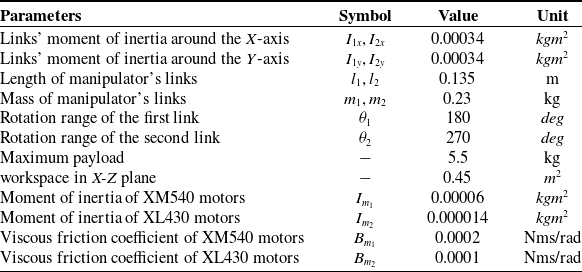
Figure 1 shows the robot structure. The WLM is a mobile robot with 10 degrees of freedom, comprising legs with attached wheels. The robot’s body is designed to accommodate additional equipment. To extend the robot’s workspace, a manipulator with two degrees of freedom, featuring two revolute joints, is mounted on the robot’s platform. The platform is designed and built to navigate diverse terrains and rough surfaces, enabling it to perceive its environment and transport objects. The maximum allowable payload for the manipulator is 5.5 kg. The manipulator’s workspace for the end-effector in the X-Z plane is 0.45 m2. Each link is 13.5 cm long and weighs 0.23 kg. The permissible rotation angle for the first link ranges from 0° to 180°, while for the second link, it ranges from −45° to 225°.
Schematic of the WLM parts.

The mechatronic parts include ten 150-watt Dynamixel motors. These consist of the hip joints, four XM540-W150-R servo motors with RS485 communication protocol, four XL430-W250-T motors with TTL communication protocol for the wheels, and two motors for the manipulator’s links. To determine the WLM’s posture, body position, and manipulator end-effector position, the robot uses MPU-6050 sensors for the main body and end-effector. This sensor is a 6-axis IMU combining an accelerometer and gyroscope. A relay module along with an SMPS2 Dynamixel power supply module is used to switch the robot’s power circuit on and off, which is connected to a 12V power supply that powers the robot’s motors. A buck converter module is employed to generate a stable DC current. The U2D2 board is a converter that establishes communication between the PC and the servo motors, enabling motor commands to be sent and feedback to be received. An interface board is provided to connect the motors to the U2D2 converter using the communication protocols. An Arduino Nano board with the I2C communication protocol is utilized to receive data from the MPU-6050 module and transmit it to the PC.
Actual specifications of manipulator and motors.

Table I shows the actual parameters of the manipulator. To maintain the robot’s stability and balance and to prevent it from tipping over, the manipulator is allowed to move only in the X-Z plane. Also, an arm with lightweight links and motors with suitable power has been used for applications in the WLM.
2.2. Robot slippage
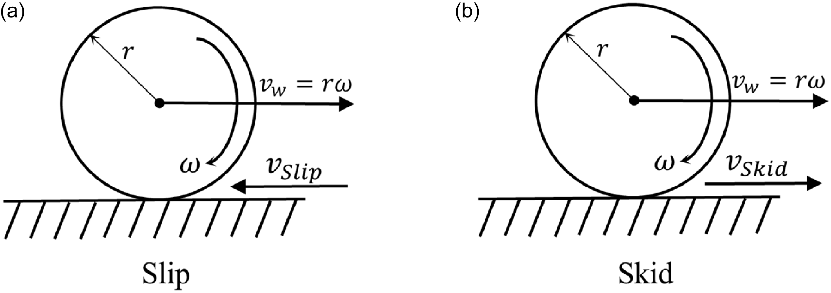
As illustrated in Figure 2, the deviation of the WLM from its planned trajectory is mainly caused by two factors. The first is a low slip coefficient at the wheel-ground interface, which leads to skidding. The second is rapid acceleration, wheel spinning, or sudden stops, which result in slipping. Both effects reduce traction at the contact points, causing energy loss and deviation from the intended path. Since the slip and skid vectors act in opposite directions and are difficult to separate, they are measured together as wheel slip and incorporated into the dynamic equations. Furthermore, longitudinal slip and unequal motion of the front wheels induce body rotation, leading to lateral slip and additional path deviation.
(a) Wheel slipping opposing the WLM’s motion, (b) Wheel skidding in the same direction as the WLM’s motion.

Each robot wheel’s slippage is obtained as follows [Reference Ding, Gao, Deng, Guo and Liu17]:
 \begin{equation} \boldsymbol{s}_{\boldsymbol{p}}=\frac{\boldsymbol{r}\boldsymbol{\omega} -\boldsymbol{v}_{\boldsymbol{w}}}{\boldsymbol{r}\boldsymbol{\omega} }\left(\boldsymbol{r}\boldsymbol{\omega} \geq \boldsymbol{v}_{\boldsymbol{w}},0\leq \boldsymbol{s}_{\boldsymbol{p}}\leq 1\right) \end{equation}
Where
 $\boldsymbol{r}$
is the wheel radius,
 $\boldsymbol{\omega}$
represents its angular velocity, and
 $\boldsymbol{v}_{\boldsymbol{w}}$
is the WLM’s wheel forward linear velocity. The skidding rate of each wheel is obtained as follows [Reference Ding, Gao, Deng, Guo and Liu17]:
 \begin{equation} \boldsymbol{s}_{\boldsymbol{d}}=\frac{\boldsymbol{v}_{\boldsymbol{w}}-\boldsymbol{r}\boldsymbol{\omega} }{\boldsymbol{v}_{\boldsymbol{w}}}\left(\boldsymbol{r}\boldsymbol{\omega} \leq \boldsymbol{v}_{\boldsymbol{w}},0\leq \boldsymbol{s}_{\boldsymbol{d}}\leq 1\right) \end{equation}
It can be concluded that the direction of the slipping rate and the skidding rate is opposite to each other. Therefore, the combined effects of these two factors are referred to as wheel slip:
 \begin{equation} \boldsymbol{s}_{\boldsymbol{p}}=-\boldsymbol{s}_{\boldsymbol{d}}=\frac{\boldsymbol{r}\boldsymbol{\omega} -\boldsymbol{v}_{\boldsymbol{w}}}{\boldsymbol{v}_{\boldsymbol{w}}}\left(\boldsymbol{r}\boldsymbol{\omega} \leq \boldsymbol{v}_{\boldsymbol{w}},-1\leq \boldsymbol{s}_{\boldsymbol{p}}\leq 0\right) \end{equation}
Wheel slip can be obtained from the deviation of the WLM’s actual movement and the WLM’s ideal motion:
 \begin{equation} \boldsymbol{s}_{\boldsymbol{l}}=\sum _{i=1}^{n}(| \boldsymbol{r}\boldsymbol{\omega} _{\boldsymbol{i}}-{\boldsymbol{v}_{\boldsymbol{w}}}_{\boldsymbol{i}}| {\unicode[Arial]{x0394}} t) \end{equation}
Where
 $n$
is the number of measurements and
 ${\unicode[Arial]{x0394}} t$
is the sampling time. Also, the lateral slip
 $\boldsymbol{v}_{\boldsymbol{y}}$
is obtained using the slip angle
 $\hat{\beta }$
from Eq. (5):
 \begin{equation} \boldsymbol{v}_{\boldsymbol{y}}=\boldsymbol{v}_{\boldsymbol{x}}\tan(\hat{\beta }) \end{equation}
In the above equation, the slip angle represents the angle between the robot’s velocity
 $\boldsymbol{v}_{\boldsymbol{x}}$
and its orientation. In measuring lateral slip
 $\boldsymbol{s}_{\boldsymbol{s}}$
, the amount of deviation from the ideal path at each moment is measured. On a straight path, the lateral velocity
 $\boldsymbol{v}_{\boldsymbol{d}}$
is equal to zero.
 \begin{equation} \boldsymbol{s}_{\boldsymbol{s}}=\sum _{i=1}^{n}(| \boldsymbol{v}_{\boldsymbol{d}}-\boldsymbol{v}_{\boldsymbol{y}}| {\unicode[Arial]{x0394}} t) \end{equation}
3. Development of the WLM’s model
In this section, the dynamic and kinematic modeling of the WLM under slip conditions is presented. A vector-based approach is used for the kinematics, while the Gibbs–Appell formulation is applied to derive the dynamics. The forces and torques of the manipulator’s actuators are obtained from the Gibbs functions and the system’s pseudo-accelerations. Slip effects are incorporated through a slip ratio, and frictional dynamics are approximated using a combined Coulomb model to reduce complexity.
The WLM’s modeling with leg wheel slippage is presented in this section. Figure 3 illustrates the WLM’s schematic along with its parameters and coordinate frames. The vector
 $\boldsymbol{r}_{\boldsymbol{o}}$
represents the platform’s position with relation to the earth reference frame,
 $\boldsymbol{r}_{\boldsymbol{EG}}$
is the directional vector from the gripper to the body’s center, and
 $\boldsymbol{r}_{\boldsymbol{FG}}$
is the directional vector from the first link’s end to the robot’s center of mass.
 $\theta _{1}$
is the first link angle of rotation, and
 $\theta _{2}$
is the second link angle of rotation. Point E indicates the manipulator’s end-effector, and F represents the joint of the manipulator’s second link. The vectors
 $\boldsymbol{r}_{\boldsymbol{lf}}$
,
 $\boldsymbol{r}_{\boldsymbol{rf}}$
,
 $\boldsymbol{r}_{\boldsymbol{lr}}$
, and
 $\boldsymbol{r}_{\boldsymbol{rr}}$
define the wheels’ center positions respective to the body’s center. α and β are the angular positions of the robot’s front legs and rear legs. Also, G is the WLM’s center of mass. Also,
 $\theta _{lf}$
,
 $\theta _{rf}$
,
 $\theta _{lr}$
, and
 $\theta _{rr}$
are the wheel rotation angles. The robot body dimensions are given by
 $l_{x}$
and
 $l_{y}$
for length and width, respectively. Point O denotes the wheel centers, while
 $\Psi$
and
 $\theta$
represent the robot body’s rotation angles around the Y-axis and Z-axis. Longitudinal slippage is indicated by
 $x_{slf}$
,
 $x_{srf}$
,
 $x_{slr}$
, and
 $x_{srr}$
, whereas
 $y_{slf}$
,
 $y_{srf}$
,
 $y_{slr}$
, and
 $y_{srr}$
denote lateral slippage of the wheels. The coordinate system of the robot is defined in the motivation plane, coinciding with its center of mass.
Schematic view of the WLM [Reference Asadi, Nikseresht and Korayem2].

3.1. Kinematics of the WLM
By representing the vectors of the links’ position and differentiating them, each respective link’s endpoint velocities, in relation to the WLM’s center of mass, are calculated. This process then allows us to derive the velocities of the WLM.
 \begin{equation} \boldsymbol{v}=\boldsymbol{v}_{\boldsymbol{G}}+\left(\dot{\Psi }\hat{\boldsymbol{j}}+\dot{\theta }\hat{\boldsymbol{k}}\right)\times \boldsymbol{r}_{\frac{\boldsymbol{link}}{\boldsymbol{G}}}+\dot{\boldsymbol{r}}_{\frac{\boldsymbol{link}}{\boldsymbol{G}}} \end{equation}
Here,
 $\boldsymbol{v}_{\boldsymbol{G}}$
is the body’s velocity including the effect of wheel slip terms, while
 $\boldsymbol{r}_{\frac{\boldsymbol{link}}{\boldsymbol{G}}}$
denotes the link’s endpoint vector to the structure’s center of mass. Additionally,
 $\dot{\boldsymbol{r}}_{\frac{\boldsymbol{link}}{\boldsymbol{G}}}$
indicates the relative velocity of the link’s endpoint concerning the platform. Due to the base of the manipulator undergoing rotational motion around the Z and Y axes of the body, the velocity’s second term significantly influences the overall velocity dynamics.
Next, the velocity of the body is expressed along the respective coordinate axes as follows [Reference Korayem, Nikseresht and Asadi3]:
 \begin{equation} (\boldsymbol{v}_{\boldsymbol{G}})_{x}=\dot{x},(\boldsymbol{v}_{\boldsymbol{G}})_{y}=\dot{y},(\boldsymbol{v}_{\boldsymbol{G}})_{z}=\dot{z}\end{equation}
In the given equation,
 $\dot{x}$
represents the body’s linear longitudinal velocity,
 $\dot{y}$
denotes the linear lateral velocity, and
 $\dot{z}$
corresponds to the linear vertical velocity. Then we write the manipulator’s links position vector.
The manipulator’s first link position vector:
 \begin{equation} \boldsymbol{r}_{\boldsymbol{FG}}=(l_{1}\cos (\theta _{1}+\Psi ))\hat{\boldsymbol{i}}+(l_{1}\sin (\theta _{1}+\Psi ))\hat{\boldsymbol{k}} \end{equation}
The manipulator’s second link position vector [Reference Asadi, Nikseresht and Korayem2]:
 \begin{equation} \boldsymbol{r}_{\boldsymbol{EG}}=(l_{1}\cos (\theta _{1}+\Psi )+l_{2}\cos (\theta _{1}+\theta _{2}+\Psi ))\hat{i}+(l_{1}\sin (\theta _{1}+\Psi )+l_{2}\sin (\theta _{1}+\theta _{2}+\Psi ))\hat{\boldsymbol{k}} \end{equation}
In the given equations,
 $l_{1}$
and
 $l_{2}$
represent the manipulator’s first and second link lengths, in that order.
 $\theta _{1}$
is the first link angle of rotation, and
 $\theta _{2}$
is the second link angle of rotation. Also, the position of each manipulator’s link can be determined using position vectors and the platform’s position.
The manipulator’s first link position:
 \begin{equation} x_{F}=(x+l_{1}\cos (\theta _{1}+\Psi ))\hat{\boldsymbol{i}}+(y)\hat{\boldsymbol{j}}+(z+l_{1}\sin (\theta _{1}+\Psi ))\hat{\boldsymbol{k}} \end{equation}
The manipulator’s second link position:
 \begin{equation}x_{E}=(x+l_{1}\cos (\theta _{1}+\Psi )+l_{2}\cos (\theta _{1}+\theta _{2}+\Psi ))\hat{\boldsymbol{i}}+(y)\hat{\boldsymbol{j}}+(z+l_{1}\sin (\theta _{1}+\Psi )+l_{2}\sin (\theta _{1}+\theta _{2}+\Psi ))\hat{\boldsymbol{k}}\end{equation}
In the given equations,
 $x$
represents the body’s linear longitudinal position,
 $x$
denotes the linear lateral position, and
 $z$
corresponds to the linear vertical position. By deriving from Eqs. (9) and (10), we can define the velocity vectors of each link of the manipulators concerning the platform.
The velocity vector of the manipulator’s first link:
 \begin{equation} \dot{\boldsymbol{r}}_{\boldsymbol{FG}}=({-}l_{1}(\dot{\theta }_{1}+\dot{\Psi })\sin (\theta _{1}+\Psi ))\hat{\boldsymbol{i}}+(l_{1}(\dot{\theta }_{1}+\dot{\Psi })\cos (\theta _{1}+\Psi ))\hat{\boldsymbol{k}} \end{equation}
The velocity vector of the manipulator’s second link:
 \begin{eqnarray}\dot{\boldsymbol{r}}_{\boldsymbol{EG}}&=&({-}l_{1}(\dot{\theta }_{1}+\dot{\Psi })\sin (\theta _{1}+\Psi )-l_{2}(\dot{\theta }_{1}+\dot{\theta }_{2}+\dot{\Psi })\sin (\theta _{1}+\theta _{2}+\Psi ))\hat{\boldsymbol{i}}+(l_{1}(\dot{\theta }_{1}+\dot{\Psi })\cos (\theta _{1}+\Psi )\nonumber\\&& +\ l_{2}(\dot{\theta }_{1}+\dot{\theta }_{2}+\dot{\Psi })\cos (\theta _{1}+\theta _{2}+\Psi ))\hat{\boldsymbol{k}}\end{eqnarray}
By writing Eq. (7) for each link of the manipulator, the manipulator’s links’ velocities are defined as follows.
The first link’s velocity:
 \begin{eqnarray}\boldsymbol{v}_{\boldsymbol{F}} &=& \left( {\dot x + {l_1}\dot \Psi \sin \left( {{\theta _1} + \Psi } \right) - {l_1}({{\dot \theta }_1} + \dot \Psi } \right)\sin \left( {{\theta _1} + \Psi } \right))\hat {\boldsymbol{i}} + \left( {{l_1}\dot \theta \cos \left( {{\theta _1} + \Psi } \right) + \dot y} \right)\hat {\boldsymbol{j}}\nonumber\\[5pt]&& + \left( {\dot z - {l_1}\dot \Psi \dot \theta \cos \left( {{\theta _1} + \Psi } \right) + {l_1}({{\dot \theta }_1} + \dot \Psi )\cos \left( {{\theta _1} + \Psi } \right)} \right)\hat {\boldsymbol{k}}\end{eqnarray}
The second link’s velocity:
 \begin{eqnarray}\boldsymbol{v}_{\boldsymbol{E}}&=&(\dot{x}+\dot{\Psi}(l_1 \sin (\theta_1+\Psi)+l_2 \sin (\theta_1+\theta_2+\Psi))-l_1 (\dot{\theta}_1+ \dot{\Psi})\sin (\theta_1+\Psi)-l_2(\dot{\theta}+\dot{\theta}_2 + \dot{\Psi}) \sin\nonumber\\[5pt]&& (\theta_1+\ \theta_2+\Psi))\hat{\boldsymbol{i}}+(\dot{y}+\dot{\theta}(l_1 \cos(\theta_1+\Psi)+l_2 \cos(\theta_1+\theta_2+\Psi))\hat{\boldsymbol{j}}+(\dot{z}-\dot{\Psi}(l_1 \cos(\theta_1+\Psi)\nonumber\\[5pt]&&+\ l_2 \cos(\theta_1+\theta_2+\Psi)+l_1 (\dot{\theta}+\dot{\Psi})\cos(\theta_1+\Psi)+l_2 (\dot{\theta}+\dot{\theta}_2+\dot{\Psi})\cos(\theta_1+\theta_2+\Psi))\hat{\boldsymbol{k}},\end{eqnarray}
Next, we utilize the above relationships to derive the hierarchical dynamic equation of the WLM in slip conditions.
3.2. Dynamics of the WLM
In the following, to derive the hierarchical equations of the WLM’s dynamics, we use the Gibbs–Appell formulation. While the recursive Gibbs–Appell formulation is powerful and has been applied in our prior works [Reference Korayem, Shafei, Doosthoseini, Absalan and Kadkhodaei12, Reference Korayem and Shafei13], in this study, we intentionally used the non-recursive form. This choice was made to simplify the integration of manipulator and base dynamics within a single hierarchical framework. Also, the manipulator’s pseudo-coordinates,
 $\theta _{1}$
and
 $\theta _{2}$
, are incorporated into the mechanism’s primary pseudo-coordinates, enabling the system’s accelerations to be expressed in terms of these variables. A Gibbs function specific to the manipulator is added to the robot’s Gibbs functions, resulting in a hierarchical structure for deriving the WLM’s dynamic equations. By applying the Gibbs formulation to the manipulator’s pseudo-coordinates and differentiating them individually, the WLM’s dynamic equations are achieved. The system’s Gibbs functions are calculated independently for each of the two sections of the WLM.
The Gibbs function of the main body [Reference Korayem, Nikseresht and Asadi3]:
 \begin{eqnarray}S_{b}&=&\frac{I_{o}}{2}\left(\ddot{\theta }_{rf}^{2}+\ddot{\theta }_{lf}^{2}+\ddot{\theta }_{rr}^{2}+\ddot{\theta }_{lr}^{2}\right)+I_{ly}\left(\ddot{\alpha }^{2}+\ddot{\beta }^{2}\right)+I_{lx}\ddot{\theta }^{2}\left({\kern-1.5pt}\cos ^{2}\alpha +\cos ^{2}\beta \right)+\frac{m_{l}}{2}\left(a_{rf}^{2}+a_{lf}^{2}+a_{rr}^{2}+a_{lr}^{2}\right)\nonumber\\&&+\ \frac{1}{2}\left(I_{Gz}\ddot{\theta }^{2}+I_{Gy}\ddot{\Psi }^{2}+M_{G}\boldsymbol{a}_{\boldsymbol{G}}^{\textbf{2}}\right)\end{eqnarray}
In these equations,
 $I_{o}$
represents the moment of inertia of the wheel’s axis, while
 $I_{ly}$
and
 $I_{lx}$
represent the legs’ moments of inertia with respect to the Y-axis and X-axis, respectively. The parameter
 $m_{l}$
denotes the mass of the robot’s legs, and
 $a_{lf}$
,
 $a_{rf}$
,
 $a_{lr}$
, and
 $a_{rr}$
indicate the WLM’s legs accelerations. Additionally,
 $I_{Gy}$
and
 $I_{Gz}$
represent the body’s moments of inertia around the Y-axis and Z-axis, respectively, while
 $M_{G}$
signifies the total mass of the WLM’s body. Finally,
 $\boldsymbol{a}_{\boldsymbol{G}}$
denotes the WLM’s center of mass acceleration.
The Gibbs function of the links:
 \begin{equation} S_{l}=\frac{I_{1}}{2}\left(\ddot{\theta }_{1}+\ddot{\Psi }\right)^{2}+\frac{I_{2}}{2}\left(\ddot{\theta }_{1}+\ddot{\theta }_{2}+\ddot{\Psi }\right)^{2}+\frac{m_{1}}{2}\left(\boldsymbol{a}_{\boldsymbol{F}}\right)^{2}+\frac{m_{2}}{2}\left(\boldsymbol{a}_{\boldsymbol{E}}\right)^{2} \end{equation}
where
 $I_{1}$
and
 $I_{2}$
are the first and second manipulator’s links moment of inertia,
 $m_{1}$
and
 $m_{2}$
are the first and second manipulator’s links mass and
 $\boldsymbol{a}_{\boldsymbol{F}}$
and
 $\boldsymbol{a}_{\boldsymbol{E}}$
are the manipulator’s links accelerations.
The dynamic model of a servo motor is given by:
 \begin{equation}\sum\nolimits_{i=1}^{n}\ I_{m}\ \ddot{\theta}_{i}^{2} + \frac{1}{2}\sum\nolimits_{i=1}^{n}\ B_{m}\ \dot{\theta}_{i}^{2} = \tau_{m}\end{equation}
Where,
 $n$
is the number of motors,
 $I_{m}$
represents the motor’s moment of inertia,
 $\ddot{\theta }_{i}$
and
 $\dot{\theta }_{i}$
denote the angular acceleration and angular velocity of the motors, respectively,
 $B_{m}$
is the viscous friction coefficient, and
 $\tau _{m}$
is the torque produced by the motor. The second term of the Eq. (19) is expressed as a Rayleigh dissipation function so that it can be used in the Gibbs–Appell equations [Reference Korayem, Shafei, Doosthoseini, Absalan and Kadkhodaei12]. There are six XL430 motors and four XM540 motors, and Eq. (19) is split into two separate functions accordingly.
The Gibbs function of the motors:
 \begin{equation}S_{m}=I_{{m_{1}}}\left(\ddot{\alpha }^{2}+\ddot{\beta }^{2}\right)+\frac{I_{{m_{2}}}}{2}\left(\ddot{\theta }_{rf}^{2}+\ddot{\theta }_{lf}^{2}+\ddot{\theta }_{rr}^{2}+\ddot{\theta }_{lr}^{2}+\ddot{\theta }_{1}^{2}+\ddot{\theta }_{2}^{2}\right)\end{equation}
The viscous damping force of the motors is incorporated into the Rayleigh dissipation function as:
 \begin{equation}D_{m}=B_{{m_{1}}}\left(\dot{\alpha }^{2}+\dot{\beta }^{2}\right)+\frac{B_{{m_{2}}}}{2}\left({\dot{\theta }_{rf}}^{2}+{\dot{\theta }_{lf}}^{2}+{\dot{\theta }_{rr}}^{2}+{\dot{\theta }_{lr}}^{2}+{\dot{\theta }_{1}}^{2}+{\dot{\theta }_{2}}^{2}\right)\end{equation}
Then the WLM’s Gibbs function is gained by combining Eq. (17) with Eqs. (18) and (20):
 \begin{eqnarray}S_{\textit{total}}&=&\frac{I_{o}}{2}\left(\ddot{\theta }_{rf}^{2}+\ddot{\theta }_{lf}^{2}+\ddot{\theta }_{rr}^{2}+\ddot{\theta }_{lr}^{2}\right)+I_{ly}\left(\ddot{\alpha }^{2}+\ddot{\beta }^{2}\right)+I_{lx}\ddot{\theta }^{2}\left({\kern-1.5pt}\cos ^{2}\alpha +\cos ^{2}\beta \right)+\frac{m_{l}}{2}\left(a_{rf}^{2}+a_{lf}^{2}+a_{rr}^{2}+a_{lr}^{2}\right)\nonumber\\&&+\ \frac{1}{2}\left(I_{Gz}\ddot{\theta }^{2}+I_{Gy}\ddot{\Psi }^{2}+M_{G}\boldsymbol{a}_{\boldsymbol{G}}^{\textbf{2}}\right)+\frac{I_{1}}{2}\left(\ddot{\theta }_{1}+\ddot{\Psi }\right)^{2}+\frac{I_{2}}{2}\left(\ddot{\theta }_{1}+\ddot{\theta }_{2}+\ddot{\Psi }\right)^{2}+\frac{m_{1}}{2}\left(\boldsymbol{a}_{\boldsymbol{F}}\right)^{2}+\frac{m_{2}}{2}\left(\boldsymbol{a}_{\boldsymbol{E}}\right)^{2}\nonumber\\&& +\ I_{{m_{1}}}\left(\ddot{\alpha }^{2}+\ddot{\beta }^{2}\right)+\frac{I_{{m_{2}}}}{2}\left(\ddot{\theta }_{rf}^{2}+\ddot{\theta }_{lf}^{2}+\ddot{\theta }_{rr}^{2}+\ddot{\theta }_{lr}^{2}+\ddot{\theta }_{1}^{2}+\ddot{\theta }_{2}^{2}\right)\end{eqnarray}
Following this, the WLM robot body’s potential energy function is determined using the equation below [Reference Korayem, Nikseresht and Asadi3]:
 \begin{equation} V_{b}=gl\left(m_{l}\left({\kern-1.5pt}\sin \left(\alpha \right)+\sin \left(\beta \right)\right)+\frac{M_{G}}{2}\left({\kern-1.5pt}\sin \left(\alpha +\Psi \right)+\sin \left(\beta +\Psi \right)\right)\right) \end{equation}
Here,
 $g$
denotes gravitational acceleration. The potential function of the manipulator is determined using the following equation.
 \begin{eqnarray}V_{m}&=&g\left(m_{1}\left(\frac{1}{2}l_{1}\sin \left(\theta _{1}\right)+\frac{1}{2}l_{x}\sin \left(\Psi \right)+l\sin \left(\alpha \right)\right)\right.\nonumber\\&&+\left. m_{2}\left(l_{1}\sin \left(\theta _{1}\right)+\frac{1}{2}l_{2}\sin \left(\theta _{1}+\theta _{2}\right)+\frac{1}{2}l_{x}\sin \left(\Psi \right)+l\sin \left(\alpha \right)\right)\right)\end{eqnarray}
The function of potential energy of the WLM is then obtained by combining the function of the body and the manipulator’s potential energy. The function is achieved by integrating Eqs. (23) and (24) as shown below:
 \begin{eqnarray}V_{total}&=&gl\bigg(m_l ({\kern-1.5pt}\sin(\alpha)+\sin(\beta) )+\frac{M_G}{2}({\kern-1.5pt}\sin(\alpha+\Psi)+\sin(\beta+\Psi))\bigg)\nonumber\\&&+\ g(m_1 \bigg(\frac{1}{2} l_1 \sin(\theta_1 )+\frac{1}{2} l_x \sin(\Psi)+l\sin(\alpha) \bigg)\nonumber\\&&+\ m_2 \bigg(l_1 \sin(\theta_1 )+ \frac{1}{2} l_2 \sin(\theta_1+\theta_2 )+ \frac{1}{2} l_x \sin(\Psi)+l\sin(\alpha) \bigg)\end{eqnarray}
We define the friction function of the wheels considering the Coulomb friction as follows. This function considers the dynamic treatment of the wheels, legs, and manipulator, and it is essential in modeling the system’s motion due to friction [Reference Korayem, Nikseresht and Asadi3]:
 \begin{eqnarray}D_w&=& \mu_{dx} (F_{nf} (\dot{x}_{srf}\, sgn(\dot{x}_{srf} )+\dot{x}_{slf}\, sgn(\dot{x}_{slf} ) )+F_{nr} (\dot{x}_{srr}\, sgn(\dot{x}_{srr} )+\dot{x}_{slr}\, sgn(\dot{x}_{slr} ) )\nonumber\\&&+\ 2\mu_{dy} (F_{nf} \dot{y}_f\, sgn(\dot{y}_f )+F_{nr} \dot{y}_r\, sgn(\dot{y}_r ))\end{eqnarray}
In the above equation,
 $\mu _{dx}$
is the longitudinal coefficient and
 $\mu _{dy}$
is the lateral coefficient of the WLM’s wheels friction. Additionally,
 $F_{nf}$
is the front wheels’ normal forces and
 $F_{nr}$
is the rear wheels’ normal forces. By combining the Eqs. (21) and (26) the total dissipation function of the WLM can be obtained as follows:
 \begin{eqnarray}D_{total}&=& \mu_{dx} (F_{nf} (\dot{x}_{srf}\, sgn(\dot{x}_{srf} )+\dot{x}_{slf}\, sgn(\dot{x}_{slf} ) )+F_{nr} (\dot{x}_{srr}\, sgn(\dot{x}_{srr} )+\dot{x}_{slr}\, sgn(\dot{x}_{slr} ) )+2\mu_{dy} (F_{nf} \dot{y}_f\, sgn(\dot{y}_f )\nonumber\\&&+\ F_{nr} \dot{y}_r\, sgn(\dot{y}_r )) +B_(m_1 ) (\dot{\alpha}^2+ \dot{\beta}^2)+\frac{B_{m_2}}{2}\left(\dot{\theta}_{rf}^2+\dot{\theta}_{lf}^2+\dot{\theta}_{rr}^2+\dot{\theta}_{lr}^2+\dot{\theta}_1^2+\dot{\theta}_2^2\right) \end{eqnarray}
The Gibbs equation is stated as a system of equations that incorporates both the dynamic and kinematic behaviors of the mechanism under the influence of slip conditions. This formulation considers the forces and torques generated by wheel slippage, as well as the changes in the acceleration and velocity of the WLM’s components, including the wheels and manipulators, as they interact with the surrounding environment. By factoring in slip, the Gibbs equation offers a clearer depiction of the robot’s movement, enabling a thorough analysis of its performance across various surfaces and terrains [Reference Korayem, Nikseresht and Asadi3]:
 \begin{equation} \frac{\partial S_{\textit{total}}}{\partial \ddot{q}}+\frac{\partial D_{\textit{total}}}{\partial \dot{q}}+\frac{\partial V_{\textit{total}}}{\partial q}=\tau \end{equation}
Here,
 $q$
denotes the system’s pseudo-coordinates, and the generalized torques are represented by
 $\tau$
. The identification of 14 pseudo-coordinates as independent coordinates has been made, and we focus on the manipulator’s pseudo-coordinates,
 $\theta _{1}$
and
 $\theta _{2}$
. The formulation of the remaining 12 pseudo-coordinates can be found in our previous work [Reference Korayem, Nikseresht and Asadi3]. Finally, we derive the torque equations for the manipulator’s links:
Torque of first link’s motor:
 \begin{eqnarray}\tau _{\theta 1}&=& I_{1}\left(\ddot{\theta }_{1}+\ddot{\Psi }\right)+I_{2}\left(\ddot{\theta }_{1}+\ddot{\theta }_{2}+\ddot{\Psi }\right)+g\left(\frac{m_{1}l_{1}\cos \left(\theta _{1}\right)}{2}+m_{2}\left(l_{1}\cos \left(\theta _{1}\right)+\frac{l_{2}\cos \left(\theta _{1}+\theta _{2}\right)}{2}\right)\right)\nonumber\\&&+\ I_{{m_{2}}}\ddot{\theta }_{1}+B_{{m_{2}}}\dot{\theta }_{1}\end{eqnarray}
Torque of second link’s motor:
 \begin{equation}\tau _{\theta 2}=I_{2}\left(\ddot{\theta }_{1}+\ddot{\theta }_{2}+\ddot{\Psi }\right)+\frac{m_{2}l_{2}g\cos \left(\theta _{1}+\theta _{2}\right)}{2}+I_{{m_{2}}}\ddot{\theta }_{2}+B_{{m_{2}}}\dot{\theta }_{2}\end{equation}
4. Simulations and experimental results
The motion of the WLM mechanism is illustrated in Figure 4. The robot was modeled and simulated in Webots, which utilizes the Open Dynamics Engine (ODE) physics engine. Webots was chosen for its ease of modeling, seamless integration of sensors and actuators, high simulation accuracy, and fast computation of robot motion. Additionally, it provides estimates of slip ratios and other physical parameters, facilitating detailed analysis of robot-terrain interactions. The kinematic and dynamic equations, including the effects of wheel slip, were derived using MATLAB and Maple. To account for stochastic variations in slip, a constant slip coefficient was assumed in the simulations. The resulting simulation data were then systematically validated against experimental measurements, ensuring that the model accurately captures the robot’s real-world behavior.
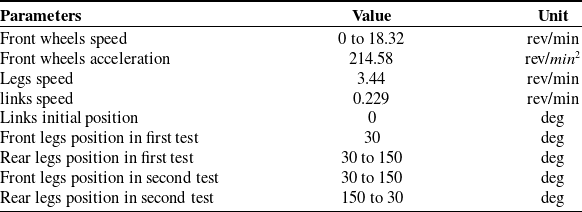
Inputs of WLM in experimental tests.

Illustration of the WLM in Webots, showing manipulator torque and normal forces on the wheels.

Table II the input parameters of the WLM during both experimental tests and simulations. To avoid over-actuation and ensure controlled motion, the rear wheels were left in a free-rolling state without any actuation, while only the front wheels were actively driven. Moreover, the leg joints and manipulator links were moved at constant velocity without acceleration, which helped maintain smooth, uniform motion of the robot and minimized transient dynamics that could affect the accuracy of trajectory tracking. This controlled input strategy allowed for a clear assessment of the robot’s response and the effects of wheel slip, actuator dynamics, and surface interactions.
Figure 5 shows the components used in the practical tests of the WLM. To study the influence of the robot body’s dynamics on the manipulator, two experiments were designed in which the manipulator performed the same motion while the body moved differently. In the first case, the front wheels were driven and accelerated while the rear wheels spun freely. In the second case, the front legs remained fixed, the rear leg angles were varied, and the WLM rotated along a circular path. A further scenario was tested in which both front and rear leg angles were varied simultaneously. To reduce the impact of wheel slip and skid, the robot’s components should be distributed evenly across the body or placed close to the center of mass. In addition, manipulator motion increases the overall influence of wheel slip on system performance.
Equipment used in experimental testing.

4.1. Slip measurement
To quantify the amount of slippage experienced by the robot, an IMU (MPU-6050) sensor mounted on the robot body was employed [Reference Korayem, Nikseresht and Asadi3]. The sensor provides an orientation accuracy of approximately ±0.5° and an acceleration accuracy of ±0.02 m/s2, which were considered when evaluating measurement uncertainty. Slip was estimated by comparing the actual displacement of the robot, obtained via IMU-based integration, with the ideal planned trajectory. Prior to experimentation, the MPU-6050 was calibrated to minimize bias and enhance measurement precision. Gyroscope calibration was performed by keeping the sensor stationary on a flat surface, recording the mean offsets of angular velocity along all three axes, and compensating for these offsets in subsequent measurements to reduce drift. Accelerometer calibration involved positioning the sensor in six known orientations, aligning each axis with gravity in both positive and negative directions, comparing the measured accelerations to the expected ±1 g, and calculating scale factors and biases for correction. This procedure reduced systematic errors and ensured reliable measurements of angular velocity and acceleration during testing. Despite calibration, uncertainty remained in slip estimation due to accelerometer noise (±30–50 mg), gyroscope noise (∼0.005 °/s/
 $\surd$
Hz), residual bias drift, sensor misalignment, and limited sampling rate. Variations in surface conditions (dry vs. wet ceramic) further increased measurement error. Overall, slip measurement uncertainty was estimated to be 5–10% of the computed slip ratio. Friction coefficients were derived experimentally from tests conducted on dry and wet (soapy) ceramic surfaces. By integrating IMU-derived acceleration and orientation data, the actual displacement of the robot body was estimated for each time step, and slippage was computed by comparing this displacement with the ideal trajectory. The longitudinal friction coefficient (
 $\mu _{dx}$
) between the robot’s rubber wheels and the ceramic tile was measured as 1.2 on dry, dusty ceramic and 0.65 on wet, soapy ceramic, based on experimental observations of wheel speed and contact conditions [Reference Nikolić, Banić, Stamenković, Simonović, Miltenović and Pavlović31]. The ratio of longitudinal to lateral friction coefficients (
 $\mu _{dx}$
/
 $\mu _{dy}$
) was assumed to be approximately 1.1 [Reference Xia, Liu and Lu32], resulting in lateral coefficients (
 $\mu _{dy}$
) of 1.09 and 0.59 for dry and wet surfaces, respectively. Wheel slip and skid were modeled using a combination of Coulomb and viscous friction laws, with longitudinal and lateral slip coefficients defined from empirical data and assumed constant in simulations, consistent with prior studies [Reference Nikolić, Banić, Stamenković, Simonović, Miltenović and Pavlović31, Reference Xia, Liu and Lu32]. The Dynamixel XM540-W150-R and XL430-W250-T actuators introduce additional uncertainty due to mechanical tolerances, sensor inaccuracies, communication latency, and environmental factors. Position accuracy is typically within ±0.1° –0.2°, while torque output may fluctuate by ±5%. Communication delay is approximately 1–2 ms. These errors can be mitigated through periodic calibration, maintaining a stable power supply, optimizing communication parameters, and controlling operating conditions such as temperature and electromagnetic interference, thereby improving overall motor reliability during robotic experiments.
4.2. WLM’s first test
The robot’s first test on dry, dusty ceramic demonstrates that the WLM accelerates, rotating its rear legs from 30° to 150°, while the front legs remain fixed at 30° (Figure 6). The WLM’s links begin moving from a 0° angle at the front of the platform without acceleration. The front wheels rotate with acceleration, whereas the rear wheels remain stationary. Overall, the legs exhibit uniform motion, with no additional acceleration.
Robot and manipulator movement in the first test.

WLM’s end-effector position during the first test of the robot.

The robot body’s displacement strongly influences the WLM’s end-effector trajectory during the first test, reflecting both the body’s motion and the arm’s own movement (Figure 7). The results also indicate that wheel slip has minimal effect on changes in the end-effector’s height along the z-axis.
Wheel slip causes minor differences between the experimental and simulation speed profiles of the WLM’s end-effector during the first test, although their overall behavior remains similar (Figure 8).
Velocity of end-effector during the first test.

The manipulator’s end-effector movement is coupled with the robot body’s motion during the first test, resulting in a combined trajectory as the robot moves through space (Figure 9).
3D position of WLM in the first test.

Figures 7–9 show the manipulator’s end-effector position and velocity during the first test. While the overall trends in simulation and experiment agree, deviations of 8–12% were observed due to wheel slip. Slip had minimal effect on the end-effector’s vertical motion but significantly influenced its horizontal trajectory. Figure 10 presents the arm joint torques. The first joint requires more torque than the second, as it must support the torque of the second link.
Torque of WLM joints in the first test.

4.3. WLM’s second test
During the second test on wet, soapy ceramic with uneven terrain, the rear legs rotate from 150° to 30° while the front legs move from 30° to 150°. The WLM’s links at the front start from 0° without acceleration, with the front wheels rotating under acceleration and the rear wheels remaining stationary. The legs move at a constant velocity, and the WLM follows a circular path, with the left front wheel speed approaching zero (Figure 11).
Robot and manipulator circular movement on wet and soapy ceramic in the second test.

Wheel slip and skid during accelerated motion cause some deviation along the x-axis in the WLM’s end-effector position during the second test, although the overall behavior remains similar (Figure 12).
WLM’s end-effector position during the second test of the robot.

Figure 13 shows the WLM’s end-effector velocity during the second test. The robot body’s speed and acceleration strongly influence the arm’s velocity profile, causing the end-effector to follow both its own motion and the body’s movement.
Velocity of end-effector in the second test.

Figure 14 illustrates the WLM’s three-dimensional position during the second test. It shows the end-effector’s motion relative to the robot body, demonstrating that the end-effector undergoes a combined movement as the robot moves through space.
3D Circular position of WLM in the second test.

In this test (Figures 12–14), the WLM followed a circular path. End-effector deviations of 10–14% between simulation and experiment were observed, primarily due to increased slip and skid during accelerated motion. Experimental velocity profiles confirmed the strong coupling between the manipulator and the platform’s body dynamics. Figure 15 shows the arm joint torques during the second test. The torques are similar to those in the first test, despite different body motion, indicating that the manipulator’s dynamics are largely independent of the robot body’s movement.
4.4. Systematic error analysis
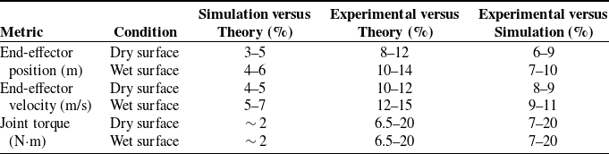
To further validate the Gibbs–Appell–based hierarchical model, a quantitative comparison was performed among the theoretical predictions, Webots simulation results, and experimental measurements. The evaluation focused on the end-effector position, velocity, and manipulator joint torque under both dry and wet (soapy ceramic) surface conditions. Error metrics were computed as mean percentage differences between the root mean square (RMS) magnitudes of corresponding data over one complete motion cycle of the robot.
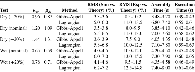
A comprehensive analysis was conducted to identify and quantify the sources of deviation between theoretical models, simulations, and experimental results of the robot in Table III. Overall, the theoretical and Webots simulation results showed close agreement, while larger deviations appeared in physical experiments – particularly on wet or low-traction surfaces. Torque analysis revealed that the first joint consistently required higher torque than the second due to load transmission, with initial deviations of approximately 6.5% and 20%, respectively, converging after 8–14 s. End-effector position errors in experiments ranged between 8 and 12%, primarily attributed to wheel slip, frictional variability, and sensor uncertainty. Slip ratios of 5–10% were observed on dry (
 $\mu _{dx}$
≈ 1.2) and wet or soapy (
 $\mu _{dx}$
≈ 0.65) surfaces, leading to trajectory deviations of about 8–10.5%. Additional discrepancies stemmed from actuator nonidealities – such as torque ripple, backlash, saturation, and communication delay – as well as unmodeled compliance and elastic deformation in legs and wheels, which introduced phase shifts in torque and velocity. Sensor limitations, including IMU drift (e.g., MPU-6050), ±0.02 m/s2 noise, and encoder quantization, contributed roughly 5–10% uncertainty in position estimation. Model simplifications, including assumptions of rigid links, constant friction coefficients, linear damping, and neglect of tire deformation and thermal effects, accounted for residual errors of 3–5%. Collectively, these factors explain most of the observed discrepancies between simulation and experiment. Future improvements should focus on closed-loop compensation, online slip and friction estimation, compliance modeling, and incorporation of additional feedback sources such as wheel encoders and visual odometry to enhance model fidelity and robustness.
4.5. Gibbs–Appell vs. Lagrangian formulations
To quantitatively validate the performance of the proposed Gibbs–Appell formulation, a comparative study was conducted against an equivalent Lagrangian-based model using the same setup and data from the two experimental tests presented in this paper. Test 1 involved linear motion on a dry ceramic surface, while Test 2 examined a circular trajectory on a wet ceramic surface coated with a water and soap mixture. In both tests, the models were evaluated using identical input trajectories, link parameters, and friction coefficients as reported in the manuscript. The comparison metrics included the root-mean-square (RMS) error between theoretical predictions, simulation results, and experimental measurements, as well as the symbolic assembly and numerical execution times. For the dry surface, the friction coefficients were set as
 $\mu _{dx}$
= 1.20 and
 $\mu _{dy}$
= 1.09, while for the wet surface, they were defined as
 $\mu _{dx}$
= 0.65 and
 $\mu _{dy}$
= 0.59. To evaluate the sensitivity of both formulations, a ±20% variation was applied to
 $\mu _{dx}$
, with
 $\mu _{dx}$
/
 $\mu _{dy}=1.1$
.
Comparison of average absolute errors.

Torque of WLM joints in the second test.

Quantitative comparison between the Gibbs–Appell and Lagrangian formulations.

Table IV summarizes the quantitative comparison between the Gibbs–Appell and Lagrangian formulations under varying friction coefficients for both physical tests of the WLM. The Gibbs–Appell formulation consistently achieves lower RMS errors in simulations and experiments. For Test 1 (dry), end-effector RMS errors are 3–4% (simulation) and 8–10% (experimental), while for Test 2 (wet) they are 4–5% and 10–12%, respectively. The symbolic assembly time for Gibbs–Appell ranges from 3.48 to 4.58 s and execution time from 0.39 to 0.49 s, both markedly lower than the Lagrangian model (6.8–8.0 s and 0.55–0.66 s). When μ_dx varies by ±20%, Gibbs–Appell accuracy changes less than ±5%, while the Lagrangian model deviates up to ±15%, demonstrating the superior robustness of Gibbs–Appell dynamics to friction uncertainty. Comparative and sensitivity analyses confirm its higher accuracy and computational efficiency. Symbolic assembly is nearly twice as fast, and prediction accuracy improves, validating earlier qualitative findings. Symbolic differentiation and numerical evaluation were executed in MATLAB software; timing was measured using MATLAB’s tic–toc.
The hierarchical Gibbs–Appell framework provides accurate dynamic prediction and supports various control and planning tasks. By decoupling platform and manipulator dynamics, it enables efficient inverse dynamics computation and real-time feedforward control. Model-based slip estimation enhances adaptive gain tuning and online compensation, improving robustness under changing contact conditions. Its computational efficiency supports real-time trajectory optimization with slip and contact constraints, enabling rapid re-planning in uncertain environments. The hierarchical structure also facilitates residual generation for fault diagnosis, including slip detection, actuator degradation, and sensor faults.
5. Conclusion
This study presented the dynamic and kinematic modeling of a wheeled-legged manipulator (WLM) under slip conditions using the Gibbs–Appell formulation. By explicitly incorporating wheel skidding and slipping into the hierarchical equations of motion, the model better reflects real-world uncertainties compared to simplified slip-free assumptions. The kinematic and dynamic behavior of the WLM was modeled and simulated. The robot was implemented in the Webots simulation environment, and identical inputs were applied in both Webots and MATLAB simulations to validate the model. The results showed strong agreement between theoretical predictions, simulations, and experimental data. Two test scenarios were performed: straight-line and circular motion on flat terrain with different leg configurations, wheel speeds, and acceleration conditions. In both cases, experimental results were compared with theoretical predictions. The assumption of slip-free motion was shown to be unrealistic, especially on low-friction surfaces. When a slip occurred, the robot’s behavior deviated noticeably from the ideal model. This confirms the importance of explicitly modeling friction forces and slip at the wheel-ground interface. A key finding was that the body dynamics are influenced by the manipulator, whereas the manipulator dynamics are largely independent of the body. Similarly, manipulator kinematics depend on the body’s kinematics, but not vice versa. Using a hierarchical Gibbs–Appell formulation, the manipulator and body were modeled as two subsystems whose equations can be derived independently and then combined. The motor torques of the manipulator’s joints were determined through pseudo-acceleration equations and Gibbs functions. Experimental results showed that wheel slip caused positional errors of 8–12% in the first test and 10–14% in the second test. Torque differences between simulation and experiment were initially 6.5% for the first joint and 20% for the second joint, but these discrepancies decreased over time, converging after about 8 and 14 s, respectively. Overall, this research improves accuracy by removing simplifying assumptions, such as slip-free motion, and by formulating hierarchical system equations. The influence of motor dynamics was found to be negligible due to the characteristics of the Dynamixel motors. In future work, we plan to extend this framework by designing and implementing closed-loop path-tracking controllers to enhance robustness against slip and external disturbances. Additionally, real-time estimation of slip coefficients will be investigated to further improve model accuracy. The Gibbs–Appell formulation demonstrates superior accuracy, faster computation, and greater robustness to friction variations compared to the Lagrangian model across both dry and wet WLM tests. Collectively, the capabilities of the hierarchical Gibbs–Appell formulation demonstrate that the proposed modeling framework is not only analytically efficient but also highly applicable to control, trajectory planning, and system monitoring in real-world wheel–legged mobile (WLM) platforms. Its structured dynamic representation allows seamless integration into real-time controllers and optimization algorithms, ensuring accurate motion prediction and robust performance under varying terrain and contact conditions.
Author contributions
Korayem and Nikseresht conceived and designed the study. Nikseresht conducted data gathering. Nikseresht performed simulation analyses. Nikseresht and Al-Maliki wrote the article.
Financial support
This research received no specific grant from any funding agency, commercial or not-for-profit sectors.
Competing interests
The authors declare no conflicts of interest exist.
Ethical approval
Not applicable.
Appendix A: Additional kinematic equations
By deriving from Eqs. (15) and (16), we can define the acceleration of each link of the manipulators.
Acceleration of the manipulator’s first link:
 \begin{eqnarray}\boldsymbol{a}_{\boldsymbol{F}} &=& \big( \ddot{x} + l_1 \ddot{\Psi} \sin(\theta_1 + \Psi) + l_1 \dot{\Psi} (\dot{\theta}_1 + \dot{\Psi}) \cos(\theta_1 + \Psi)\nonumber\\&& - \ l_1 (\ddot{\theta}_1 + \ddot{\Psi}) \sin(\theta_1 + \Psi) - l_1 (\dot{\theta}_1 + \dot{\Psi})^2 \cos(\theta_1 + \Psi) \big) \hat{\boldsymbol{i}}\nonumber\\ && +\ \big( \ddot{y} + l_1 \dot{\theta}_1 \cos(\theta_1 + \Psi) - l_1 \dot{\theta}_1 (\dot{\theta}_1 + \dot{\Psi}) \sin(\theta_1 + \Psi) \big) \hat{\boldsymbol{j}}\nonumber\\ && +\ \big( \ddot{z} - l_1 \ddot{\Psi} \cos(\theta_1 + \Psi) + l_1 \dot{\Psi} (\dot{\theta}_1 + \dot{\Psi}) \sin(\theta_1 + \Psi) + l_1 (\dot{\theta}_1 + \dot{\Psi})^2 \sin(\theta_1 + \Psi) \big) \hat{\boldsymbol{k}}\end{eqnarray}
Acceleration of the manipulator’s second link:

Appendix B: Additional dynamic equations
The WLM’s center of mass acceleration is given by:
 \begin{eqnarray}\boldsymbol{a}_{\boldsymbol{G}}&=&\bigg(\frac{1}{2}(l((\ddot{\alpha }+\ddot{\Psi })\sin (\alpha +\Psi )+(\dot{\alpha }+\dot{\Psi })^{2}\cos (\alpha +\Psi )+(\ddot{\beta }+\ddot{\Psi })\sin (\beta +\Psi )\nonumber\\&&+\ (\dot{\beta }+ \dot{\Psi })^{2}\cos (\beta +\Psi )))+\frac{\ddot{x}_{srf}+\ddot{x}_{slf}+\ddot{x}_{srr}+\ddot{x}_{slr}+a(\ddot{\theta }_{rf}+\ddot{\theta }_{lf}+\ddot{\theta }_{rr}+\ddot{\theta }_{lr})}{4}\bigg)\hat{\boldsymbol{i}}\nonumber\\&&+\ \bigg({-}\frac{1}{4l_{y}}(l(\ddot{x}_{srf}+\ddot{x}_{srr}-\ddot{x}_{slf}-\ddot{x}_{slr}+a(\ddot{\theta }_{rf}+\ddot{\theta }_{rr}-\ddot{\theta }_{lf}-\ddot{\theta }_{lr}))({\kern-1.5pt}\cos (\alpha +\Psi )+\cos (\beta +\Psi )))\nonumber\\&&-\ \frac{1}{4l_{y}}(l(\dot{x}_{srf}+\dot{x}_{srr}-\dot{x}_{slf}-\dot{x}_{slr}+a(\dot{\theta }_{rf}+\dot{\theta }_{rr}-\dot{\theta }_{lf}-\dot{\theta }_{lr}))({-}(\dot{\alpha }+\dot{\Psi })\sin (\alpha +\Psi )\nonumber\\&&-\ (\dot{\beta }+\dot{\Psi })\sin (\beta +\Psi )))+\frac{\ddot{y}_{f}+\ddot{y}_{r}}{2}\bigg)\hat{\boldsymbol{j}}+\bigg({-}\frac{1}{2}(l((\ddot{\alpha }+\ddot{\Psi })\cos (\alpha +\Psi )-(\dot{\alpha }+\dot{\Psi })^{2}\sin (\alpha +\Psi )\nonumber\\&&+\ (\ddot{\beta }+\ddot{\Psi })\cos (\beta +\Psi )-(\dot{\beta }+\dot{\Psi })^{2}\sin (\beta +\Psi )))+\frac{1}{2l_{y}}\bigg(\frac{1}{2}(l((\dot{\alpha }+\dot{\Psi })\sin (\alpha +\Psi )\nonumber\\&&+\ (\dot{\beta }+\dot{\Psi })\sin (\beta +\Psi )))+\frac{\dot{x}_{srf}+\dot{x}_{slf}+\dot{x}_{srr}+\dot{x}_{slr}+a(\dot{\theta }_{rf}+\dot{\theta }_{lf}+\dot{\theta }_{rr}+\dot{\theta }_{lr})}{4}(\dot{x}_{srf}+\dot{x}_{srr}\nonumber\\&&-\ \dot{x}_{slf}-\dot{x}_{slr}+a(\dot{\theta }_{rf}+\dot{\theta }_{rr}-\dot{\theta }_{lf}-\dot{\theta }_{lr}))\bigg)\bigg)\hat{\boldsymbol{k}}\end{eqnarray}
In this context,
 $\ddot{x}$
,
 $\ddot{y}$
,
 $\ddot{z}$
are the acceleration components of the body in each corresponding axis direction. The following equation is used to determine the wheels’ normal forces. The normal force of the front wheel:
 \begin{eqnarray}F_{nf}&=&\frac{1}{l_{x}\cos \left(\Psi \right)+l\left({\kern-1.5pt}\cos \left(\alpha +\Psi \right)-\cos \left(\beta +\Psi \right)\right)}\left(\frac{1}{2}M_{G}g\left(\frac{1}{2}l_{x}\cos \left(\Psi \right)-l\cos \left(\beta +\Psi \right)\right)\right.\nonumber\\&&+\left. m_{l}g\left(l_{x}\cos \left(\Psi \right)+\frac{1}{2}l\cos \left(\alpha +\Psi \right)-\frac{3}{2}l\cos \left(\beta +\Psi \right)\right)\right)\nonumber\\&&+\ m_{1}g\left(\frac{1}{2}l_{x}\cos \left(\Psi \right)-l\cos \left(\beta +\Psi \right)+\frac{1}{2}l_{1}\cos \left(\theta _{1}+\Psi \right)\right)\nonumber\\&&+\ m_{2}g\left(\frac{1}{2}l_{x}\cos \left(\Psi \right)-l\cos \left(\beta +\Psi \right)+l_{1}\cos \left(\theta _{1}+\Psi \right)+\frac{1}{2}l_{2}\cos \left(\theta _{1}+\theta _{2}+\Psi \right)\right)\end{eqnarray}
The normal force of the rear wheel:
 \begin{eqnarray}F_{nr}&=&\frac{1}{l_{x}\cos \left(\Psi \right)+l\left({\kern-1.5pt}\cos \left(\alpha +\Psi \right)-\cos \left(\beta +\Psi \right)\right)}\left(\frac{1}{2}M_{G}g\left(\frac{1}{2}l_{x}\cos \left(\Psi \right)+l\cos \left(\alpha +\Psi \right)\right)\right.\nonumber\\&&+\left. m_{l}g\left(l_{x}\cos \left(\Psi \right)+\frac{3}{2}l\cos \left(\alpha +\Psi \right)-\frac{1}{2}l\cos \left(\beta +\Psi \right)\right)\right)\nonumber\\&&+\ m_{1}g\left(\frac{1}{2}l_{x}\cos \left(\Psi \right)+l\cos \left(\alpha +\Psi \right)-\frac{1}{2}l_{1}\cos \left(\theta _{1}+\Psi \right)\right)\nonumber\\&&+\ m_{2}g\left(\frac{1}{2}l_{x}\cos \left(\Psi \right)+l\cos \left(\alpha +\Psi \right)-l_{1}\cos \left(\theta _{1}+\Psi \right)-\frac{1}{2}l_{2}\cos \left(\theta _{1}+\theta _{2}+\Psi \right)\right)\end{eqnarray}
For the calculation of the wheels’ normal force, the following assumptions are considered for the length of the robot’s arms:
 \begin{equation} l_{1}=\frac{l_{x}}{2},l_{2}=l \end{equation}