1. Introduction
The propulsion patterns that have evolved through extensive processes of natural selection in marine organisms, including fish, bestow significant advantages. These organisms possess distinctive propulsion mechanisms that enable them to adapt to their fluidic environments, employing effective and energy-efficient strategies to meet various survival needs. Understanding the fluid dynamics of the self-propelled locomotion in fish under a complex fluidic environment could contribute to the exploration of natural mysteries. Moreover, a thorough understanding of the high-performance propulsion modes in fish can inform the design of more agile, efficient, and secure underwater vehicles for human beings. These organisms exhibit a rich diversity of characteristics, each employing a variety of locomotion strategies, with particular emphasis on oscillatory propulsion being one of the most prominent (Buren et al. Reference Buren, Floryan and Smits2020). Presently, numerous studies encompassing experimental, numerical and theoretical analyses have approached the hydrodynamics of oscillatory propulsion in fish from various perspectives, as evidenced by the comprehensive reviews by Triantafyllou et al. (Reference Triantafyllou, Triantafyllou and Yue2000), Fish & Lauder (Reference Fish and Lauder2005), Liao (Reference Liao2007), Lauder (Reference Lauder2015), Smits (Reference Smits2019), Zhang et al. (Reference Zhang, Zhang and Huang2022a ) and others.
The fluid environments in which fish navigate are often complex and dynamically changing. The locomotion of individual fish can be influenced by the vortices generated by nearby fish or physical structures. These effects of vortex interactions are typically categorised into two main situations: fish schooling behaviours, and the avoidance phenomena for stationary objects (Wang et al. Reference Wang, Huang and Lu2019). For the former, upstream fish may create a reverse Karman vortex street in their wake, necessitating adjustments in the movement patterns and the formation of followers. In terms of the avoidance situations, a fish needs to deal with the unsteady vortices (e.g. Karman vortex streets) shed from upstream physical bodies, such as rocks or coral. It was found that fish possess the ability to detect changes in the surrounding vortices through sensory organs positioned on both sides of their bodies (Webb Reference Webb1998). The mechanisms by which swimming fish adjust their locomotion and the extent to which they can harness the benefits of unsteady vortices in their environment are topics of interest and remain areas for further exploration.
For an extended period, fish schooling phenomena have been the focal point of considerable attention and extensive investigation (Weihs Reference Weihs1973; Koch & Subramanian Reference Koch and Subramanian2011; Gravish et al. Reference Gravish, Peters, Combes and Wood2015; Uddin et al. Reference Uddin, Huang and Sung2015; Newbolt et al. Reference Newbolt, Zhang and Ristroph2019; Harvey et al. Reference Harvey, Muhawenimana, Müller, Wilson and Denissenko2022). In collective locomotion, the downstream fish, taking on the role of followers, could strategically position themselves within the wakes of other swimmers to obtain hydrodynamic advantages. Zhu et al. (Reference Zhu, He and Zhang2014) simplified fish locomotion as a self-propelled flexible flapping filament, and employed numerical simulations to investigate the swimming behaviour of two tandem arranged swimmers. The results indicate that the downstream swimmer often crosses through the vortex core shed by the upstream one’s wake, resulting in reduced energy expenditure during locomotion. In addition, the gap between the swimmers is dynamically changed at first but will finally become stable. These findings align with the experimental results of Ramananarivo et al. (Reference Ramananarivo, Fang, Oza, Zhang and Ristroph2016), who conducted tests with two flapping wings at varying gaps, and observed the spontaneous formation of multiple stable and well-ordered configurations within the system. Similarly, Park & Sung (Reference Park and Sung2018) applied a self-propelled model with a flexible filament to numerically investigate the locomotion characteristics of 2–4 swimmers in diverse patterns. Their work suggests that swimmers positioned downstream within the formation tend to conserve energy, and the overall swimming efficiency can be enhanced by fish schooling. Note that this self-propelled model has now been a useful tool for investigating fish schooling behaviours. In this model, the spacing between swimmers is not fixed but dynamically determined through interactions mediated by the surrounding fluid. Moreover, swimmers can couple with variations in the ambient flow, giving rise to mutual interactions that closely mimic actual biological swimming scenarios (Zhu et al. Reference Zhu, He and Zhang2014; Peng et al. Reference Peng, Huang and Lu2018).
In the context of the aforementioned avoidance phenomenon, Liao et al. (Reference Liao, Beal, Lauder and Triantafyllou2003) and Liao (Reference Liao2007) conducted a comprehensive experimental investigation into the influence of vortices generated by a fixed object on trout. They observed the ‘Karman gait’ exhibited by trout across a range of flow velocities and cylinder diameters. The Karman gait is a unique swimming pattern adopted by fish for avoiding obstacles. During the Karman gait, fish display low-frequency lateral movements, accompanied by significant lateral oscillations when their bodies experience impacts from one side to the other within the vortex street. The lateral motion and body curvature are considerably more pronounced in comparison to their typical cruising behaviour. The study revealed that when fish employ the Karman gait, they can maintain stable locomotion within the vortices at downstream flow behind the cylinder, by moving around the vortex cores. This leads to a reduction in muscle activity and oxygen consumption required for counterflow swimming (Liao et al. Reference Liao, Beal, Lauder and Triantafyllou2003; Liao Reference Liao2007). In another study, Beal et al. (Reference Beal, Hover, Triantafyllou, Liao and Lauder2006) found that anaesthetised trout can sustain consistent motion within the vortex wake generated by a D-shaped cylinder. This strongly implies that fish can harness the energy from vortices to propel themselves forwards. In addition to live fish experiments, simplified model experiments and numerical simulations have extensively explored the dynamics of a flapping ‘fish’ in the vicinity behind a fixed cylinder. Nevertheless, a significant portion of these investigations focuses primarily on the interaction of stationary undulating or flapping plates with cylinders (Jia & Yin Reference Jia and Yin2009; Shao et al. Reference Shao, Pan, Deng and Yu2010; Furquan & Mittal Reference Furquan and Mittal2021; Mittal & Sharma Reference Mittal and Sharma2022; Zhang et al. Reference Zhang, Wang and Gursul2022c ; Poudel et al. Reference Poudel, Yu and Hrynuk2023). Regarding a moveable plate in the wake, Eldredge & Pisani (Reference Eldredge and Pisani2008) conducted a numerical study of passive ‘fish’ locomotion, creatively modelling it as articulated rigid bodies. Note that both flexibility and self-propelled forces play crucial roles in the locomotion of swimming fish. However, very few studies have applied the self-propelled model to investigate the dynamics and interactions of fish with the unsteady vortices generated by a bluff body. Park et al. (Reference Park, Kim and Sung2016) conducted a numerical investigation into the characteristics of a self-propelled flexible filament in the wake of a circular cylinder at Reynolds number 200. The results demonstrated that, owing to the Karman vortex street generated by the cylinder, the flapping filament can spontaneously maintain a stable swimming mode, often referred to as the Karman gait, at a specific downstream location. An interesting phenomenon occurs at the equilibrium position, where the leading edge of the flexible filament consistently moves around the core of the vortex street, resembling a skier navigating obstacles. Subsequently, Wang et al. (Reference Wang, Huang and Lu2019) varied the number of upstream cylinders to produce complex wakes with varying vortex intensities. The study examined the swimming behaviour of the self-propelled plate in the wake of a two-tandem-cylinder system, and found that, much like the single-cylinder case in the Park et al. (Reference Park, Kim and Sung2016) study, with specific flapping amplitudes and initial positions, the self-propelled system can exhibit a stable Karman gait, thus achieving a stable swimming mode while conserving energy. In addition, both of the above studies found that regardless of the position of the self-propelled fish in relation to the upstream stationary cylinder at the beginning, the fish would always choose a few limited positions and hold itself in the action of vortices.
In nature, the upstream structures that fish interact with are often not totally unmoved. Instead, under the action of fluid flow, structures in contact with the fluid may undergo deformation and vibration, leading to the phenomenon of vortex-induced vibration (VIV) (Williamson & Govardhan Reference Williamson and Govardhan2004). Examples of such situations include underwater vegetation and soft corals, as well as underwater pipelines, risers and mooring chains in human-made structures (Païdoussis et al. Reference Païdoussis, Price and De Langre2010). The VIV is a typical flow–structure interaction phenomenon induced by vortex shedding events. One of the most profound characteristics of VIV is synchronization (or ‘lock-in’), where both the vortex shedding frequency and the body vibration frequency are synchronised and closely aligned to the natural frequency of the fluid–structure system, resulting in significant vibrations, and altering the shedding pattern of the wake (Han & de Langre Reference Han and de Langre2021; Han et al. Reference Han, de Langre, Thompson, Hourigan and Zhao2023b ). At present, the swimming behaviour of fish in the complex VIV wake is unknown. Can swimmers save energy in the upstream wake of a VIV cylinder? Do swimmers have stable swimming positions and modes? Are there multiple swimming modes? Do different modes have unique underlying mechanisms for swimming behaviour preferences? How do swimming behaviours in VIV wakes compare and contrast with those in Karman or reverse Karman vortex streets? Additionally, can downstream swimmers affect the VIV response and lock-in instabilities of the upstream cylinder? These questions remain unanswered, but they are of importance, as stated by Eldredge & Pisani (Reference Eldredge and Pisani2008). Furthermore, related exploration can provide essential guidance for robotic fish/vehicles to enhance manoeuvrability when they execute tasks on VIV structures, such as underwater pipelines and risers. In the present study, we aim to investigate self-propelled swimming characteristics in the wake of a VIV cylinder, with the intent of addressing the aforementioned inquiries. Indeed, the swimming mode is different from what has been found previously, and the propelled fin can save energy under several mechanisms.
The rest of the paper proceeds as follows. The methodology used is described in § 2.2, which includes the governing equations of the fluid flow, flexible fish and the VIV cylinder, as well as validations on the methods. Then in § 3, via the numerical model, the swimming behaviours will be evaluated over a wide range of parameters (i.e. incoming reduced velocity, initial gap position, and phase difference); meanwhile, different swimming modes will be classified and analysed. In § 4, discussion will be given; and finally, conclusions will be drawn in § 5.
2. Problem formulation
2.1. Physical problem
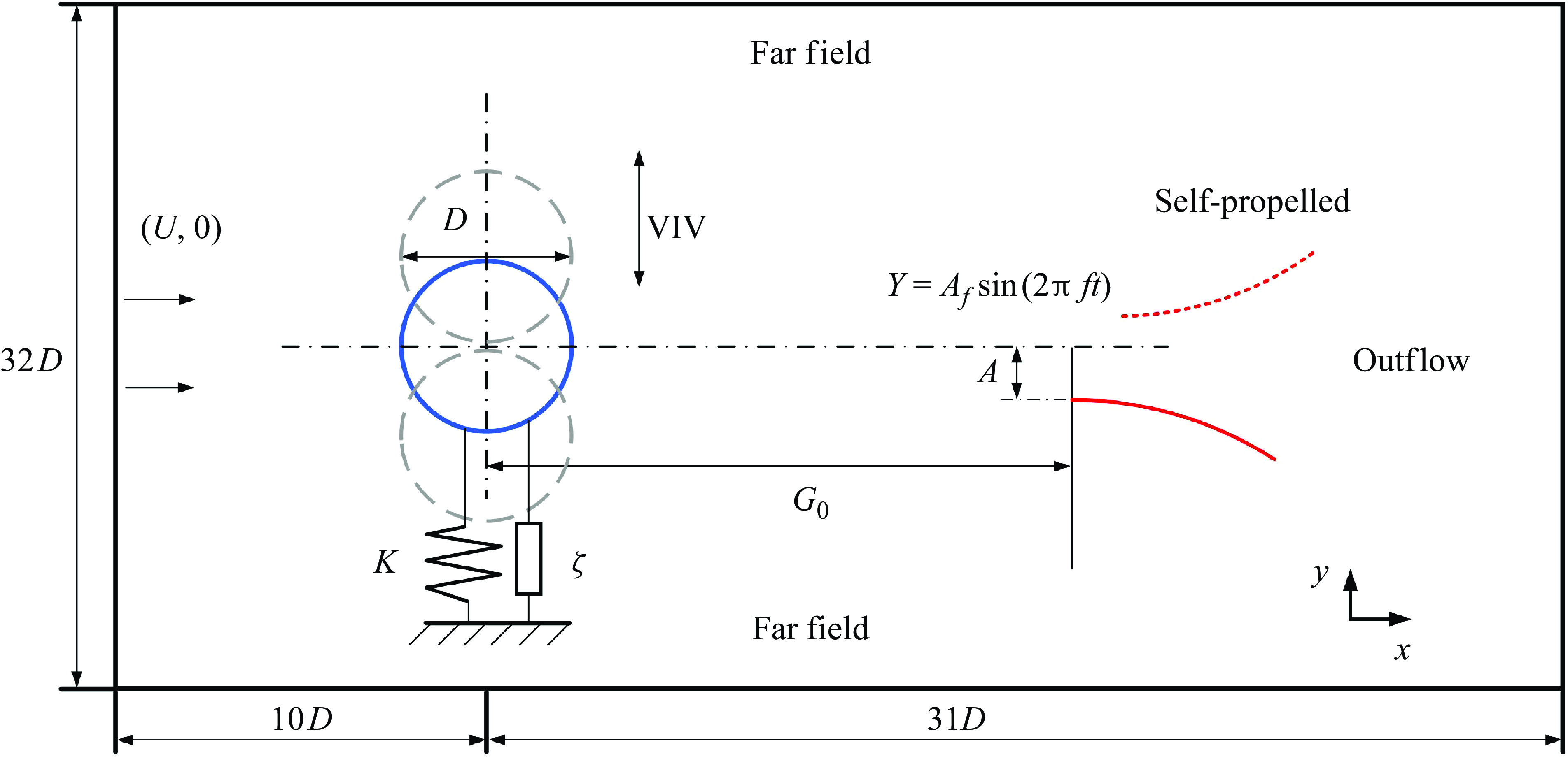
The self-propelled fish-like swimming system considered at present is illustrated in figure 1. An elastically supported cylinder, with diameter
 $D$
, undergoes free transverse vibrations (i.e. VIV) under the influence of incoming flow velocity
 $U$
. To enhance the cylinder vibration responses, the structural damping
 $\zeta$
is set to zero. In terms of representing the swimming fish behind the cylinder, we employ primarily a mechanical model based on the self-propelled two-dimensional flexible filament of length
 $L$
. In the present numerical simulations, a vertical oscillatory drive
 $Y_f(t)$
is imposed at the leading edge of the flexible filament. The resulting flexible deformation, apart from the leading edge, is determined by the fluid–structure interaction (FSI) between the filament and the fluid. This combined active and passive flexible flapping propulsion model is reasonable, as the wake structures generated by the flexible filament have been demonstrated to resemble those of real biological organisms. Furthermore, this approach is widely used to investigate the hydrodynamic characteristics of self-propelled systems (Zhu et al. Reference Zhu, He and Zhang2014; Park & Sung Reference Park and Sung2018; Peng et al. Reference Peng, Huang and Lu2018). The initial gap between the upstream VIV cylinder and the self-propelled swimmer is denoted as
 $G_0$
. Due to the self-propulsion mechanism of the swimmer, this gap continually varies, and we represent this variable as
 $G$
. The entire computational domain is
 $41D$
in length and
 $32D$
in width, with the cylinder placed at distance
 $10D$
from the inlet, and
 $16D$
from the upper and lower boundaries. The domain size is chosen to adequately capture the VIV response of the bluff body, with negligible blockage effects.
A schematic of the problem studied, with a self-propelled fin behind an elastically supported vibrating circular cylinder in a uniform flow.

2.2. Methodology
2.2.1. Numerical model
The governing equations for the fluid flow in the computational domain are solved by the two-dimensional Navier–Stokes equations, including mass and momentum conservation, as follows:
 \begin{align} \boldsymbol{\nabla} \boldsymbol{\cdot} \textbf {u} & =0, \end{align}
 \begin{align} \dfrac {\partial \textbf {u}}{\partial t}+(\textbf {u} \boldsymbol{\cdot} \boldsymbol{\nabla} )\textbf {u} &= -\boldsymbol{\nabla} p+\dfrac {1}{Re}\nabla ^2\textbf {u}+f_E, \end{align}
where
 $\textbf {u}$
and
 $p$
represent the non-dimensional velocity and pressure field, scaled based on the incoming velocity
 $U$
and
 $\rho _f U^2$
(with
 $\rho _f$
the density of the fluid), respectively. Here,
 $Re$
represents the Reynolds number, defined as
 $Re=UD/\nu$
, where
 $\nu$
is the viscosity. The term
 $t$
is the non-dimensional time, defined by the real time
 $T$
multiplying
 $U/D$
. Note that the right-hand term
 $f_E$
in (2.2) represents the Eulerian force, i.e. the FSI force for the fluid flow, non-dimensionalised by
 $\rho _f U^2/D$
. Introducing the force
 $f_E$
aims to apply the immersed boundary method to build the no-slip boundary of the solid. The Navier–Stokes equations are solved by the fractional step method on a staggered Cartesian grid. The velocity components and momentum forcing are defined on the staggered grid, whereas the pressure is applied at the centres of cells. Fully implicit time advancement is employed, with the Crank–Nicholson scheme used for the discretization of the diffusion and convection terms. Decoupling of velocity and pressure is achieved by block LU decomposition in conjunction with approximate factorization. Details of the approximate factorization can be found in Kim et al. (Reference Kim, Baek and Sung2002) and Huang et al. (Reference Huang, Shin and Sung2007).
As shown in figure 1, the governing equations for the self-propelled swimmer are based on the two-dimensional massive and inextensible flexible filament, or the fin model, of which the non-dimensional Lagrangian form can be written as
 \begin{equation} \rho _s\dfrac {\partial ^2 \textbf {X}}{\partial t^2}-\dfrac {\partial }{\partial s}\left(T_f^* \dfrac {\partial \textbf {X}}{\partial s}\right) + \dfrac {\partial ^2}{\partial s^2}\left(\gamma \dfrac {\partial ^2 \textbf {X}}{\partial s^2}\right) = -\textbf {F}, \end{equation}
where
 $s$
represents the arc length, and
 $\boldsymbol{X}$
(scaled by the reference fin length
 $L$
) is a function of
 $s$
and
 $t$
, denoting the Lagrangian position of the fin. The parameters
 $T_f^*$
and
 $\gamma$
represent, respectively, the dimensionless tension force and the bending rigidity, which are defined as
 \begin{equation} T_f^*=\dfrac {T_f}{\rho _s U^2},\quad \gamma =\dfrac {B}{\rho _sU^2L^2}, \end{equation}
where
 $T_f$
and
 $B$
are the dimensional tension and bending rigidity. In (2.3),
 $\rho _s$
represents the density difference between the fin and the surrounding flow (see Huang et al. (Reference Huang, Shin and Sung2007) for more details). Due to the inextensible assumption for the fin, we have
 \begin{equation} \dfrac {\partial \textbf {X}}{\partial s} \boldsymbol{\cdot} \dfrac {\partial \textbf {X}}{\partial s} = 1. \end{equation}
The tension force
 $T_f^*(s,t)$
can be solved implicitly by the Poisson equation derived from (2.3) and (2.5), for which the equation can be expressed as
 \begin{equation} \dfrac {\partial \textbf {X}}{\partial s} \boldsymbol{\cdot} \dfrac {\partial ^2}{\partial s^2}\left (T_f^*\dfrac {\partial \textbf {X}}{\partial s}\right ) = \dfrac {1}{2}\dfrac {\partial ^2}{\partial t^2}\left (\dfrac {\partial \textbf {X}}{\partial s} \boldsymbol{\cdot} \dfrac {\partial \textbf {X}}{\partial s}\right ) - \dfrac {\partial ^2 \textbf {X}}{\partial t \partial s} \boldsymbol{\cdot} \dfrac {\partial \textbf {X}}{\partial t \partial s}-\dfrac {\partial \textbf {X}}{\partial s} \boldsymbol{\cdot} \dfrac {\partial }{\partial s}( \textbf {F}_b-\textbf {F}), \end{equation}
where
 $\textbf {F}_b=- ({\partial ^2}/{\partial s^2}) (\gamma ({\partial ^2 \textbf {X}}/{\partial s^2}) )$
represents the bending force. The first term on the right-hand side of (2.6) should be zero, theoretically. This term is considered as an error in satisfying the inextensibility condition, and is corrected iteratively during the computation.
Following Zhu et al. (Reference Zhu, He and Zhang2014) and Park & Sung (Reference Park and Sung2018), a forced harmonic motion
 $Y_f(t)=A_f\sin (2\unicode{x03C0} ft)$
in the normal direction is applied on the first Lagrangian point of the fin for the self-propelled model, while all the other Lagrangian points undergo passive motion subjected to the FSI. Here,
 $A_f$
and
 $f$
denote the amplitude and flapping frequency, respectively. The swimmer, i.e. the flapping fin, can move freely horizontally, and we set its tail to be also free. Thus the following boundary conditions are imposed at the head and tail:
 \begin{equation} Y(t)|_{s=0}=A_f\sin (2\unicode{x03C0} ft+\theta ), \quad \left.\dfrac {\partial \textbf {X}}{\partial s}\right|_{s=0}=(1,0), \quad \left.\dfrac {\partial ^3X}{\partial s^3}\right|_{s=0}=0, \end{equation}
 \begin{equation} T_f^*|_{s=1}=0, \quad \left.\dfrac {\partial ^2 \textbf {X}}{\partial s^2}\right|_{s=1}=(0,0), \quad \left.\dfrac {\partial ^3 \textbf {X}}{\partial s^3}\right|_{s=1}=(0,0). \end{equation}
Here,
 $X$
represents the position information in the streamwise direction, which is different from the vector
 $\textbf {X}$
. By combining (2.3)–(2.8), the deformation and locomotion of the flexible fin in the self-propelled model can be solved. More details for the treatments on the numerical process can be found in Huang et al. (Reference Huang, Shin and Sung2007).
Now, let us solve the dynamics of the elastically supported rigid cylinder that placed in front of the self-propelled fin, as shown in figure 1. With the external fluid force (
 $F_v$
) exerted by the sum of vortex shedding and added mass, the governing equation of the VIV of the cylinder can be given by
 \begin{equation} M\ddot {Y_c}+C\dot {Y_c}+KY_c=F_v, \end{equation}
where
 $Y_c$
,
 $\dot {Y_c}$
and
 $\ddot {Y_c}$
are the displacement, velocity and acceleration of the moving cylinder, respectively. In (2.9),
 $M$
,
 $C$
and
 $K$
represent the structural mass, damping and stiffness, respectively. Here, we introduce the following dimensionless parameters:
 \begin{equation} \begin{array}{l} y = Y_c/D,\quad {m^*} = 4{M_s}/\unicode{x03C0} \rho {D^2},\quad C_{L}=2F_v/\rho U^2D,\quad \\[6pt] {U_r} = 2\unicode{x03C0} U/({\omega _s}D),\quad \zeta = {C_s}/(2M{\omega _s}), \quad \omega _s=\sqrt {K/M}, \end{array} \end{equation}
where
 $y$
,
 $m^*$
,
 $U_r$
,
 $C_{L}$
and
 $\zeta$
represent dimensionless displacement, mass ratio, reduced velocity, lift coefficient and damping ratio, respectively. Combining (2.9) and (2.10) yields the dimensionless equation for the VIV cylinder, i.e.
 \begin{equation} \ddot y + \frac {{{\kern 1pt} 4\unicode{x03C0} \zeta }}{{U_r}}\dot y + \frac {{4{\unicode{x03C0} ^2}}}{{U_{r}^2}}y = \frac {{2{C_L}}}{{{m^*}\unicode{x03C0} }}, \end{equation}
where (
 $\dot{\ }$
) represents the derivative with respect to the dimensionless time (
 $t=TU/D$
). In this study, we apply the Newmark-
 $\beta$
algorithm, with second-order accuracy, to solve (2.11), following Han et al. (Reference Han, Pan, Zhang, Wang and Tian2020) and Han & de Langre (Reference Han and de Langre2021).
2.2.2. Validations
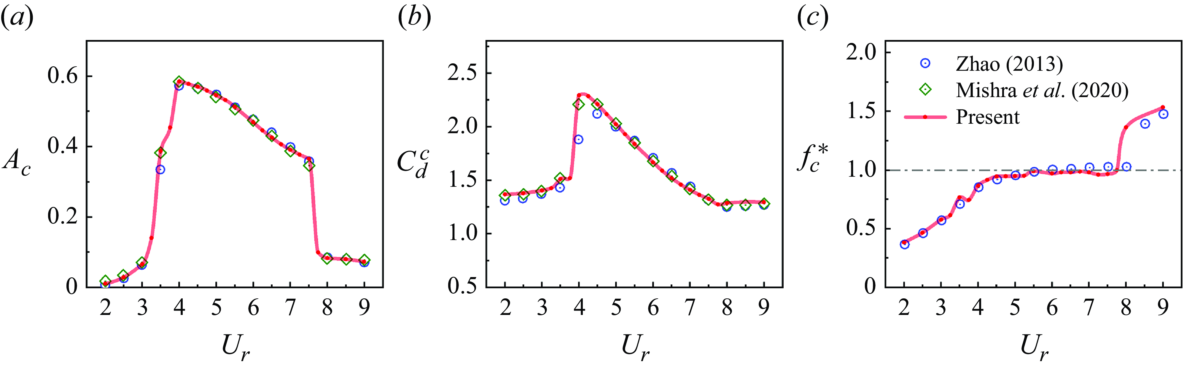
For validation of the current numerical method, three cases are computed and compared with published data, including the VIV of a bare circular cylinder, a single fin propelling through a quiescent fluid, and fish schooling dynamics. In Zhao (Reference Zhao2013) and Mishra et al. (Reference Mishra, Soti, Bhardwaj, Kulkarni and Thompson2020), the free vibration of a circular cylinder in flow was tested numerically, with mass ratio
 $m^*=2.546$
and Reynolds number
 $Re=150$
. Using the same parameters for both solid and fluid components, figure 2 presents a comparison between the current data and those taken from Zhao (Reference Zhao2013) and Mishra et al. (Reference Mishra, Soti, Bhardwaj, Kulkarni and Thompson2020). Good agreements can be found for the amplitude
 $A_c$
and frequency
 $f_c^*$
responses, as well as the mean drag coefficient
 $C_d^c$
in relation to the reduced velocity
 $U_r$
. Here, amplitude
 $A_c$
is defined as the maximum oscillation amplitude, while frequency
 $f_c^*$
is calculated as
 $f_c^*=f_{osc}/f_n$
, where
 $f_{osc}$
represents the oscillation frequency obtained through the fast Fourier transform (FFT) of displacement time histories, and
 $f_n=2\unicode{x03C0} \omega _s$
denotes the natural frequency. The computational domain, as depicted in figure 1, is filled with a uniformly distributed Eulerian grid of 2048 in the streamwise (
 $x$
) direction. In the normal (
 $y$
) direction, a uniform Eulerian grid is employed within the range
 $[-4, 4]$
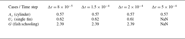
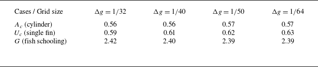
and is stretched otherwise, resulting in a total of 801 grid points. Therefore, the Eulerian grid contains 1 638 400 nodes. The Lagrangian grid on the circular cylinder consists of 157 points to match the resolution of the Eulerian grid in the fluid domain. Boundary conditions include velocity inlet, outflow and far-field conditions, with computational time step 0.00015. The selection of the grid resolution and time step size is based on convergence tests, as detailed in Appendix A. In figure 2, we can see that the current methodology effectively captures fluid forces and VIV responses, encompassing the lock-in range where high-amplitude oscillation occurs, with frequencies closely aligned to
 $f_n$
.
Variations of the VIV (a) amplitude response, (b) drag coefficient and (c) frequency response with the reduced velocity
 $U_r$
, obtained from the present method and published data (Zhao Reference Zhao2013; Mishra et al. Reference Mishra, Soti, Bhardwaj, Kulkarni and Thompson2020).

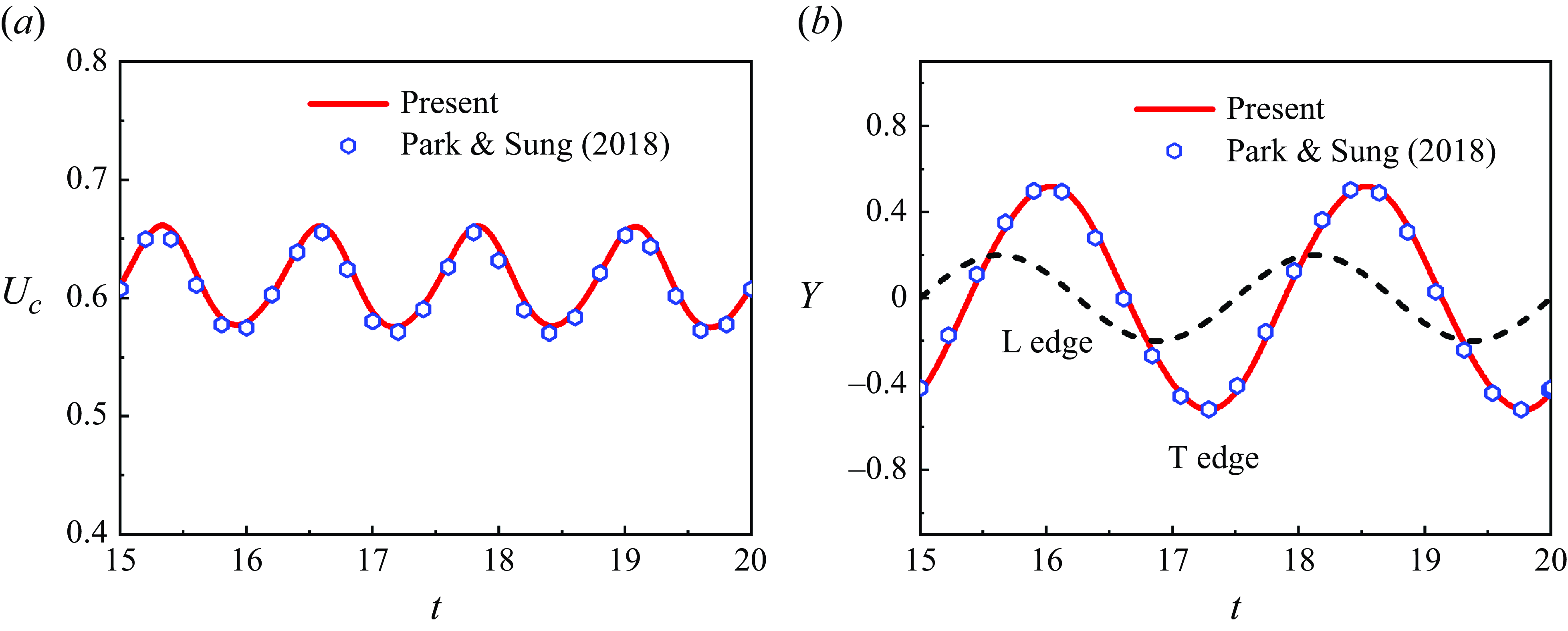
We further validate the current methodology by simulating the behaviour of a single fin in a quiescent fluid flow. Note that in this case, the fin propels itself through the FSI rather than flapping at a fixed position. The length of the fin is normalised to one unit, and it is discretised into 51 Lagrangian grids uniformly distributed along its length. To establish a quiescent fluid domain, the Neumann boundary condition is applied. Employing the parameters from Park & Sung (Reference Park and Sung2018), a comparison is presented in figure 3, focusing on the leading-edge (head) position, cruising speed and oscillation amplitude of the fin’s end tail. The cruising speed
 $U_c$
is defined based on the average velocity of the flexible fin, given by
 \begin{equation} U_c=\int _{0}^{L}\left |\dfrac {\partial X}{\partial t}\right |{\rm d}s. \end{equation}
Time histories of (a) the cruising speed
 $U_c$
(computed by (2.12)) and (b) the passive flapping amplitude of the trailing edge of the fin, obtained by the present method and from Park & Sung (Reference Park and Sung2018). In (b), the black dashed line represents the imposed amplitude of the leading edge of the fin.

The results in figure 3 demonstrate that the present model effectively captures both the locomotion speed and the deformations of a flexible self-propelled fin in fluid flow.
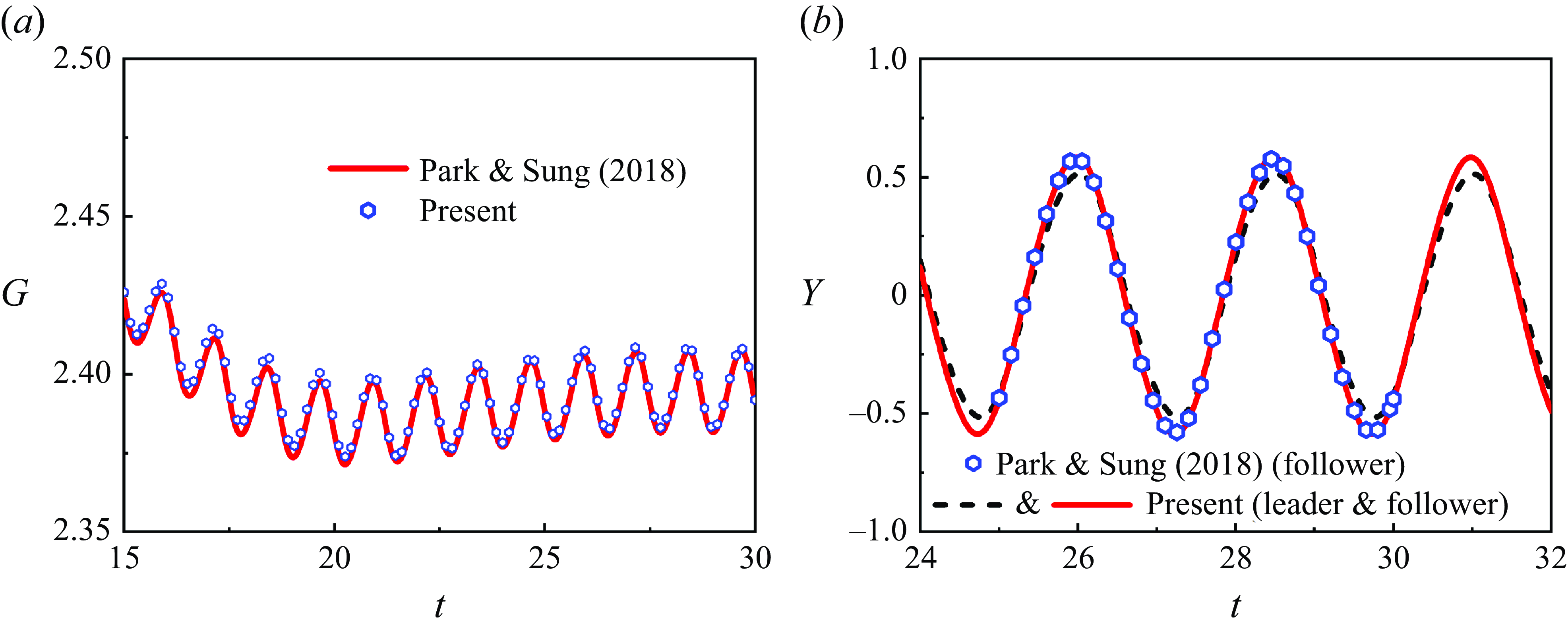
As the present study focuses on a swimmer navigating unsteady vortices generated by an upstream obstacle, it is necessary to validate whether the proposed methodology accurately captures the dynamics of the fin, particularly its position variations within unsteady wakes. For this, a comparison is made between the simulated schooling dynamics of fins and the data reported in Park & Sung (Reference Park and Sung2018). Specifically, two tandem flexible self-propelled fins, referred to as the leader and follower, are considered, with their physical parameters matching those in Park & Sung (Reference Park and Sung2018). The two fins are initialised with a gap
 $G_0 = 2$
, which dynamically adjusts due to fluid–structure–vortex interactions. Figure 4(a,b) show the time evolution of the dynamic distance between the two fins and the flapping amplitude of their trailing edges, respectively.
Time histories of (a) the dynamic gap
 $G$
between the two flexible self-propelled fins, and (b) the flapping amplitude of the trailing edge of the fins, as obtained using the present method and compared with the results from Park & Sung (Reference Park and Sung2018).

From figures 2, 3 and 4, it is evident that the present method accurately simulates the dynamics of a freely vibrating cylinder, a self-propelled fin in fluid flow, and a fin in unsteady wakes. This aligns with the central theme of the current research, which focuses on the study of a swimmer in the wake of a vortex-induced vibrating cylinder.
3. Results
Using the model described in § 2.2, a series of simulations is conducted to investigate the dynamics of a self-propelled fin in the wake of a VIV circular cylinder. The simulations encompass various initial gaps
 $G_0$
, incoming reduced velocities
 $U_r$
, and phases of the release moment
 $\phi$
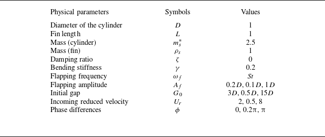
. The tested parameters are outlined in table 1, and Reynolds number 200 is maintained. In this section, the analysis proceeds in three stages. First, we categorise the vortex shedding mode in VIV, laying the foundation for understanding the subsequent swimming behaviours. Subsequently, the swimming behaviours associated with different VIV wakes are investigated. Note that fully developed VIV wakes, generated at different incoming reduced velocities, are used as the initial flow field for releasing the self-propelled flexible fin. Finally, the section concludes with an exploration of the underlying mechanisms governing the swimming characteristics. This involves a detailed analysis of the hydrodynamics, the vortex interactions, and the energy transfer characteristics.
Parameters tested in the present numerical simulations.

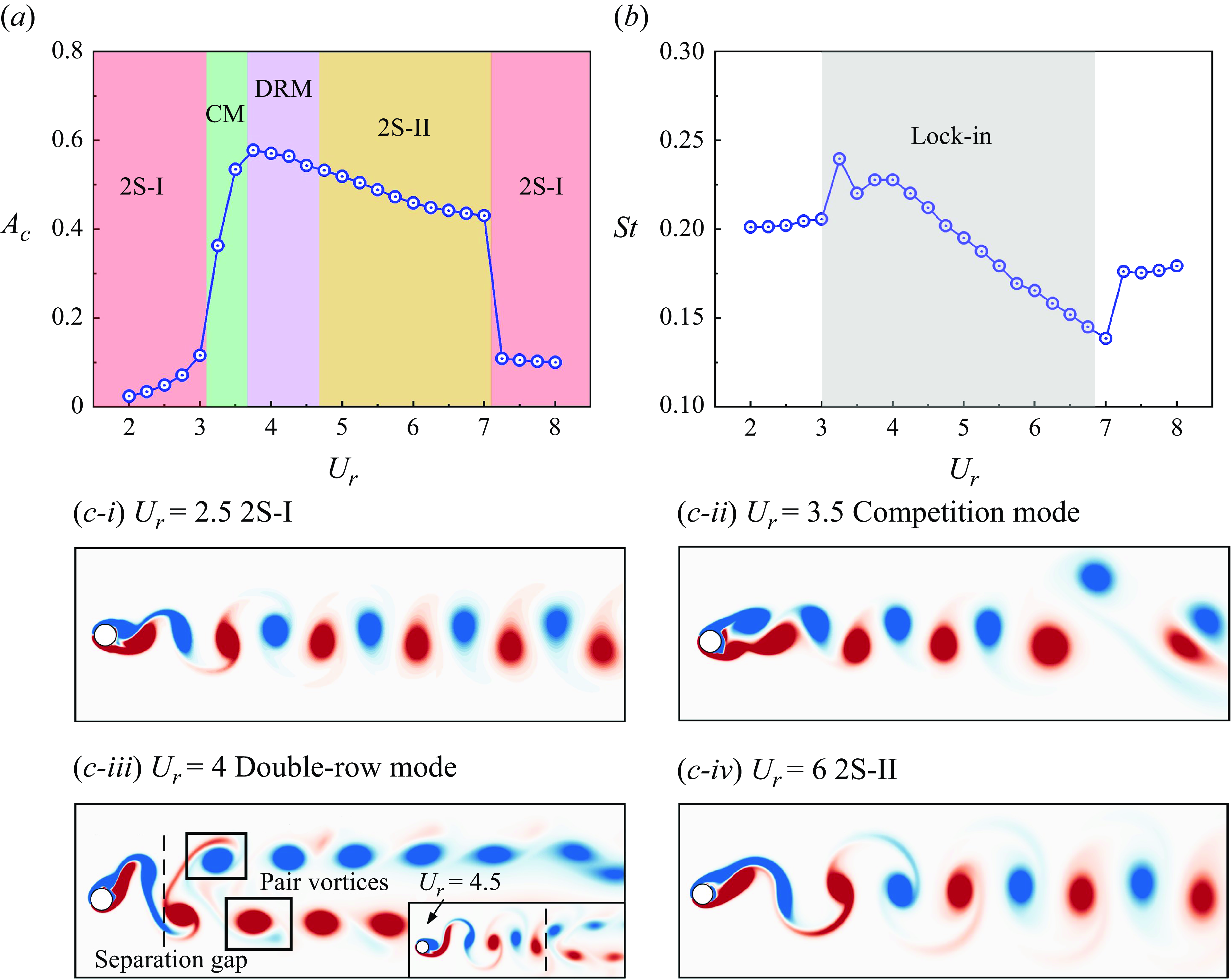
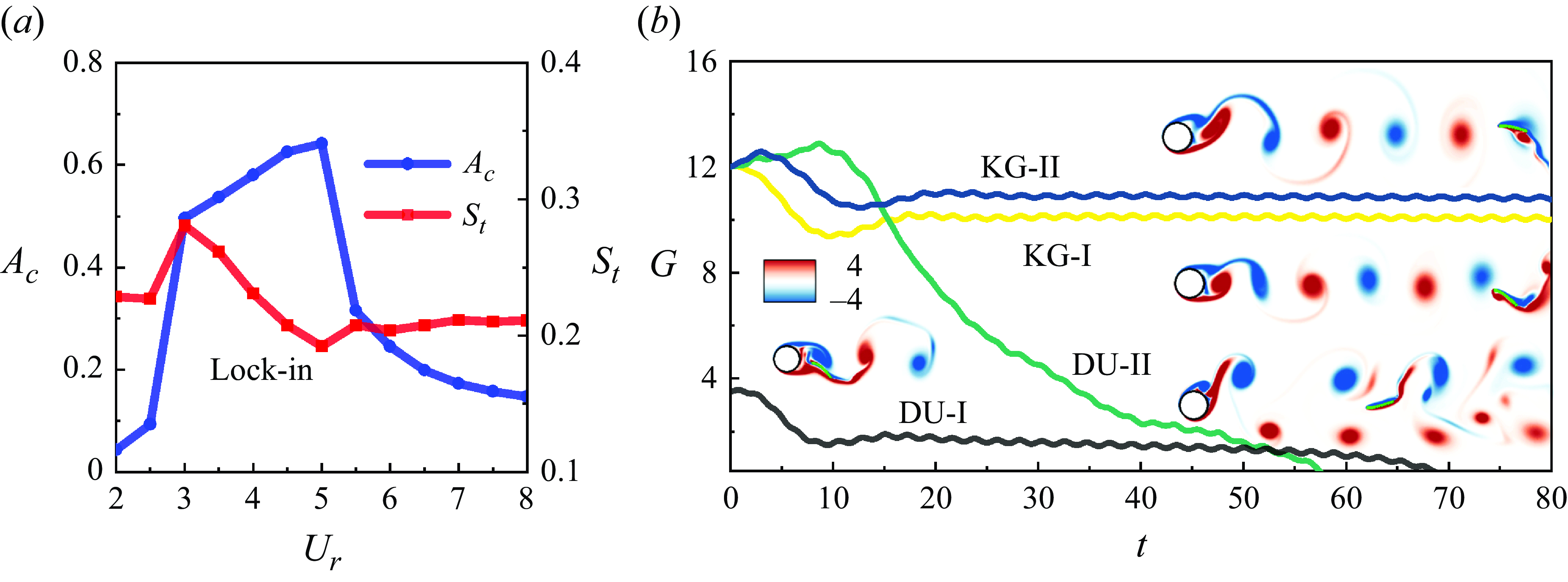
(a) Amplitude, (b) vortex shedding frequency, and (c) wake modes of VIV of a bare circular cylinder at
 $Re=200$
, with mass and damping ratio
 $m_s^*=2.5$
and
 $\zeta =0$
, respectively.

3.1. The VIV wakes
At a certain Reynolds number, a Karman vortex street can manifest behind a stationary circular cylinder. When the bluff body is free to vibrate, it may induce various vortex shedding modes, such as 2S, 2P, P+S, and so on, contingent upon the reduced velocity
 $U_r$
and the Reynolds number
 $Re$
(Williamson & Govardhan Reference Williamson and Govardhan2004). Consequently, the swimmer in a VIV wake can exhibit diverse characteristics, influenced by interactions among different vortex shedding modes. To classify the VIV wake at the present tested parameters, we initially conduct simulations on a bare VIV circular cylinder, featuring mass ratio
 $m_s^*=2.5$
and zero damping. The reduced velocity
 $U_r$
varies from 2 to 8 with increment 0.25. Figure 5(a) illustrates the amplitude responses, while in figure 5(b), we plot the Strouhal number (
 $St$
) in relation to
 $U_r$
, obtained via the FFT of the lift force time histories. Combining figure 5(a,b) allows the identification of the lock-in range, characterised by high-amplitude oscillations and decreasing
 $St$
, as marked in the grey region of figure 5(b). Figure 5(c-i–c-iv) showcase typical vortex shedding modes in the VIV wake, denoted as 2S-I, competition mode (CM), double-row mode (DRM) and 2S-II mode, respectively. In the 2S-I mode, the vibration amplitudes are relatively small, rendering the wake akin to the Karman street generated behind a fixed cylinder. This mode forms with positive and negative vortex shedding alternately in a cycle of vibration. As
 $U_r$
increases, the typical double-row mode emerges in figure 5(c-iii), where negative and positive vortices in the wake separate into two rows at a specific position behind the circular cylinder. Notably, in the double-row mode, the separation gap also increases with
 $U_r$
, which is seen at
 $U_r=4$
and 4.5, for instance. Between the reduced velocities corresponding to the 2S-I and double-row modes, the competition mode arises, characterised by chaotic vortex shedding, with vortices being generated in an alternating fashion akin to 2S-I and double-row modes. In figure 5(c-iv), another vortex shedding mode is identified, labelled as 2S-II or the aligned 2S. Essentially, 2S-II resembles 2S-I in figure 5(c-i); however, the vertical spacing between neighbouring vortices is minimal, while the horizontal spacing exceeds that of 2S-I. These features contribute to a distinct swimming mode of the self-propelled fin, as elaborated upon later. Morse & Williamson (Reference Morse and Williamson2009) experimentally tested the wake of an oscillating circular cylinder, with forced motion. At a certain range of normalised wavelength (i.e. the frequency), the wake might change from 2S to 2P with the increase of the amplitude, and there would be a transition mode of
 $\rm 2P_0$
between them. The
 $\rm 2P_0$
transition mode shows a way that two pairs of vortices are shed in a period of oscillation; however, the two vortices are not in the same level, and the weaker one will be quickly merged by another one. The above features indicate that the double-row mode defined at present is identical to the
 $\rm 2P_0$
model. However, because of a relative low Reynolds number applied here, not enough energy can be absorbed by the VIV cylinder to increase its amplitude then reach the requirements of the real 2P vortex shedding mode. Finally, based on the vortex shedding modes delineated in figure 5(c), we categorise the VIV responses into different branches, as depicted in figure 5(a).
3.2. The swimming modes
Exploring the swimming behaviours of a self-propelled fin in various VIV wakes would be of interest. Furthermore, investigating potential energy-saving strategies employed by the swimmer, particularly in the context of vortex interactions, adds a valuable perspective to the study. To address this objective, we conduct tests involving different reduced velocities
 $U_r$
and initial gaps
 $G_0$
at
 $Re=200$
. In this subsection, the remaining parameters are constant, with the flapping amplitude set at
 $A_f=0.3$
(a parameter analysis of
 $A_f$
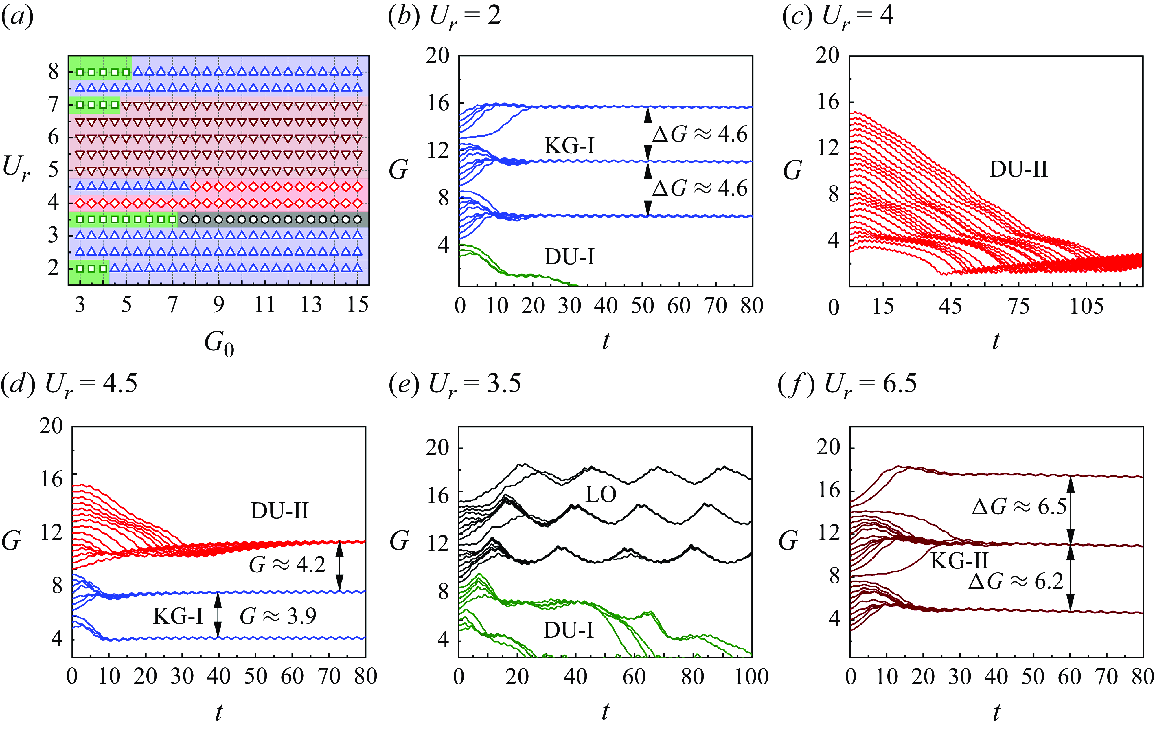
can be found in Appendix B). The flapping frequency is aligned with the vortex shedding frequency of the upstream VIV cylinder, as determined in figure 5(b). Employing previously validated methods, along with established grid and time step settings, we present the total set of tested cases in figure 6(a). Different colours in the figure signify distinct swimming modes, including drifting upstream I (DU-I) mode, Karman gait I (KG-I) mode, large oscillation (LO) mode, Karman gait II (KG-II) mode, and drifting upstream II (DU-II) mode. Each mode will be discussed individually in this subsection. Figure 6(b–f) depict the gap
 $G$
(i.e. the position) of the self-propelled fin swimming under five representative reduced velocities (i.e.
 $U_r=2$
, 3.5, 4, 4.5 and 6.5), encompassing all the identified swimming modes. Notably, the gap
 $G$
between the cylinder and the fin dynamically evolves with time, eventually converging to distinct solutions in most cases.
(a) The tested cases with various reduced velocities
 $U_r$
and initial gaps
 $G_0$
, categorised by five swimming modes. Green square indicates DU-I, blue triangle (up) indicates KG-I, brown triangle (down) indicates KG-II, red diamond indicates DU-II, black circle indicates LO. (b–f) Time histories of the dynamic gap
 $G$
between the VIV cylinder and the fin’s leading edge with
 $U_r=2$
, 4, 4.5, 3.5 and 6.5, respectively.

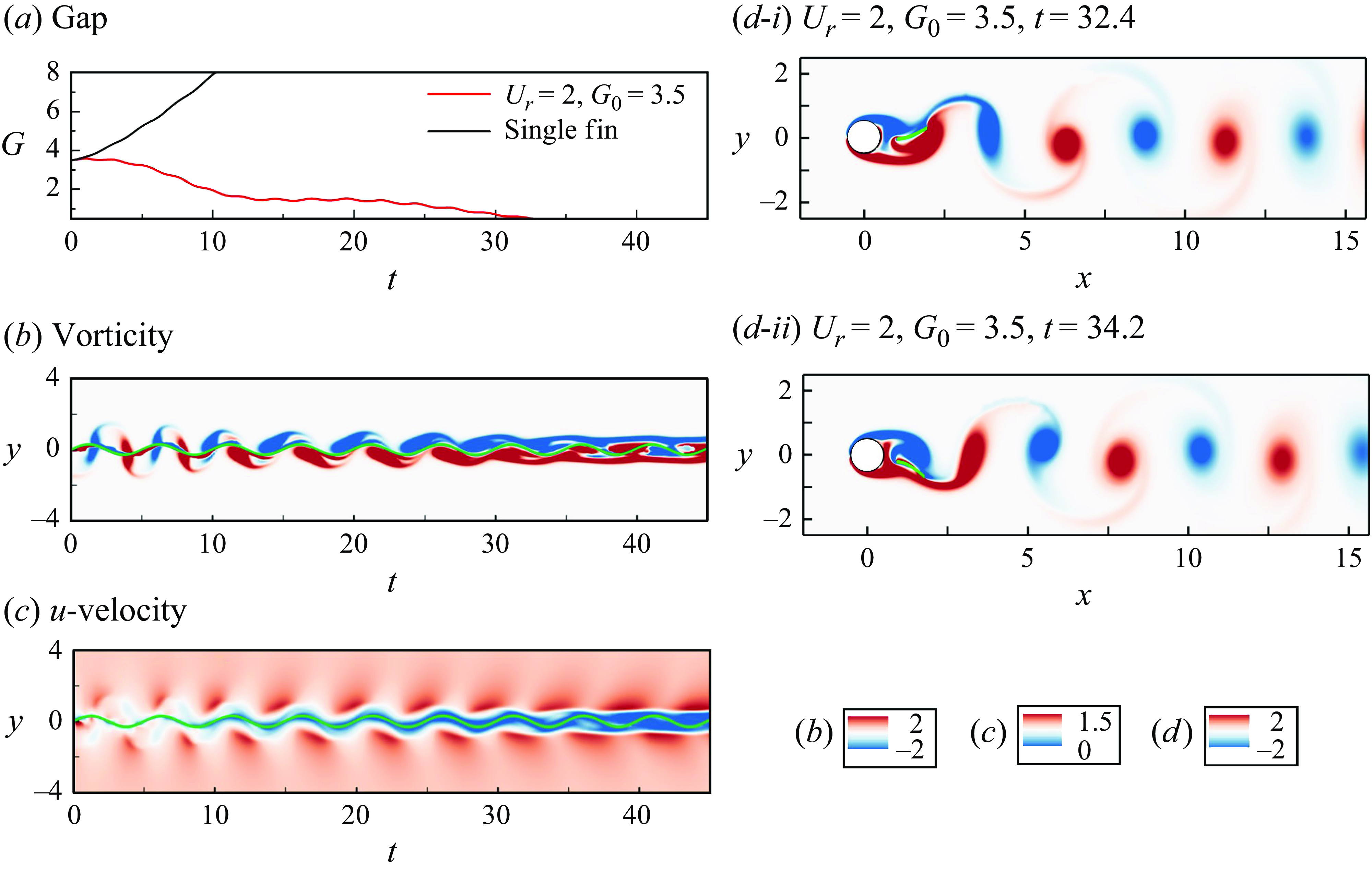
Time evolutions of the (a) position, (b) vorticity and (c) streamwise velocity, at the leading edge of the self-propelled flexible fin in the DU-I mode, with
 $U_r=2$
and
 $G_0=3.5$
. The trajectory of the leading edge is marked with a green line in (b) and (c). (d) Vorticity contours at different instants. More details can be found in supplementary movie 1.

3.2.1. Drifting upstream I (DU-I) mode, with the suction zone
In figure 6(b,e), the green lines representing the DU-I mode reach a very small value with time
 $t$
, signifying that the fin propels upstream and ultimately collides with the VIV cylinder. Considering a typical case in DU-I mode at
 $G=2$
and
 $U_r=2$
in figure 6(b), we compare the
 $G$
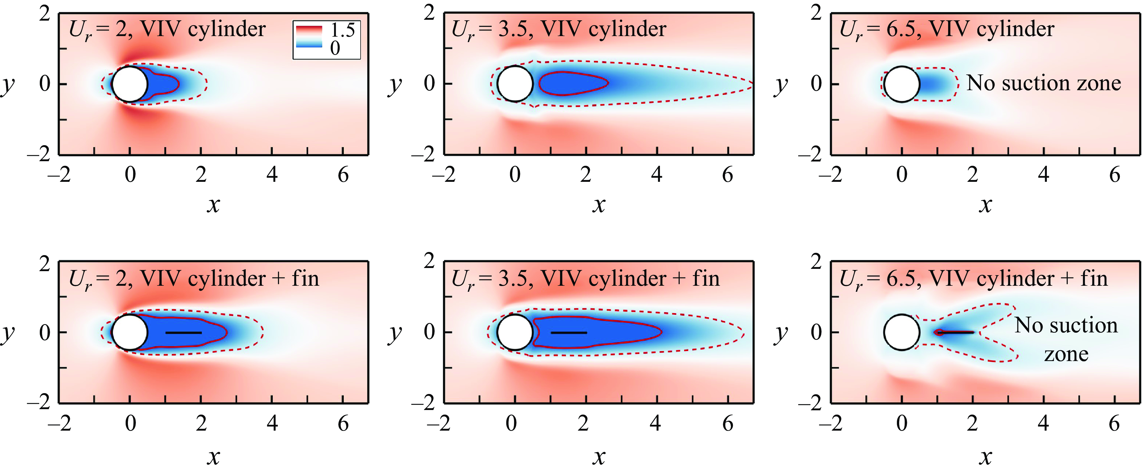
curves with a case lacking the upstream cylinder in figure 7(a). It is evident that without the upstream bluff body, the fin drifts downstream rather than upstream (see black line), indicating that the swimmer gains hydrodynamic benefits in the DU-I mode. This phenomenon is attributed to the mechanism wherein a suction zone forms nearly behind a bluff body (Eldredge & Pisani Reference Eldredge and Pisani2008). Consequently, the streamwise velocity in the suction zone is much lower than the free-stream velocity
 $U$
, or may even be negative. This explains why the DU-I mode occurs only near the upstream VIV cylinder. The aforementioned information is evident in our numerical results presented in figure 7(b,c), which depict the time evolution of vorticity and streamwise velocity along the vertical line at the leading edge of the fin, respectively. The results in figure 7(c) highlight a substantial reduction in the streamwise velocity within the swimming region of the leading edge, particularly after
 $t=15$
when the fin is positioned at
 $G\approx 2$
. We define the suction zone as a region where the mean streamwise velocity is negative. Figure 8 illustrates the mean streamwise velocity and the corresponding suction and low-velocity zones of a VIV cylinder at different reduced velocities
 $U_r$
, with or without a fin placed near the upstream body (
 $G_0=0.5$
). Notably, the solid and dashed lines represent the isolines
 $\bar {u}=0$
and
 $\bar {u}=0.5U_{\infty }$
, respectively. The results indicate that having a fin behind a VIV cylinder can enlarge the reduction region of the flow velocity. Interestingly, for
 $U_r$
ranging from 4 to 6.5, the suction zone diminishes, as seen in figure 8. This explains the absence of the DU-I mode at these incoming reduced velocities (figure 6
a).
Time-averaged streamwise velocity field of a VIV cylinder without (upper row) and with (lower row) the fin placed at
 $G_0=0.5$
, with different reduced velocities
 $U_r$
. The solid and dashed lines represent the isolines
 $\bar {u}=0$
and
 $\bar {u}=0.5U_{\infty }$
, respectively.

3.2.2. Karman gait I (KG-I) mode, with the fin moving around the vortices
At
 $U_r=2$
(figure 6
b), with the initial gap ranging from 4.5 to 15, the self-propelled fin demonstrates three stable positions regardless of the initial release positions
 $G_0$
. Moreover, the distances between the stable states are consistent, measuring
 $\Delta G=4.6$
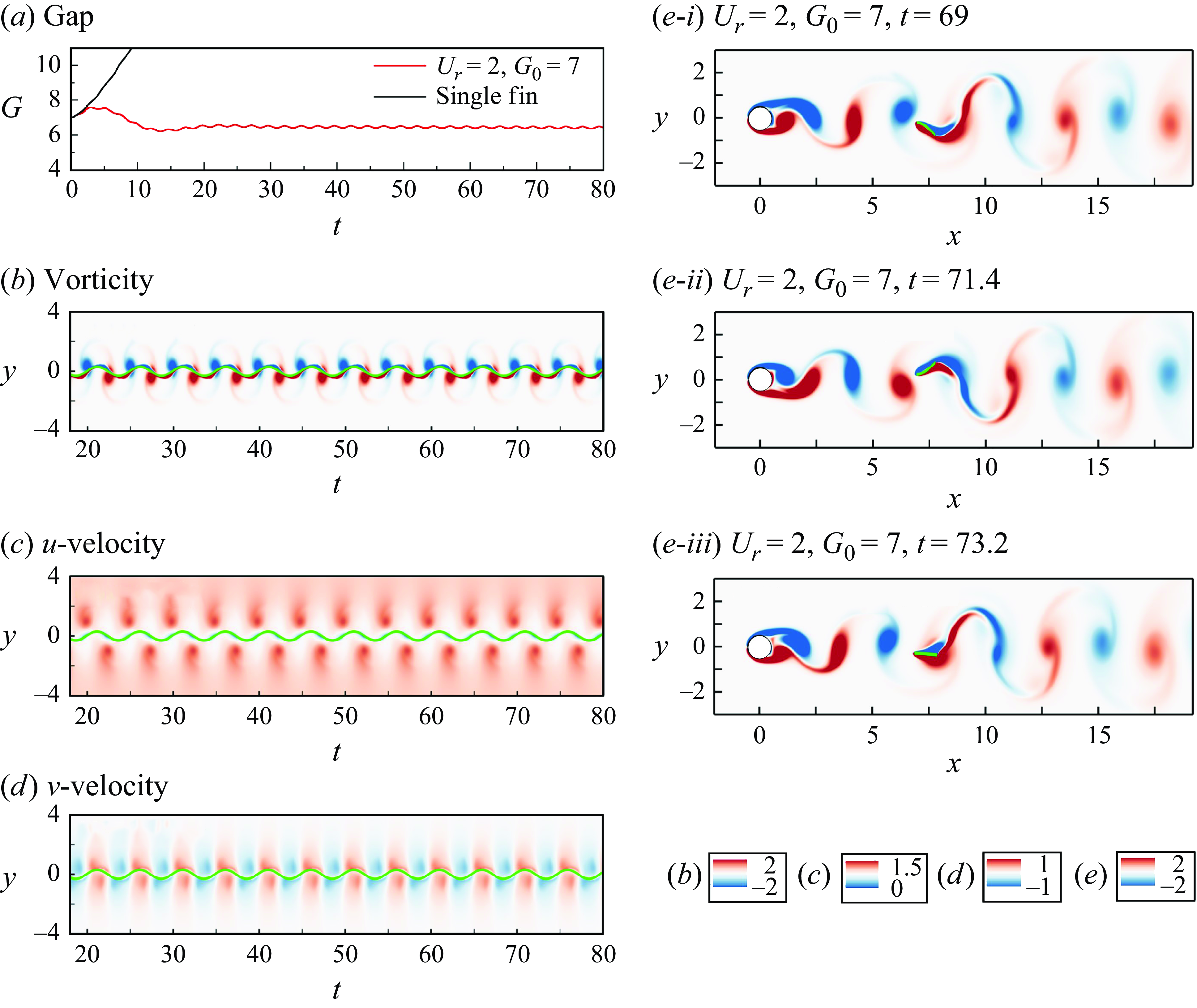
. It is noteworthy that this value closely resembles the gap between two adjacent positive/negative vortices in two vortex shedding periods, as depicted in figure 5(c-i). This suggests that the distances of converged positions are indeed determined by the vortex gap. This phenomenon mirrors the findings of previous cases of locomotion behind a stationary cylinder (Park et al. Reference Park, Kim and Sung2016; Wang et al. Reference Wang, Huang and Lu2019). The similarity arises because the VIV amplitude here is small, rendering its wake comparable to the classic Karman vortex street behind a fixed cylinder. In comparison to scenarios where the swimmer (without the cylinder) is constantly pushed backwards by the flow current, the Karman gait I can also be regarded as a hydrodynamic benefit mode. To further elucidate the characteristics of the KG-I mode, we present the time evolutions of vorticity, streamwise and normal velocities along the vertical line at the leading edge of the fin in figure 9. Several notable features emerge. First, the self-propelled fin consistently moves around the vortex cores, aligning with previous findings from systems with a stationary cylinder (Liao et al. Reference Liao, Beal, Lauder and Triantafyllou2003; Park et al. Reference Park, Kim and Sung2016). This pattern is also discernible in the instantaneous vorticity fields in figure 9(e). The self-propelled fin moves around the negative vortex from a lower flapping position to a higher one, and from a higher to a lower flapping position for the positive vortex. Additionally, the vortices generated by the circular cylinder merge with those of the swimmer in the wake, and the new vortices continue to shed in a 2S pattern. Second, owing to the vortex shedding from the VIV cylinder, the fin benefits from the reduction of the streamwise velocity, although the reduction is not as pronounced as observed in the suction zone (see figure 8). Third, in addition to the benefit from the streamwise velocity, the fin can also gain hydrodynamic advantages in the vertical direction. This is evident from figure 9(d), where, during the peaks of the flapping motion, the leading edge of the fin interacts with a positive vertical velocity. Conversely, the leading edge of the fin is in the negative vertical velocity region when it descends to wave bottoms. These results suggest that the flapping of the leading edge is in phase with the normal velocity of the fluid flow in front of the fin, resulting in a reduction in the power needed for the flapping motion.
Time evolutions of the (a) position, (b) vorticity, (c) streamwise velocity and (d) normal velocity along the vertical line, at the leading edge of the self-propelled flexible fin, with
 $U_r=2$
and
 $G_0=7$
in the KG-I mode. The trajectory of the leading edge is marked with a green line. (e) Vorticity contours at different instants. More details can be found in supplementary movie 2.

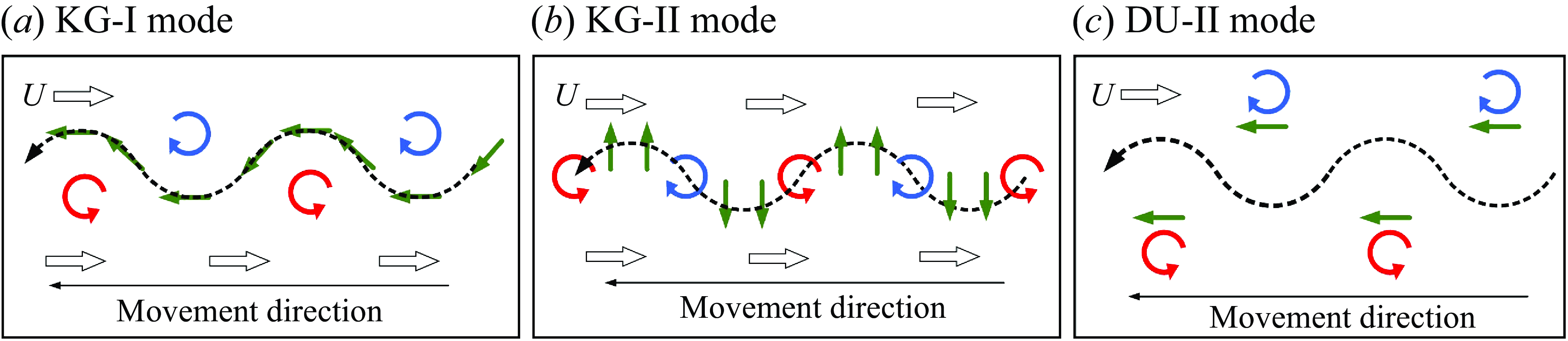
To provide a clear visualization of the swimming mode and elucidate the energy savings mechanism, figure 10(a) presents a schematic illustrating the interactions between the vortices and the leading edge of the KG-I mode. Figure 10(b,c) depict schematics for other modes that will be discussed later. The trajectory of the leading edge is represented by the black dashed line in the figure. Clockwise red and anticlockwise blue circular arrows signify positive and negative vortical structures, respectively. During the process of vortex structure generation and evolution, the surrounding fluid rotates along with the structure, forming a vortex-induced velocity aligned with the direction of rotation. Due to the distinct rotational directions of vortex structures, alternating positive and negative vortices create a consistent region between their structures. In this region, the vortex-induced velocity is oriented opposite to the incoming flow direction, as indicated by the green arrows. In the KG-I mode, the self-propelled fin manoeuvres between the vortex cores, and its trajectory closely follows the vortex-induced fluid motion. Consequently, the fin can benefit from hydrodynamic advantages in this mode, taking advantage of the alternating positive and negative vortices to navigate and potentially save energy.
Schematics of the interaction between the self-propelled fin and the vortical structures in the (a) KG-I, (b) KG-II and (c) DU-II modes. The clockwise and anticlockwise circular arrows represent the positive and negative vortices, respectively. The solid green and hollow black arrows represent the direction of the vortex-induced fluid motion and free-stream velocity, respectively. The trajectories of the leading edge of the flexible fin is drawn by a black dashed line, showing different characteristics for different swimming modes.

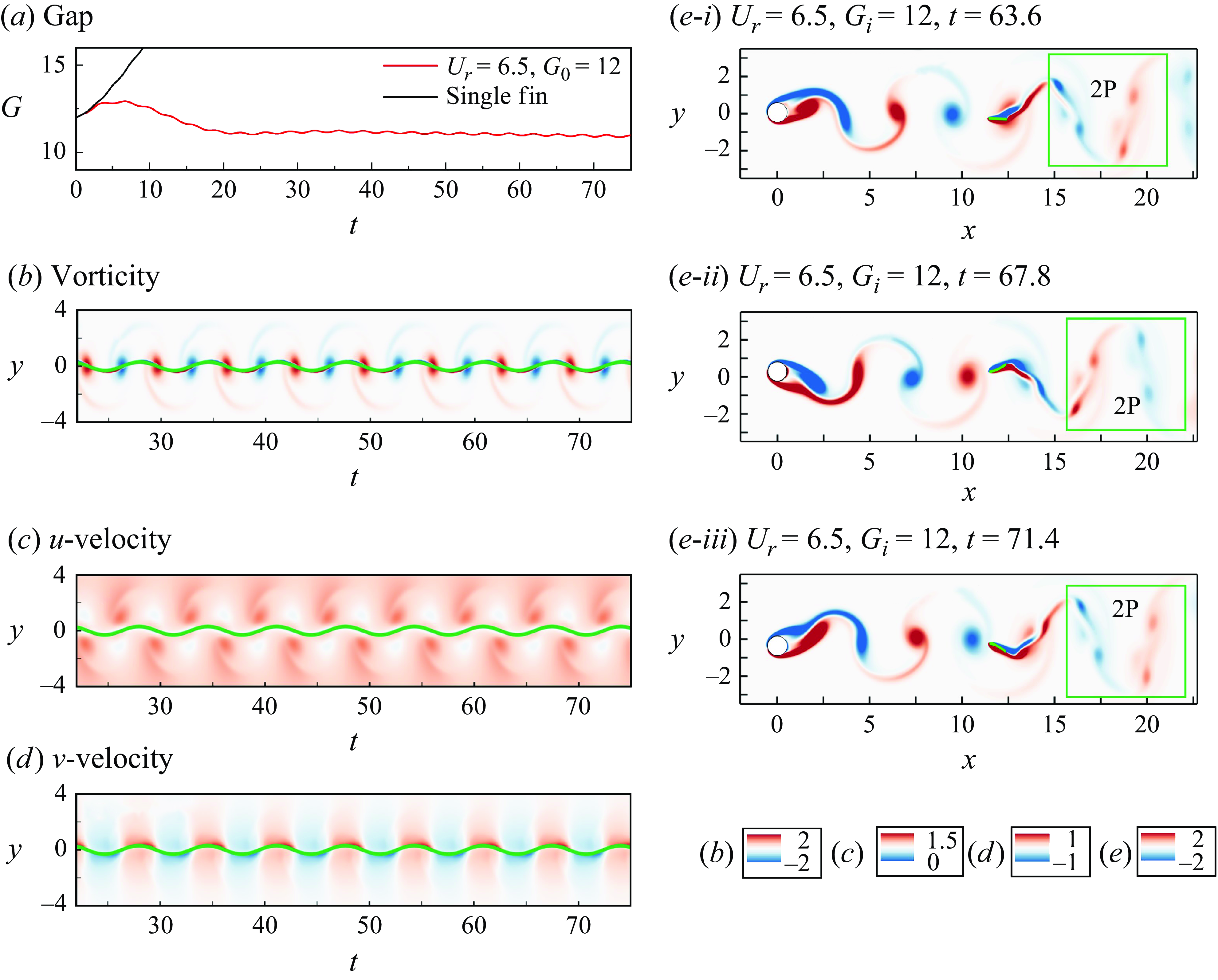
Time evolutions of the (a) position, (b) vorticity, (c) streamwise velocity and (d) normal velocity along the vertical line, at the leading edge of the self-propelled flexible fin, with
 $G=12$
and
 $U_r=6.5$
in the KG-II mode. (e) Vorticity contours at different instants. The green square represents the symmetry breaking zone in the wake. More details can be found in supplementary movie 3.

3.2.3. Karman gait II (KG-II) mode, with the fin crossing through the vortices
In figure 5(a), as the reduced velocity increases from 4.5 at the end of the double-row mode to 7.25 at the beginning of the desynchronization region, the 2S-II mode is formed by a VIV cylinder. The corresponding swimming mode, named Karman gait-II (KG-II) mode, is illustrated in figure 6(f). In the KG-II mode, the swimmer maintains a stable position behind the VIV cylinder, and computational results converge to several solutions regardless of the initial release gaps
 $G_{0}$
. Although the observed phenomena share similarities with those found in KG-I mode as depicted in figure 6(b), the swimming behaviours and underlying mechanisms between KG-I and KG-II are distinct.
Considering a typical case in the KG-II mode with
 $U_r=6.5$
and
 $G=12$
, figure 11 (b–d) show the time evolutions of vorticity, streamwise and normal velocities along the vertical line, while figure 11(a) provides the position at the leading edge of the fin. In the KG-II mode, the leading edge of the fin precisely crosses through the vortex cores rather than around them, as observed in the KG-I mode. As a fin without a VIV cylinder cannot maintain a stable position and would be carried downstream by the fluid flow, the KG-II mode can also achieve hydrodynamic advantages. In previous studies, Liao et al. (Reference Liao, Beal, Lauder and Triantafyllou2003) and Park et al. (Reference Park, Kim and Sung2016) indicated that a swimmer can gain hydrodynamic advantages and save costs only by moving around the vortex cores in the wake of a bluff cylinder, aligning with the present KG-I mode. In the new KG-II mode, we propose that the self-propelled fin can benefit from the normal velocity induced by vortices to save energy by crossing through the vortex cores. As shown in figure 11(d), the locomotion of the fin’s leading edge is almost perfectly in phase with the vertical velocity of the fluid flow. Moreover, compared to other swimming modes, both the magnitude and fluctuation of the environmental normal velocity in the KG-II mode are larger. This explains why a fin in the KG-II mode can save energy, even though it may not experience a reduction in streamwise velocity. Figure 11(e) presents the instantaneous vorticity field of the system in the KG-II mode, clearly showing that the swimmer crosses through the negative and positive vortex cores during the upper and lower strokes, respectively. In addition, the upstream VIV vortices can be split into smaller ones by the fin, resulting in a pair of vortices being shed in one cycle of the fin’s propulsion, demonstrating a 2P mode.
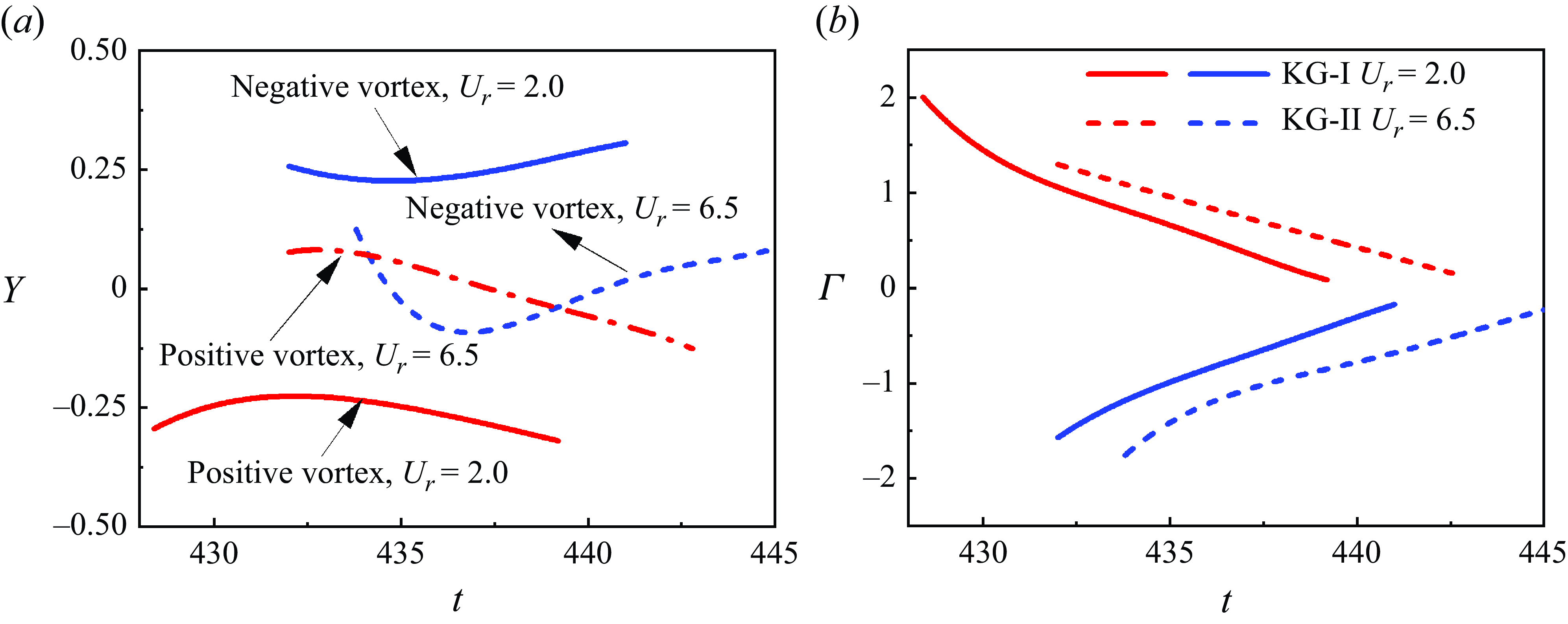
The occurrence of different swimming modes is determined primarily by the incoming flow conditions, particularly the vortices present in the upstream VIV wake. To further elucidate the differences in swimming behaviours between the KG-I and KG-II modes of a self-propelled fin, we analyse the positions of the vortex cores generated by a single VIV cylinder over time, as well as the circulation representing vortex intensities, as shown in figure 12. The reduced velocities considered are
 $ U_r = 2$
and
 $ U_r = 6.5$
, which correspond to the upstream wake conditions associated with the KG-I and KG-II modes, respectively. For each
 $ U_r$
, a pair of positive and negative vortices from a fully developed VIV wake near the position at
 $ G = 6$
is selected for time tracing. The results show that, compared to the KG-I mode, the positive and negative vortices in the KG-II mode are more closely aligned along a straight line. As a result, the vortex-induced velocities of adjacent vortices are more likely to be in phase in the vertical direction (see figure 11
d). In this configuration, the downstream flexible fin can benefit by crossing through the vortex cores, as shown in figure 11(b). In contrast, in the KG-I mode, the positive and negative vortices are vertically spaced, causing the vortex-induced velocities from adjacent vortices to be directed between the two vortices, with both streamwise and vertical components. This configuration results in an optimal energy path that moves around the vortex cores, as depicted in figure 9(b). Moreover, the vortex circulation encountered in the KG-II mode is stronger (see figure 12
b), leading to a higher vortex-induced velocity. This is one of the possible reasons why the energy conversion efficiency in the KG-II mode is higher than in the KG-I mode, a topic that will be discussed further in § 3.3.
Figure 10(b) presents a schematic illustrating the interaction of the vortices and the leading edge in the KG-II mode. Comparing to the KG-I mode in figure 10(a), due to the small normal and large streamwise distances among vortices, the vortex-induced velocity of the surrounding fluid flow aligns in the same normal direction, as indicated by the green arrows. By adjusting its position, the self-propelled fin can find a path crossing through the vortex cores, benefiting from the vortex-induced velocity and saving energy.
Time histories of the (a) positions and (b) circulations of the vortices generated by a bare VIV cylinder at
 $ U_r = 2$
(conditions for the occurrence of the KG-I mode) and
 $ U_r = 6.5$
(conditions for the occurrence of the KG-II mode).

3.2.4. Drifting upstream II (DU-II) mode, with symmetry breaking
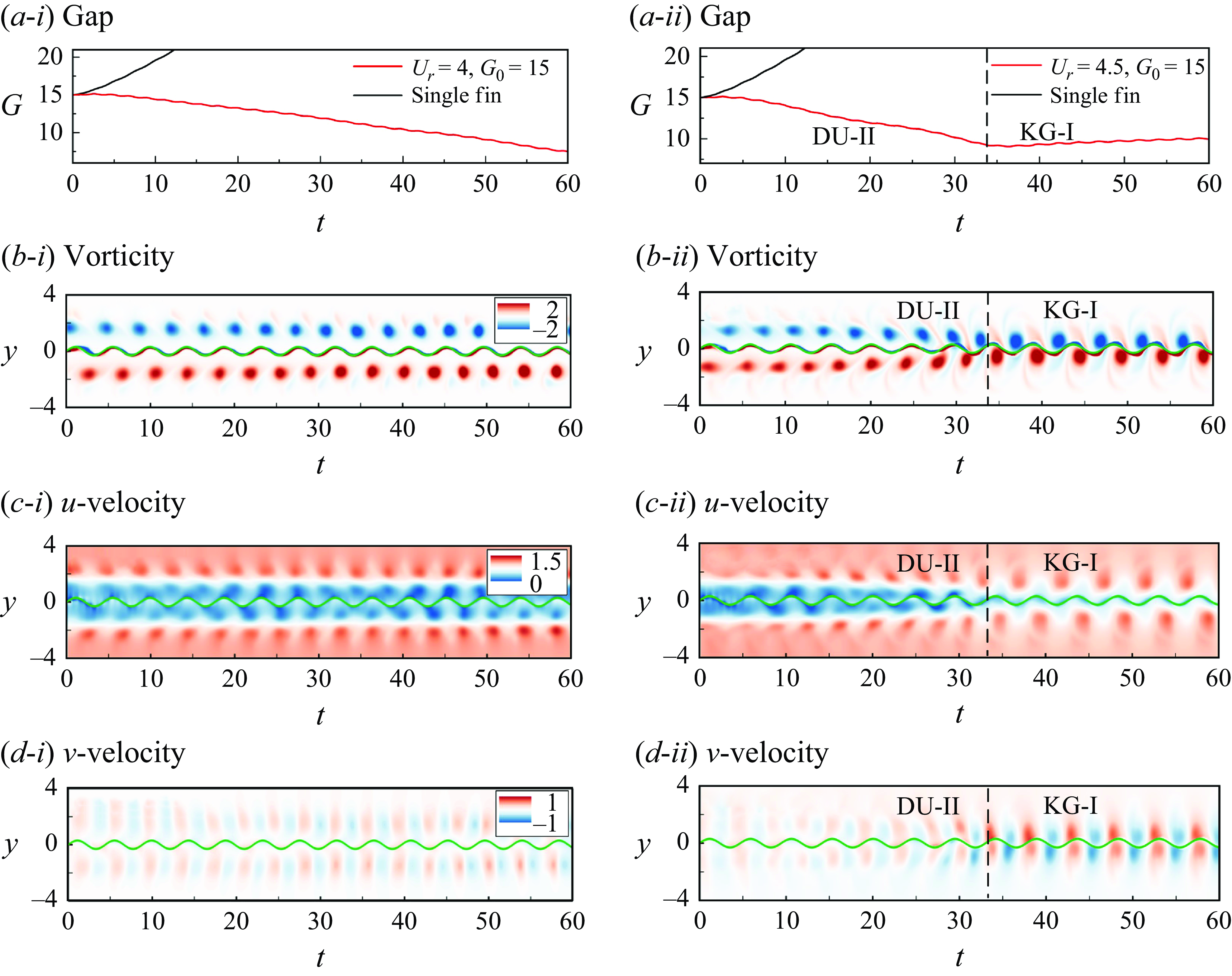
In this subsection, another new swimming behaviour will be introduced, referred to as the drifting upstream II (DU-II) mode. As shown in figure 5(c-iii), the double-row vortex shedding mode might be formed in the wake of a VIV cylinder. We observe that a self-propelled fin in the double-row vortices could drift upstream instead of maintaining a stable position, as seen in KG-I or KG-II modes (figure 6). As the initial gap
 $G_0$
ranges from 3 to 15 at
 $U_r=4.0$
, and from 8 to 15 at
 $U_r=4.5$
, the self-propelled fin consistently swims towards the VIV cylinder, resulting in a decreasing gap
 $G$
. However, it is noteworthy that the swimmer eventually stops locomotion and holds a stable position at approximately
 $G=1.9$
at
 $U_r=4.0$
, and
 $G=10.3$
at
 $U_r=4.5$
, as shown in figure 6(c,d). This behaviour is attributed to the fact that the wake generated by a VIV cylinder does not immediately form the double-row mode. Instead, the vortices are similar to the 2S mode in the near region behind the circular cylinder, then the upstream vortices separate into rows under the action of the moving body (figure 5
c-iii). Consequently, the double-row wake consists of two different vortex shedding modes, leading to two swimming modes of the self-propelled fin – one to drift towards upstream, and the other to hold a stable state near the cylinder. Overall, in the DU-II mode, the fin is capable of gaining significant hydrodynamic advantages.
Time evolutions of the (a) position, (b) vorticity, (c) streamwise velocity and (d) normal velocity along the vertical line, at the leading edge of the self-propelled flexible fin, with
 $G=15$
and
 $U_r=4$
and 4.5.

To investigate the dynamics of DU-II mode, a specific case with
 $U_r=4$
and
 $G=15$
is chosen. The left-hand column of Figure 13 presents the time evolutions of the gap distance, vorticity,and streamwise and normal velocities along the vertical line at the leading edge of the fin, respectively. The results show that the leading edge of the fin consistently flaps between the two-row vortices. Notably, the streamwise velocity in figure 13(c-i) experiences a noticeable reduction between the two rows. Calculating the mean streamwise velocity in both space and time for
 $-0.3\lt y\lt 0.3$
and
 $30\lt t\lt 60$
yields the value
 $0.292$
. Comparing to the free-stream velocity, i.e.
 $U_\infty =1$
, a 71 % reduction is achieved. This significant reduction in
 $u$
leads to a reduction in drag, consequently enhancing the swimming performance of the self-propelled fin. Regarding the normal velocity in figure 13(d-i), it is considerably lower than that in other swimming modes, such as KG-I in figure 9(c) and KG-II in figure 11(c). On one hand, a small normal velocity may not provide sufficient advantages for the required power of the flapping motion on the leading edge. On the other hand, the flapping motion in the DU-II mode is not precisely in phase with the normal velocity. These observations indicate that the self-propelled fin may not benefit from the normal velocity in the VIV wake with a double-row vortex shedding mode. The results also suggest that the primary cause for fast locomotion in the DU-II mode is the reduction in streamwise velocity. Similarly,the right-hand column of figure 13(a-ii–d-ii) shows the time evolutions of the leading-edge data at
 $U_r=4.5$
and
 $G=15$
. The swimming characteristics of the swimmer are identical in both cases before
 $t=30$
, where they both exhibit the DU-II mode. However, after
 $t\approx 30$
, the fin at
 $U_r=4.5$
and
 $G=15$
gradually reaches a stable state with an almost constant gap
 $G$
(see figure 13
a-ii). Simultaneously, the fin manoeuvres between the vortex cores, resembling the KG-I mode. This phenomenon can be attributed to the differences in the double-row wakes generated at
 $U_r=4.0$
and 4.5, as illustrated in figure 5(c-iii). With the increase of
 $U_r$
to 4.5, the transition position between the two vortex shedding modes (separation gap) also changes from 2 to 10. Consequently, we observe a switch in swimming mode from DU-II to KG-I at
 $U_r=4.5$
when
 $G$
reaches 10. This also explains, in figure 6(d), why the self-propelled fin starting at an initial gap
 $G_0\gt 10$
first drifts upstream and then converges to gap
 $G\approx 10$
. Additionally, if the initial gap is lower than
 $G_0=8$
, then the swimmer exhibits the KG-I mode, resulting in several discrete stable positions with a distance equal to the streamwise gap of vortex cores.
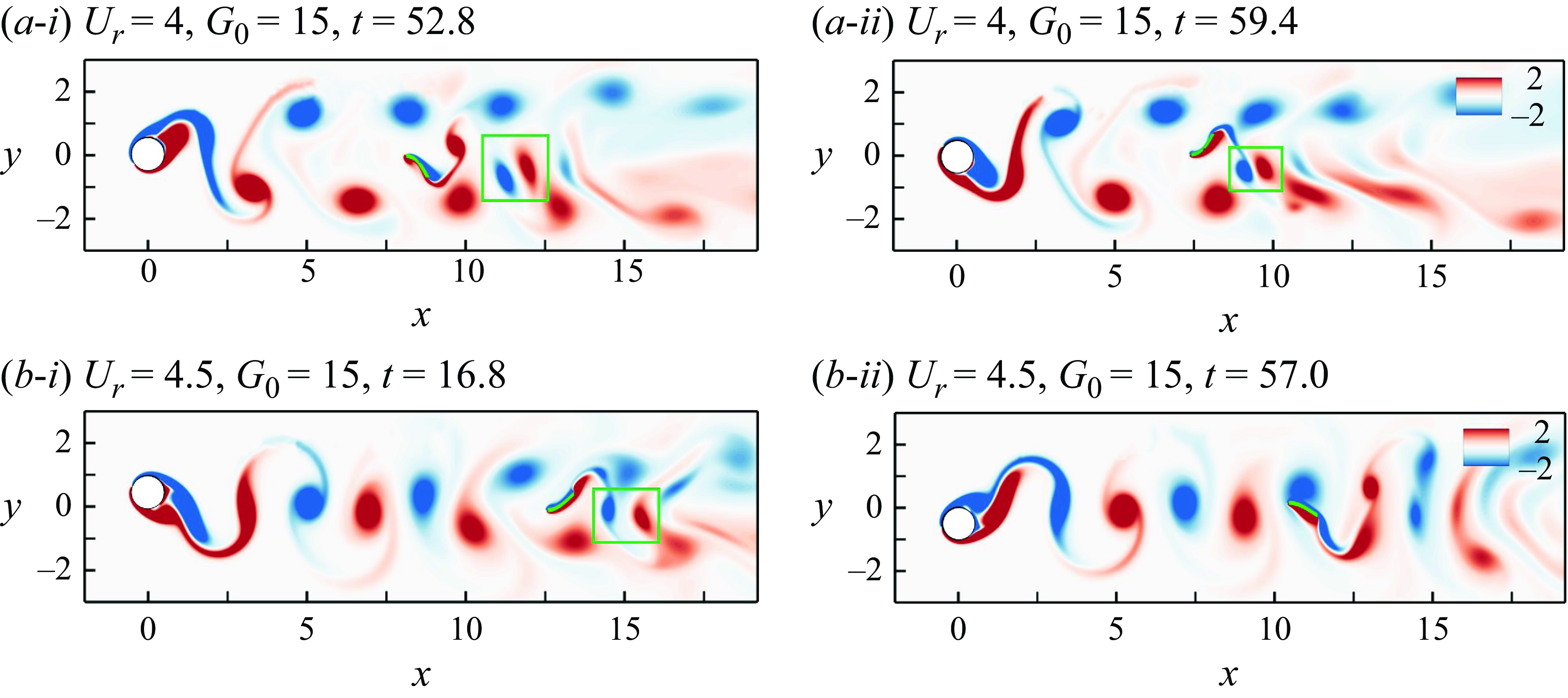
Vorticity contours at different instants. The green square represents the symmetry breaking zone in the wake. More details can be found in supplementary movie 4.

In figure 14, the vorticity contours of the DU-II mode are presented. Notably, the vortex shedding exhibits distinct features compared to other modes. The key difference lies in the formation of a pair of structures by the positive and negative vortices generated at the tail during a flapping cycle, which subsequently shed in the same normal direction. Considering the symmetric nature of the flapping motion on the leading edge, the asymmetric vortex shedding described above indicates a symmetry breaking in the DU-II mode. This symmetry breaking is expected to result in a non-zero force in the streamwise direction, potentially increasing the thrust of the swimmer. The beneficial impact of symmetry breaking on swimming performance has been demonstrated experimentally by Godoy-Diana et al. (Reference Godoy-Diana, Aider and Wesfreid2008, Reference Godoy-Diana, Marais, Aider and Wesfreid2009) using a flapping rigid foil. A numerical study of Alben & Shelley (Reference Alben and Shelley2005) also found that the symmetry breaking leads to forward flapping flight.
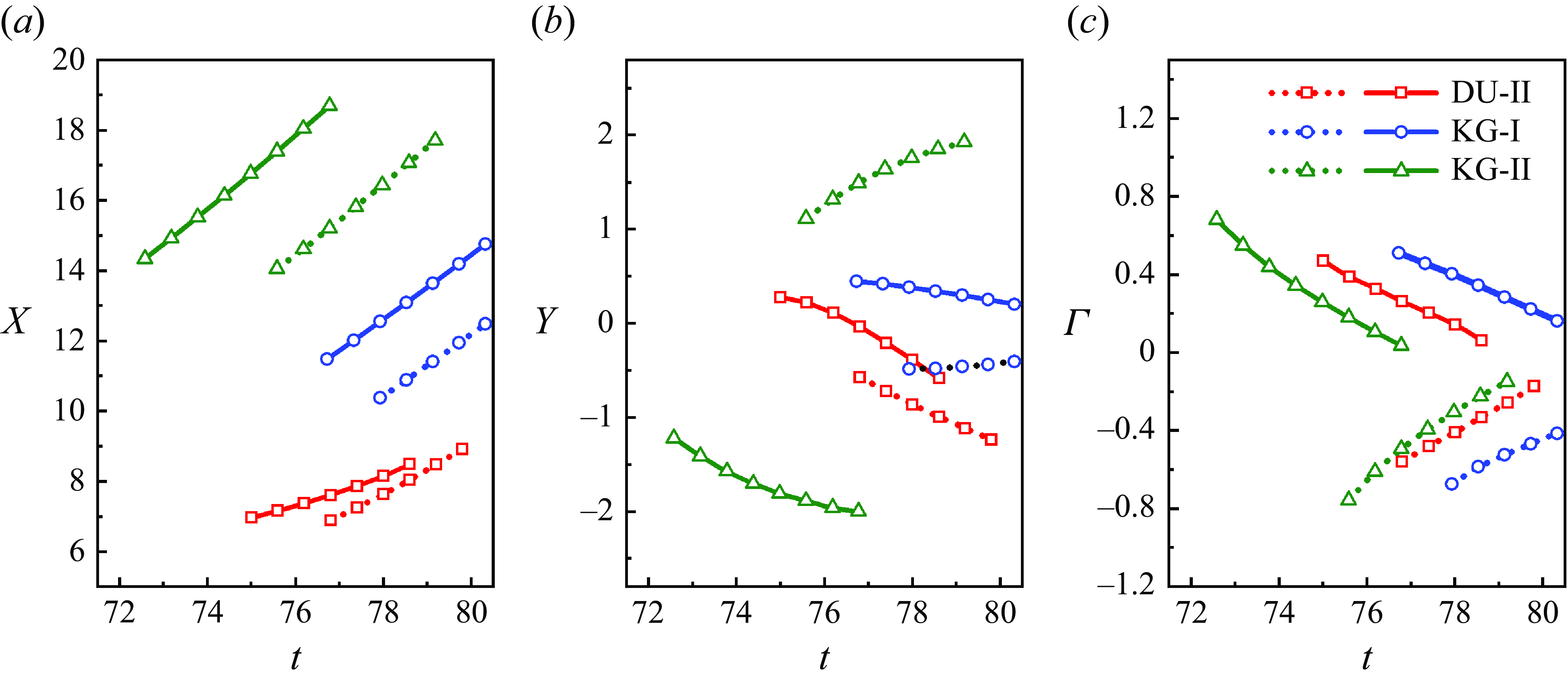
Time histories of the positions and circulations of the vortices: (a) streamwise position, (b) normal position, (c) circulations. Solid and dotted lines denote the positive and negative vortices, respectively.

To conduct a quantitative analysis and to explore the possible cause of the symmetry breaking in the wake, we extract the positions of vortex cores and track their evolution over time. Figure 15(a,b) present the positions of vortices for the case
 $U_r=4.0$
and
 $G=15$
. Additionally, data for
 $U_r=2.0$
and
 $G=7$
, representing the KG-I mode, and
 $U_r=6.5$
and
 $G=12$
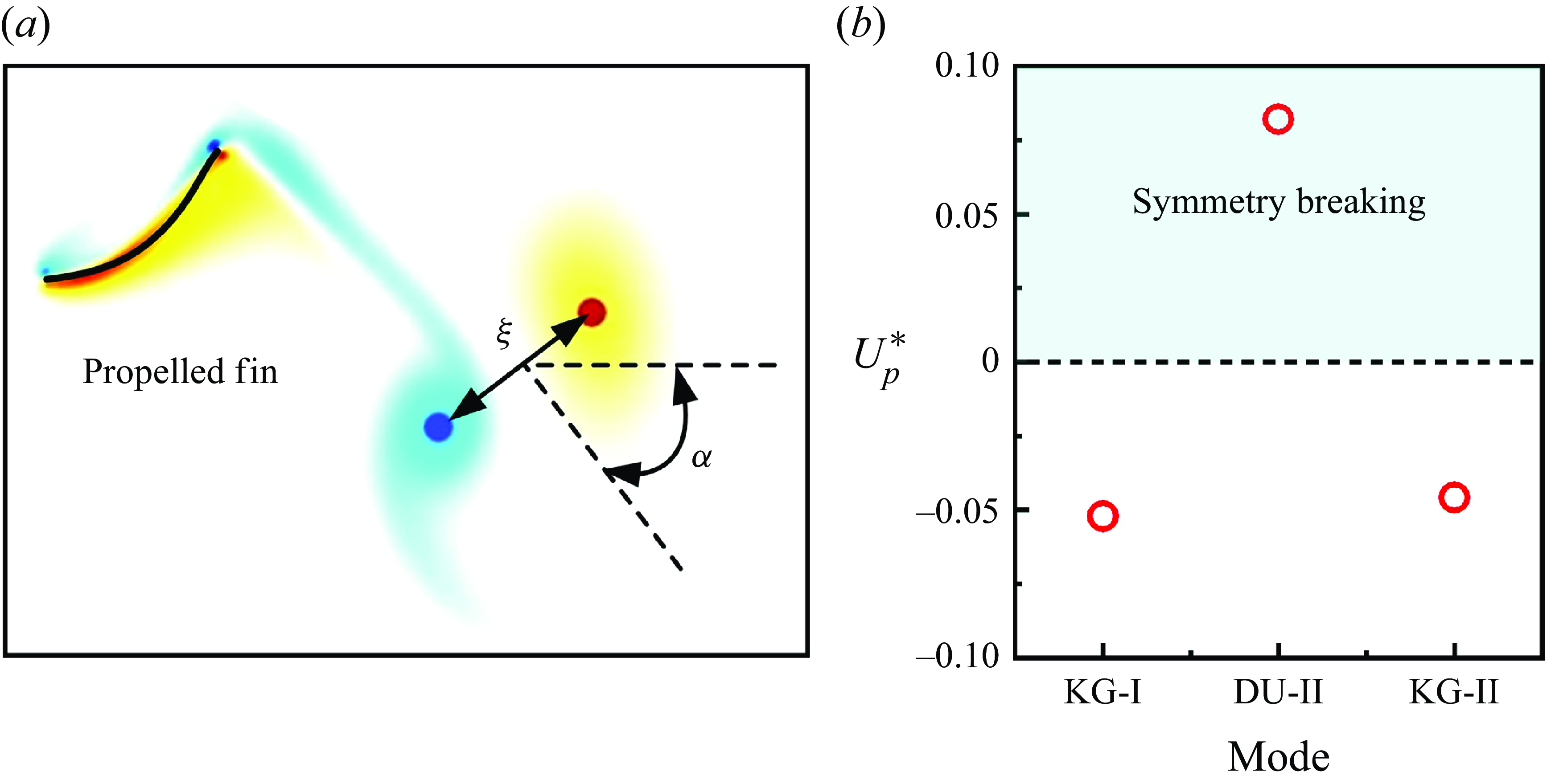
, representing the KG-II mode, are included for comparison. Figure 15(a) illustrates that vortices in the DU-II mode exhibit slower downstream movement compared to other modes, indicating higher momentum transfer resulting from the fin in the wake. This observation suggests a significant alteration of the VIV wake in the DU-II mode compared to the free-stream condition. The increased swimming velocity of the fin in the DU-II mode can be attributed to the increased streamwise momentum transferred to the surrounding fluid. Examining the normal position of the vortices in the KG-I/II modes in figure 15(b) reveals nearly symmetrically opposite distributions, indicating symmetric shedding of vortices. In contrast, calculating the slopes in figure 15(b) yields negative values −0.23 and −0.22 for the positive and negative vortices in the DU-II mode, respectively, providing evidence of asymmetric vortex shedding. Godoy-Diana et al. (Reference Godoy-Diana, Marais, Aider and Wesfreid2009) proposed a dipolar model to explain and estimate the symmetry breaking of a flapping fin. This model compares the phase velocity of the vortex street,
 $U_{phase}$
, with the idealised self-advection velocity of two consecutive counter-rotating vortices in the near wake,
 $U_{d}$
. The dipolar model can be expressed as
 \begin{equation} U_{p}^{*}=(U_{phase}-U_{\infty })\cos \alpha -U_{d}, \end{equation}
where
 $U_{p}^{*}$
is the effective phase velocity to estimate the symmetry breaking, and
 $U_{phase}$
equals the travelling velocity of the vortices in the streamwise direction (i.e. the slope in figure 15
a). A schematic illustrating
 $U_{d}$
is depicted in figure 16(a), with the equation for
 $U_{d}$
expressed as
 \begin{equation} U_{d}=\dfrac {\Gamma }{2\unicode{x03C0} \xi }, \end{equation}
where
 $\xi$
denotes the distance between two consecutive counter-rotating vortices, and
 $\Gamma$
represents the vortex circulation. Following Zhang et al. (Reference Zhang, Sung and Huang2022b
), we adopt 60 % of the maximum vortex intensity as a criterion to define the domain of integration for
 $\Gamma$
. The corresponding results are illustrated in figure 15(c). Additionally, figure 16(b) presents the variations in
 $U_{p}^{*}$
across different swimming modes. It is noteworthy that
 $U_{p}^{*}$
is observed to be positive for the DU-II mode, indicating once again the occurrence of symmetry breaking, which is further attributed to the presence of the two consecutive counter-rotating vortices. On the other hand, the values of KG-I/II are found to be negative. Note that the wake deflection caused by symmetry breaking in the DU-II mode is time-varying. At
 $U_r=4$
and
 $G_0=15$
, the vortex is deflected downwards, while at
 $U_r=4$
and
 $G_0=10$
, the wake curvature is upwards, with the bending angles of both wakes changing slightly over time. Recent studies on flapping foils in uniform flow have also highlighted the time-dependent characteristics of symmetry breaking (Chao et al. Reference Chao, Alam, Ji and Wang2021b
; Zhong & Quinn Reference Zhong and Quinn2024). Zhong & Quinn (Reference Zhong and Quinn2024), through both experiments and simulations, concluded that achieving stable symmetry breaking under flapping is challenging, requiring up to 200 flapping cycles to reach a permanent state. In the present study, the incoming flow is non-uniform, and in the DU-II mode, the rapid swimming of the flexible fin brings it closer to the upstream cylinder, which may further complicate the process of reaching a permanent state.
(a) A schematic of the vortex-induced velocity and the parameters applied in the dioplar model. (b) The effective phase velocity
 $U_p^*$
with respect to the swimming modes, with
 $U_p^*=0$
being the criterion for symmetry breaking.

A schematic illustrating the interactions of the vortices and the leading edge of the DU-II mode is presented in figure 10(c). This diagram sheds light on the reduction of the environmental fluid velocity around the swimmer. The positive vortices on the bottom induce rotation in the surrounding fluid, creating vortex-induced velocity (depicted by the green arrows) in the opposite direction to the free-stream velocity
 $U_\infty$
. At the top, owing to the opposite rotation directions of negative and positive vortex structures, the surrounding fluid experiences vortex-induced velocity in the same direction as at the bottom. Consequently, a low-velocity region is formed. The symmetry breaking of the propulsion, combined with a low environmental fluid velocity, allows the fin to gain significant hydrodynamic advantages in the DU-II mode.
3.2.5. Large oscillation (LO) mode
When the self-propelled fin operates at a reduced velocity ranging from
 $U_r=3$
(resulting in the KG-I mode) to
 $U_r=4$
(resulting in the DU-II mode), the large oscillation (LO) swimming mode is observed. As illustrated in figure 6(e), the LO mode is characterised by the fin maintaining an almost stable position but with large oscillations in the dynamic gap
 $G$
. This implies that the swimmer in LO mode moves alternately upstream and downstream due to the presence of a quasi-chaotic wake formed by a VIV cylinder. Referring to figure 5(c-ii), the quasi-chaotic wake is essentially in transition from the 2S mode in figure 5(c-i) to the double-row mode in figure 5(c-iii), indicating a switch between vortex shedding modes. By computing the vortex shedding frequency at
 $U_r=3.5$
, one can find the presence of much noise in the frequency spectrum. Consequently, the LO mode exhibits a DU-II-like behaviour with forward motion, as well as adjustments and backward motions. Additionally, a more detailed depiction of the LO mode is presented in supplementary movie 5.
3.3. Energy transfer of the system
3.3.1. Energy transfer regarding the locomotion of the fin
In this subsubsection, we focus on the energy transfer in the FSI of the system. For a self-propelled system, the input energy during a flapping period can be modelled mainly in the following two ways, depending on the use of the total force with the whole deformation of the fin or only the imposed force and motion at the leading edge (Zhu et al. Reference Zhu, He and Zhang2014; Park et al. Reference Park, Kim and Sung2016). At present, we define the input power as
 \begin{equation} P_{i}=\dfrac {1}{T}\int _{0}^{T}F_y(1,t)\,\dfrac {\partial Y(1,t)}{\partial t}\,{\rm d}t, \end{equation}
where ‘1’ represents the first Lagrange node (the leading edge) of the flexible fin. Then some explanations about the computation of power coefficient
 $C_{pf}$
(or efficiency) should be given. Typically, the ratio of applied power to input power is useful to quantify propulsive efficiency. However, one can find that the thrust and drag of a self-propelled system should be balanced. Thus the resultant force in the streamwise direction is near zero, leading to difficulties in separating the thrust and therefore in obtaining the useful power. Some experimental studies additionally measured the thrust force by setting the flapping foil held in a fixed position. The previous numerical studies applied kinetic energy in the fin forward motion with the energy passed to the fluid by the fin to estimate the power coefficient (Zhu et al. Reference Zhu, He and Zhang2014; Park & Sung Reference Park and Sung2018), i.e.
 $C_{pf}=\rho _s U_{avg}^2/(2TP_{i,avg})$
. Here,
 $T$
is the flapping period of one oscillation, defined as
 $T=1/St$
. The parameters
 $U_{avg}$
and
 $P_{avg}$
are the mean quantities obtained by
 \begin{equation} U_{avg}=\dfrac {1}{T}\int _{t}^{t+T}U_c\,{\rm d}t, \quad P_{avg}=\dfrac {1}{T}\int _{t}^{t+T}P_i\, {\rm d}t, \end{equation}
for which the cruising speed
 $U_c$
is defined in (2.12). Note that the above
 $U_{avg}$
adopted in literature (Zhu et al. Reference Zhu, He and Zhang2014; Park & Sung Reference Park and Sung2018) is for a self-propelled fin in the still fluid instead of the present flow with free-stream velocity. For this reason, both the swimming velocity and the free-stream velocity
 $U_{\infty }$
should be taken into account. Although the fin in the VIV wake may encounter different flow environment and velocity, we apply
 $U_{\infty }$
for all cases for consistency. Therefore, the power coefficient is computed by
 \begin{equation} C_{pf}=\dfrac {\rho _s \left(U_{avg}+U_{\infty }\right)^2}{2TP_{i,avg}}. \end{equation}
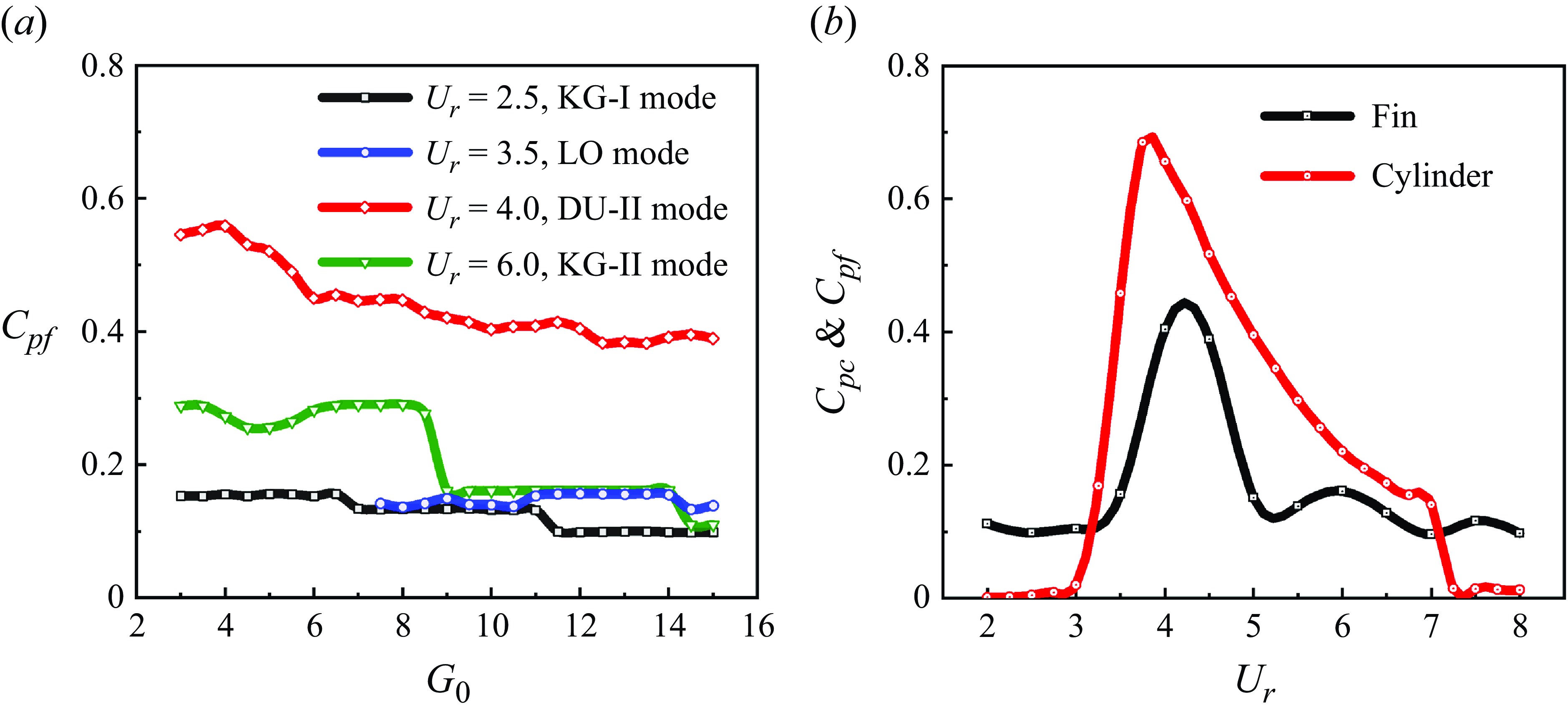
(a) Variations of the power coefficient of the present self-propelled fin
 $C_{pf}$
with respect to the initial gap
 $G_0$
for different swimming modes. (b) Comparison of the power coefficient of the upstream VIV cylinder and the downstream propelled fin.

Figure 17(a) shows the power coefficient with respect to the gap with different reduced velocities that includes all the swimming modes presented in § 3.2. Note that since the fin in the DU-I mode drifts by the suction zone with negative flow velocities compared to
 $U_{\infty }$
, it might cause a negative input power as well. For a reasonable comparison, the data for the DU-I mode are not shown in figure 17. In general, one can find that the self-propelled fin has the maximum power coefficient
 $C_{pf}$
for the DU-II mode, where the swimmer can drift upstream continuously. In addition, the fin in the KG-II mode is able to apply the power more efficient than that in the KG-I mode, although the above modes exhibit similar locomotions with stable states. With the increased gap
 $G_0$
, the power coefficient
 $C_{pf}$
experiences a reduction, which can be understood as the vortices in the VIV wake become weak away from the bluff body, and the available power decreases. For the KG-I and KG-II modes, the fin converges to several stable positions as shown in figure 6, and therefore the applied power should be similar among the identical solutions, leading to plateaus in figure 17(a).
Leaving the initial gap
 $G_0$
unchanged, a relationship between the power coefficient
 $C_{pf}$
with the reduced velocity can be obtained. Considering the pattern classification in figure 6(a),
 $G_{0}=12$
is selected to include all the swimming modes without the DU-I mode. Figure 17(b) shows that
 $C_{pf}$
increases and then decreases with
 $U_r$
. In addition, it is interesting to see if there are similarities of the energy transfer between the self-propelled fin and the upstream oscillating cylinder. For this, the available power of the fluid flow that the VIV cylinder can use is estimated to be
 $P_f=0.5\rho _fU^3D$
, based on the Bernoulli theory. Typically, the applied power of such a VIV system is defined based on the damping term (Han et al. Reference Han, Huang, Qin, Wang and Zhao2023a
); however, zero damping ratio is used at present. Here, we define
 $C_{pc}$
as the ratio of kinetic energy to
 $P_f$
, i.e.
 \begin{equation} C_{pc}=\dfrac {\int _{T}^{nT}M \dot {Y_c}^2\, {\rm d}T}{nT\rho _fU^3D}=\dfrac {\int _{t}^{nt}0.25\unicode{x03C0} m_s^* \dot {y}^2\, {\rm d}t}{t}. \end{equation}
The results for the above
 $C_{pc}$
with the reduced velocity
 $U_r$
are also plotted in figure 17(b) for comparison. Interestingly, one can find that the energy coefficient
 $C_{pc}$
of the upstream VIV cylinder shares a similar variation trend with
 $C_{pf}$
. This suggests that if more power is transferred as the kinetic energy of the VIV, then it creates the conditions for a swimmer to gain more hydrodynamic benefits from its wake.
3.3.2. Energy transfer regarding the passive deformation of the fin
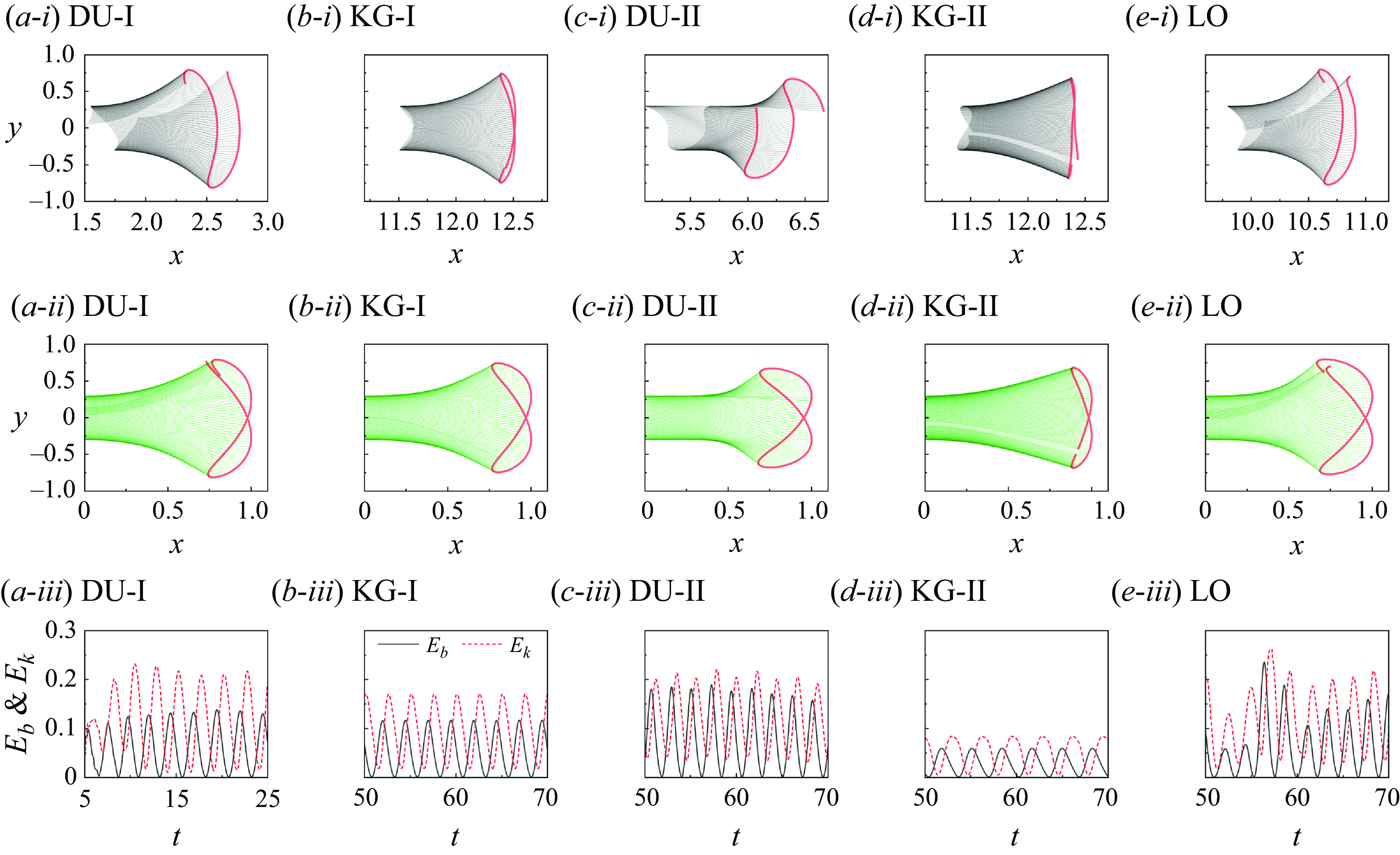
The superimposed configurations of the flexible fins cross different swimming modes in the Cartesian coordinate system (top row) and relative to their leading edge positions (middle row). The bottom row shows time histories of the elastic energy (
 $E_b$
) and kinetic energy (
 $E_k$
) under different swimming modes.

The top row of figure 18 illustrates the instantaneous shapes and passive deformations of the self-propelled flexible fin during one flapping cycle across different locomotion modes. The occurrence of the DU-I mode requires the fin to be positioned near the upstream cylinder. For this mode, the parameters are set to
 $ U_r = 2$
and
 $ G_0 = 3.5$
, as shown in figure 18(a-i). For the other modes, the initial release position is set at
 $ G_0 = 10$
, with corresponding values
 $ U_r = 2$
for the KG-I mode (figure 18
b-i),
 $ U_r = 3.5$
for the LO mode (figure 18
e-i),
 $ U_r = 4$
for the DU-II mode (figure 18
c-i), and
 $ U_r = 6.5$
for the KG-II mode (figure 18
d-i). As shown in the figures, the bending deformations of the flexible fin in both the KG-I and KG-II modes are quite similar, with both modes exhibiting localised flapping. However, in the KG-I mode, the fin experiences stronger interactions with the unsteady vortices in the incoming flow, leading to more pronounced passive bending and deformation. This is because in the KG-I mode, the vertical distribution of positive and negative vortices is broader, requiring the flexible fin to move around the vortex cores to gain hydrodynamic benefits, which necessitates larger deformations. In terms of DU-I, DU-II and LO modes, the self-propelled flexible fin exhibits significant displacement in the streamwise direction. Notably, the flapping in the DU-II mode shows asymmetry. In addition to the Cartesian-coordinate-based superimposed configurations of flapping, we present normalised instantaneous shapes in the middle row of figure 18. Interestingly, the results indicate that the flapping in the DU-II mode here maintains good symmetry, as in figure 18(b-ii).
The deformation of the self-propelled flexible fin is passive, driven by the combined effects of vortex–structure interaction, and is accompanied by energy transfer between elastic energy (
 $E_b$
) and kinetic energy (
 $E_k$
). The bottom row of figure 18 presents the time histories of
 $E_b$
and
 $E_k$
, where the definitions of these energies are
 \begin{equation} E_b=\int _{2}^{L} 0.5\gamma \left ( \frac {\partial ^2 \mathbf{X}}{\partial s^2} \right )^2 {\rm d}s, \end{equation}
 \begin{equation} E_k= \int _{2}^{L} \frac {1}{2} \rho \textbf {u}_{ib}^2\, {\rm d}s, \end{equation}
where
 $ \textbf {u}_{ib}$
represents the velocity at the Lagrangian nodes of the fin. Here,
 $ E_b$
denotes the work done by the restoring force to deform the flexible fin, while
 $ E_k$
represents the work done by the fluid (including the vortices) to move the fin. It is evident from the bottom row of figure 18 that
 $ E_b$
and
 $ E_k$
alternate in rising and falling. The alternating variations of these two energies reflect the process by which the flexible fin deforms under fluid forces and generates thrust. As shown in the bottom row of figure 18, at certain instances,
 $ E_b$
approaches zero, indicating that the flexible fin is nearly straight. At these points, the restoring force has minimal effect, and the hydrodynamic forces dominate. As passive deformation increases, the flexible fin enters a state of energy storage, with
 $ E_b$
becoming more significant while
 $ E_k$
decreases. During the subsequent half-cycle, the energy stored in the deformation of the fin is released and converted into
 $ E_k$
for locomotion, after which the fin returns to its straight position. It is important to note that a phase difference exists between the energy transfer of
 $ E_b$
and
 $ E_k$
, leading to their local maxima and minima not occurring simultaneously. Furthermore, when comparing different swimming modes, it is observed that the energy transfer in the KG-I and KG-II modes is more regular, as these modes exhibit more stable movements and flapping states, as illustrated in figure 6. Although the energy transfer in both the KG-I and KG-II modes is similar, the energy levels in the KG-II mode are notably smaller than those in the KG-I mode. This difference can be attributed to the lower upstream vortex shedding frequency (and consequently, the lower flapping frequency of the leading edge) – see figure 5(b), with
 $ St = 0.152$
at
 $ U_r = 2$
for the KG-II mode, and
 $ St = 0.201$
at
 $ U_r = 2$
for the KG-I mode – the smaller required deformations to navigate the vortex cores (see the middle row of figure 18), and the stronger upstream VIV vortex intensities (see figure 12
b), in the KG-II mode.
4. Discussion
4.1 Flapping frequency of the flexible fin
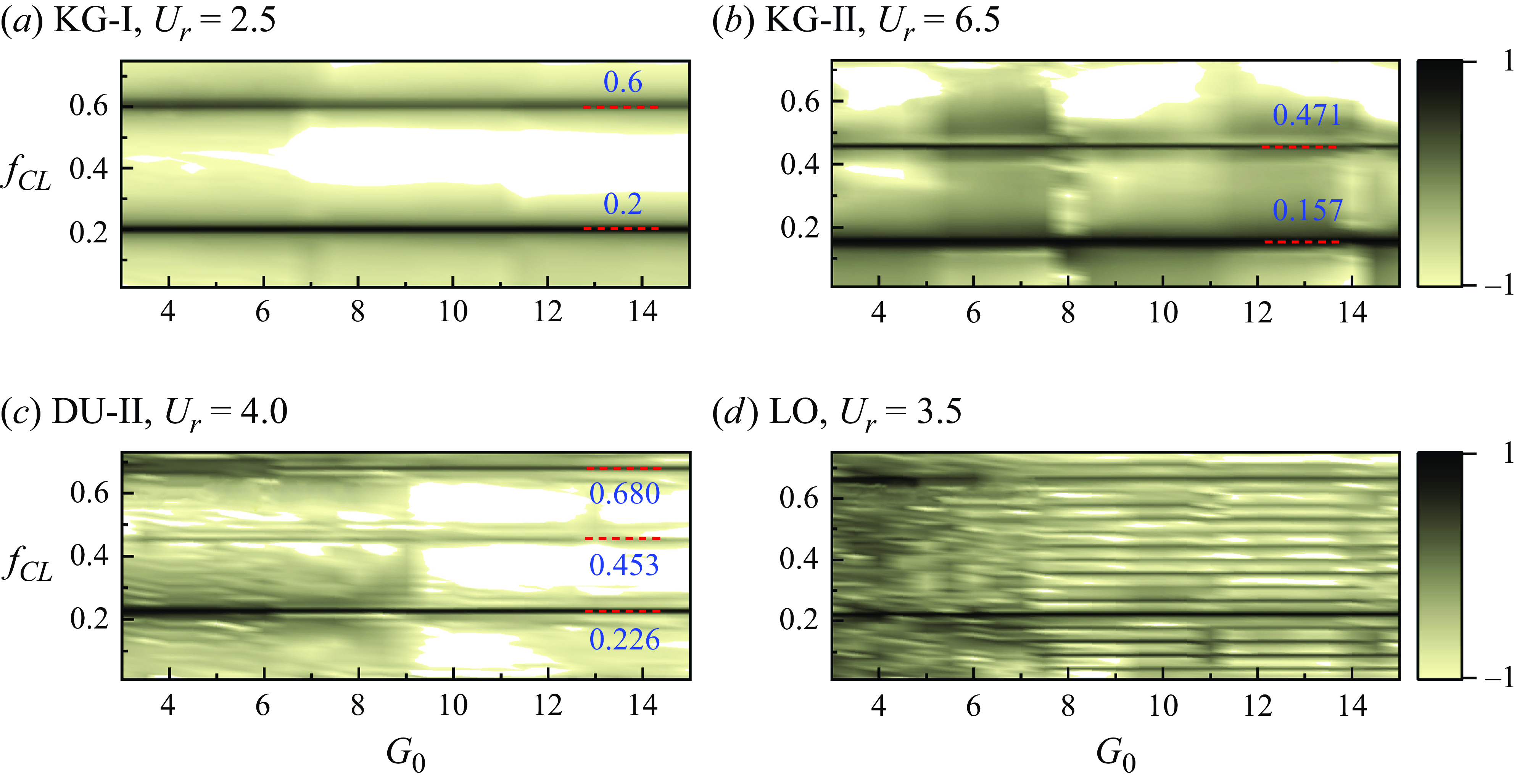
Computing the frequency spectrum of the fin’s lift allows us to analyse the vortex shedding frequency in the wake. Figure 19 presents the normalised logarithmic-scale power spectrum density contours of the frequency response of the lift with various initial gaps
 $G_0$
and reduced velocities
 $U_r$
. The construction method for this figure can be found in Zhao et al. (Reference Zhao, Leontini, Lo Jacono and Sheridan2014) and Han et al. (Reference Han, de Langre, Thompson, Hourigan and Zhao2023b
). Essentially, the spectra corresponding to the KG-I and KG-II modes, shown in figure 19(a,b), respectively, exhibit relative cleanliness with only two significant peaks. In the KG-I mode (figure 19
a), the main peaks are observed at 0.2 and 0.6, while in the KG-II mode (figure 19
b), they are at 0.157 and 0.471. Notably, 0.2 and 0.157 correspond to the flapping frequency of the leading edge, i.e. the VIV vortex shedding frequency
 $St$
in figure 5(b). Furthermore, a 1 : 3 synchronization is evident in the relationship between these main peaks, indicating the fin’s experience of high-order synchronization in the KG-I and KG-II modes. For the DU-II mode (figure 19
c), the frequency spectrum not only exhibits two peaks with 1 : 3 synchronization, but also shows a relatively small peak at approximately 0.453, precisely twice the oscillation frequency of the leading edge. The presence of integral multiple peaks suggests a super-harmonic-resonance phenomenon occurring between the fin and the VIV wake. Importantly, the occurrence of an even number times of the primary frequency leads to an asymmetric vortex shedding wake, as observed in figure 13. In the context of a VIV cylinder, the previous experiments of Morse & Williamson (Reference Morse and Williamson2009) demonstrated that an asymmetric wake pattern P+S could accompany the second-order harmonic exhibiting a peak frequency, whereas 1 : 3 synchronization would result in the symmetric 2P mode. These earlier findings are consistent with the present results. In figure 19(d), where the fin exhibits the LO mode in a complex VIV wake, there is considerable noise in the spectrum compared to figure 19(a,b), where the fin maintains a stable position with stable wakes.
Logarithmic-scale power spectrum density contours of normalised frequency response of the lift
 $f_{CL}$
as a function of initial gap
 $G_0$
for different swimming modes. The main peaks are marked by the red dashed lines.

4.2 The VIV responses of the upstream cylinder
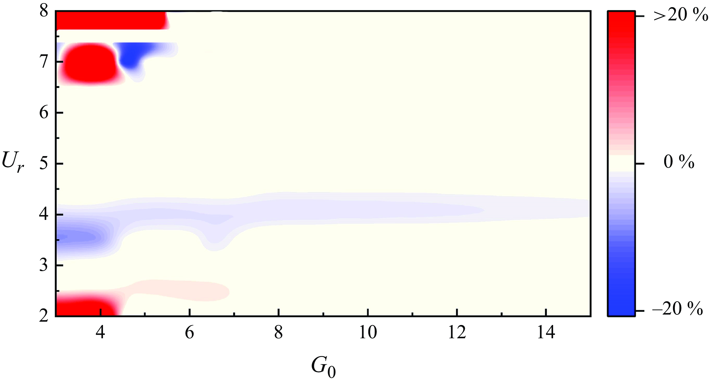
To determine how the swimming behaviour of a self-propelled fin can influence the VIV amplitude of an upstream cylinder, figure 20 shows a contour map of the amplitude variation ratio of the upstream VIV cylinder as a function of the reduced velocity
 $U_r$
and the fin–cylinder gap
 $G_0$
. The baseline amplitude
 $A_c$
of a bare cylinder in figure 5(a) was used to calculate the percentage change in upstream amplitude when a self-propelled fin is positioned downstream. Comparing figure 20 and the swimming modes in figure 6(a) shows that only when the fin is in the drifting upstream modes (DU-I/II) does it significantly affect the amplitude of the upstream cylinder. In other swimming modes, the stable swimming position of the fin is sufficiently distant from the cylinder, thus failing to effectively influence the near-wake vortex shedding and pressure variations, consequently having negligible impact on the VIV responses. Moreover, in the DU-I mode, it is noticed that the downstream fin stimulates the cylinder’s amplitude, while it suppresses the VIV amplitude in the DU-II mode. From figures 5(a) and 6(b), it is evident that the DU-II mode corresponds to large-amplitude VIV responses of the upstream cylinder, whereas the DU-I mode corresponds to small-amplitude VIV responses. As a result, it can be inferred that when a self-propelled fin approaches an upstream VIV cylinder, it suppresses the maximum amplitude within the lock-in range while stimulating VIV oscillations outside the lock-in region.
Contour map of the amplitude variation ratio of the upstream cylinder, as a function of reduced velocity
 $U_r$
and initial gap
 $G_0$
.

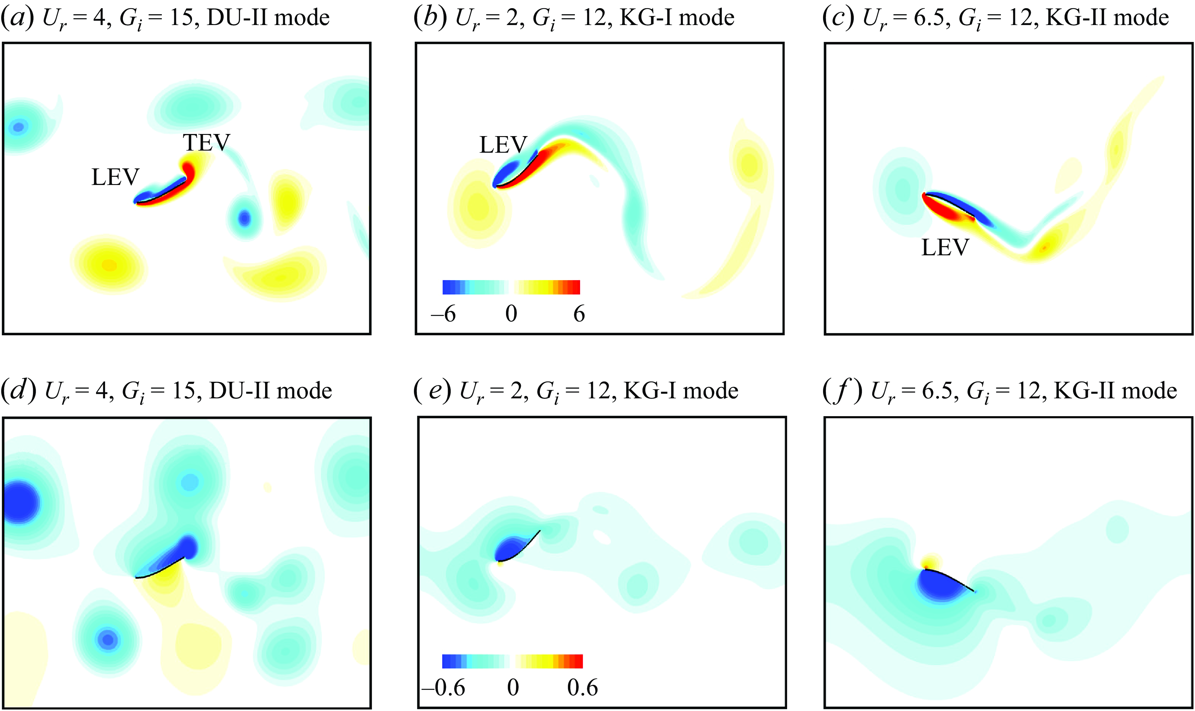
(a–c) Vorticity and (d–f) pressure contours in different swimming modes, representing the leading- and trailing-edge vortices (LEV and TEV).

4.3 Edge vortices
The leading- and trailing-edge vortices are widely accepted mechanisms that explain efficient locomotion in biological systems (Bomphrey et al. Reference Bomphrey, Nakata, Phillips and Walker2017; Zhang et al. Reference Zhang, Zhang and Huang2022a , Reference Zhang, Sung and Huangb ). Due to the attachment effect of the leading- or trailing-edge vortices, a low-pressure zone may form on one side of the oscillating propulsive structure (i.e. the fin), thereby enhancing propulsion capability or saving energy. Figure 21 illustrates the vorticity and pressure contours around the present self-propelled fin in three swimming modes (DU-II, KG-I and KG-II). To facilitate a better comparison, we selected similar flapping postures across different swimming modes. The results indicate the presence of leading-edge vortex mechanisms in all three modes, with both leading- and trailing-edge vortex mechanisms observed in the DU-II mode. This suggests that the efficient propulsion in the DU-II mode may benefit from the simultaneous existence of trailing-edge vortices.
4.4 Initial condition effects
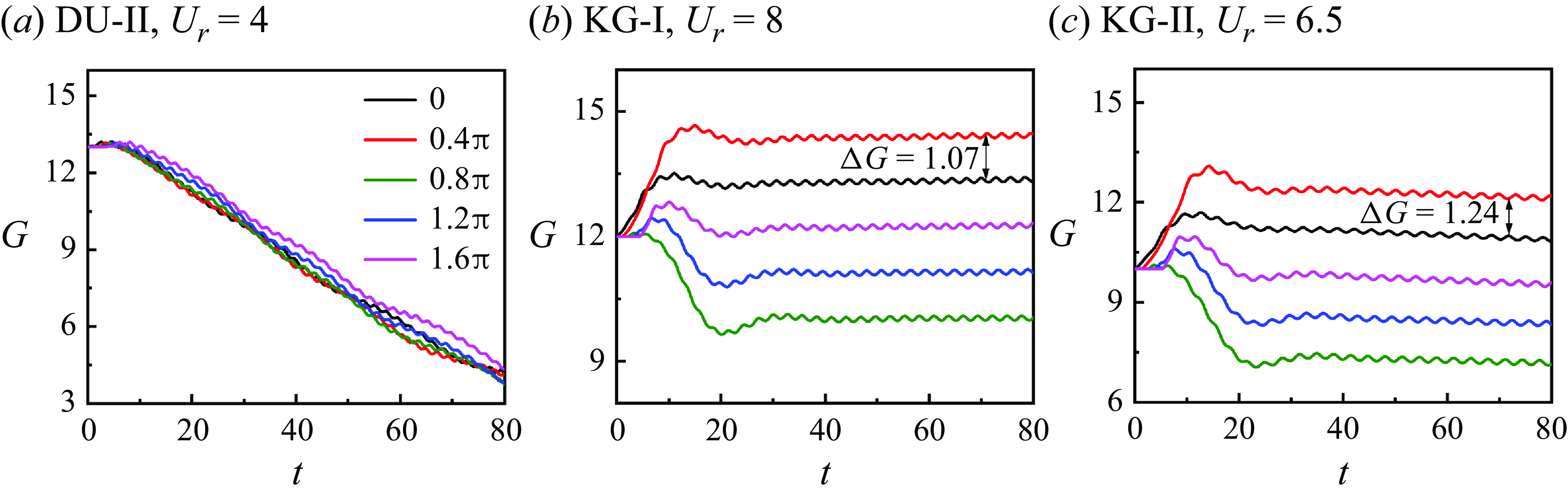
The solution, specifically the final equilibrium gap
 $G$
in the current system, may be influenced by the initial phase difference between the fin’s heaving motion and the unsteady vortices. Defining the initial phase of the tested cases in figure 6 as
 $0$
, figure 22 illustrates the time histories of the dynamic position of the fin’s leading edge for various initial phases ranging from
 $0$
to
 $2\unicode{x03C0}$
. In general, the fin in the DU-II mode appears to exhibit minimal sensitivity to the initial phase, which could offer a potential design advantage for applications. However, the results show phase-dependent variations in the KG-I and KG-II modes. This sensitivity arises from the fact that in the KG modes, the fin needs to either move around or cross through the vortex cores to save energy, necessitating synchronization with the vortex phase. Additionally, as the phase changes from 0 to
 $0.4\unicode{x03C0}$
, the corresponding final equilibrium gap
 $G$
reaches values 13.32 and 14.39 in the KG-I mode, and 11.01 and 12.25 in the KG-II mode. Notably, the differences between the two stable values (
 $\Delta G = 1.07$
and 1.24) approximate the gap between two adjacent positive/negative vortices generated from the upstream VIV wake times
 $0.4\unicode{x03C0} /2\unicode{x03C0}$
, at
 $U_r = 8$
and
 $U_r = 6.5$
, respectively. The influence of initial conditions on the final swimming behaviour is a complex issue, with the system being sensitive not only to phase differences but also to other initial parameters. In a separate study by the authors (Han et al. Reference Han, Zhang, Zhang and Huang2024), extensive parametric tests were conducted to investigate the effects of initial conditions, both for a flexible fin propelled by the wake of an upstream circular cylinder and for fish schooling behaviour. Moreover, two types of initial flow fields were considered: fully developed fluid flow (which better reflects natural environments), and quiescent flow fields (commonly applied in numerical studies). Han et al. (Reference Han, Zhang, Zhang and Huang2024) provides additional insights and a more detailed discussion of the effects of initial conditions.
Time histories of the dynamic gap
 $G$
between the VIV cylinder and the fin’s leading edge with different initial release phase angles and different reduced velocities: (a)
 $U_r=4$
, (b)
 $U_r=8$
and (c)
 $U_r=6.5$
.

4.5 Dimensionality effects
While the use of a two-dimensional (2-D) flexible filament or plate to represent a three-dimensional (3-D) fin or fish body, as well as the 3-D flow, especially at low Reynolds numbers, is a well-established approach validated by 3-D simulations and experiments (Zhu et al. Reference Zhu, He and Zhang2014; Gao & Triantafyllou Reference Gao and Triantafyllou2018; Lau et al. Reference Lau, Huang and Xu2018a , Reference Lau, Zhang, Jia, Huang and Xub ; Park & Sung Reference Park and Sung2018; Peng et al. Reference Peng, Huang and Lu2018), the present study simplifies the complexities of real-world 3-D flows. We conducted an extensive parametric study to identify distinct swimming modes and explore their characteristics. While this simplification allows us to focus on fundamental mechanisms, we acknowledge that 3-D effects, such as spanwise flow structures, may influence the hydrodynamic behaviour of the self-propelled fin and the VIV of the cylinder. Nonetheless, the results presented here still offer valuable insights into 3-D scenarios, for several reasons. First, the Reynolds number in this study is set at 200. Although flow over a fixed circular cylinder at this Reynolds number lies within the 2-D–3-D transition range (Jiang et al. Reference Jiang, Cheng, Draper, An and Tong2016), the flow effectively becomes more 2-D when the cylinder undergoes oscillations. This is due to the increase in vortex shedding correlation length during oscillation (Bearman Reference Bearman1984; Al-Jamal & Dalton Reference Al-Jamal and Dalton2004). Second, Zurman-Nasution et al. (Reference Zurman-Nasution, Ganapathisubramani and Weymouth2020) demonstrated that force statistics are nearly identical in both 2-D and 3-D simulations across a wide range of amplitude-based Strouhal numbers for propulsive flapping foils. Despite strong separation and 3-D features observed in flow over a stationary foil, data obtained from 2-D soap film tunnels and 3-D high-aspect-ratio foil experiments for propelled flapping models align well with 2-D simulations (Schnipper et al. Reference Schnipper, Andersen and Bohr2009; Andersen et al. Reference Andersen, Bohr, Schnipper and Walther2016; Moriche et al. Reference Moriche, Flores and García-Villalba2016; Muscutt et al. Reference Muscutt, Weymouth and Ganapathisubramani2017). Furthermore, as highlighted by Maertens et al. (Reference Maertens, Gao and Triantafyllou2017) and Gao & Triantafyllou (Reference Gao and Triantafyllou2018), the fundamental conclusions drawn from two-dimensional simulations generally translate well to 3-D flows and even to real fish swimming. Third, to the best of the authors’ knowledge, while the interactions between a self-propelled fin and complex VIV wakes have not been tested experimentally, the behaviour of a fin in the wake of a fixed cylinder has been studied extensively via experiments (Liao et al. Reference Liao, Beal, Lauder and Triantafyllou2003; Liao Reference Liao2007). Currently, when the upstream VIV cylinder oscillates with a small amplitude, its wake is identical to that of a fixed cylinder. Our findings, particularly for the KG-I mode (as shown in figure 9), where the fin moves around the vortices to achieve energy savings, are consistent with real fish swimming in 3-D flows. Therefore, the swimming modes observed in VIV wakes are expected to be applicable to 3-D flows. Further studies employing 3-D simulations or experimental investigations are needed to fully capture the complexities of these interactions.
4.6 Reynolds number effects
The Reynolds number distribution for biological swimming propulsion spans a wide range (Chao et al. Reference Chao, Alam and Ji2021a
). Although there are many swimming organisms that function at Reynolds numbers below
 $10^3$
, larger swimmers tend to operate at higher Reynolds numbers. The authors have previously conducted a series of studies on the effects of Reynolds number on biological propulsion. These studies include investigations of tuna swimming at
 $Re = 500$
,
 $1000$
and
 $1500$
(Zhang et al. Reference Zhang, Sung and Huang2020), batoid fish at
 $Re = 1500$
,
 $15\,000$
and
 $150\,000$
(Zhang et al. Reference Zhang, Wang and Gursul2022c
; Zhang & Huang Reference Zhang and Huang2023), and flapping aerofoils across a wide range of Reynolds numbers (Zhang et al. Reference Zhang, Pan, Chao and Zhang2018). The results indicate that the vortex structures and key mechanisms in the wake, at low Reynolds numbers (
 $10^2{-}10^3$
), are qualitatively consistent with those observed at higher Reynolds numbers (
 $10^4{-}10^5$
). Increasing the Reynolds number does not significantly alter the force trends on the fish or the overall topology of the vortex structures. In terms of the present system, figure 23(a) presents the VIV responses of a single circular cylinder at
 $Re = 500$
, including variations in amplitude and frequency. The vibrations exhibit a lock-in region, with different vortex shedding modes. Figure 23(b) shows the characteristics of the position of a self-propelled fin placed in the VIV wakes at
 $Re = 500$
. By comparing the results at
 $Re = 500$
and
 $Re = 200$
(figure 6), we observe consistent conclusions. At
 $Re = 500$
, the downstream flexible fin continues to benefit from hydrodynamic forces and exhibits stable FSI modes, corresponding to the KG-I/KG-II modes, where the fin moves around and crosses through the vortices. Other modes, corresponding to the DU-I and DU-II modes, are also observed, with the fin swimming toward the upstream cylinder. While
 $Re = 500$
still falls within the low Reynolds number regime, we can extrapolate the following for higher Reynolds numbers. For vortex shedding from a single cylinder, wake patterns such as 2S and P+S (DRM mode) observed at low Reynolds numbers are also present at
 $Re = 10^3{-}10^4$
(Williamson & Govardhan Reference Williamson and Govardhan2004), albeit with more fragmented and unstable vortices. The qualitative features of these vortex structures remain consistent, suggesting that the swimming behaviour of flexible fins at higher Reynolds numbers could exhibit similarities to those observed at lower Reynolds numbers.
(a) Amplitude
 $ A_c$
and vortex shedding frequency
 $ S_t$
of VIV of a bare circular cylinder at
 $ Re = 500$
. (b) Time histories of the dynamic gap
 $ G$
between the VIV cylinder and the fin’s leading edge at
 $ Re = 500$
, with
 $ U_r = 2$
and
 $ G_0 = 3.5$
(marked as DU-I),
 $ U_r = 2$
and
 $ G_0 = 10$
(marked as KG-I),
 $ U_r = 4$
and
 $ G_0 = 10$
(marked as DU-II), and
 $ U_r = 5.5$
and
 $ G_0 = 10$
(marked as KG-II). The plots in (b) show the vorticity contours for different swimming modes.

5. Conclusions
This paper presents an investigation of fish swimming behind a vortex-induced vibration (VIV) cylinder, addressing a scenario that is both common and of importance in the field (Eldredge & Pisani Reference Eldredge and Pisani2008). The study aims to answer the questions regarding whether a self-propelled fin can achieve hydrodynamic advantages in a VIV wake, and how the fin behaves when interacting with unsteady vortices. Employing a combination of the immersed boundary method and a flexible filament model, the work explores a wide range of parameters, including reduced velocity (
 $U_r$
), gap position (
 $G_0$
) and initial phase (
 $\phi$
). The findings yield several noteworthy results, which are summarised below.
The data of the
 $U_r$
–
 $G_0$
map reveal the existence of five distinct swimming modes: drifting upstream I (DU-I) mode, Karman gait I (KG-I) mode, large oscillation (LO) mode, Karman gait II (KG-II) mode, and drifting upstream II (DU-II) mode. The behaviour of the fin in the DU-I mode closely resembles observations made in cases involving a stationary cylinder (Beal et al. Reference Beal, Hover, Triantafyllou, Liao and Lauder2006; Park et al. Reference Park, Kim and Sung2016), where the fin exploits the mechanisms associated with a suction zone. It is essential to highlight that the DU-I mode occurs mainly at the initial and desynchronised branches, where the upstream cylinder exhibits small-amplitude vibrations. In contrast, for high-amplitude VIV, we show that there is an absence of a suction zone near the rear of the cylinder.
Prior studies have suggested that a self-propelled fin can exclusively derive hydrodynamic advantages through moving around vortex cores within the wake of a stationary bluff body. The present study demonstrated that fins can gain benefits, whether they move around or cross through the vortices in the VIV wake of a bluff body. In the Karman gait I (KG-I) mode, where the VIV amplitude of the upstream cylinder can be neglected, the fin displays a Karman gait by moving around vortices to save energy, aligning with previous findings. A novel Karman gait II (KG-II) mode emerges when the upstream VIV cylinder exhibits a relatively high amplitude at the lower branch. In this mode, the downstream fin crosses through the vortices, resembling the behaviour observed in the followers of fish schooling. The mechanism for energy-saving in the KG-II mode lies in the fact that the vortex-induced vertical velocity aligns almost perfectly with the fin’s flapping motion, a distinct feature from the dynamics observed in fish schooling.
The newly identified drifting upstream II (DU-II) mode manifests when the amplitude of the upstream VIV cylinder approaches its maximum, resulting in the formation of a double-row wake. In this mode, the self-propelled fin efficiently drifts upstream instead of maintaining a stable position, indicating that significant hydrodynamic advantages are achieved. We have elucidated that the swiftness of swimming in DU-II arises from a substantial reduction in streamwise velocity due to vortex-induced velocity. Remarkably, our examination of vortex positions and the application of a dipole model reveal a symmetry-breaking phenomenon in the wake of the propelled fin, contributing also to the observed efficient swimming behaviours.
Overall, considering a self-propelled fin at present will be pushed backwards by the fluid flow without the upstream VIV cylinder; we show here, in the swimming modes mentioned above, that the fin is able to gain hydrodynamic advantages in a VIV wake. In addition, the more power of the upstream cylinder can be transferred from the fluid–structure interaction, the more likely it is to create a better environment for the downstream fin to swim. This is the reason why the fin in the DU-II mode, with the highest upstream VIV amplitude, could save more power. Furthermore, it indicates that a fin in VIV wakes gains more advantages compared to the vortex street generated by a stationary cylinder.
At higher Reynolds numbers, where vortices shed from the upstream VIV become fragmented, the 3-D simulations or experiments of the self-propelled swimming behaviour warrant future investigation. Additionally, although the fin’s body currently freely flaps with the fluid, and the amplitude and frequency of its head oscillation are predefined, real-life organisms might dynamically adjust their oscillatory behaviours in response to varying flow conditions. Future research could explore extracting features of unsteady vortices and utilizing tools such as artificial intelligence to train self-propelled swimmers in numerical simulations, enabling dynamic adjustments in oscillation frequency and amplitude based on evolving flow conditions. Integrating observations from real fish to gain a deeper understanding of fluid–structure–vortex interactions, as well as the sensing mechanisms of fluid flow between the fin and unsteady wakes, would contribute to the development of more efficient and intelligent bio-inspired underwater robots, in the future.
Supplementary movies
Supplementary movies are available at https://doi.org/10.1017/jfm.2025.355.
Funding
This work was supported by the National Natural Science Foundation of China (nos 12302317, 12425206, 12388101, 92252204 and 12272206), and the China Postdoctoral Foundation (no. 2023M741883).
Declaration of interests
The authors declare no conflict of interest.
Appendix A. Numerical convergence analysis
Numerical convergence tests are conducted for the three scenarios outlined in § 2.2.2: VIV of a single cylinder, self-propulsion of a single flexible fin, and the swimming behaviour observed in fish schooling. These tests aimed to identify appropriate grid resolutions and time step sizes that balance numerical accuracy with computational efficiency. For the grid convergence tests, four resolutions are evaluated:
 $\Delta g = 1/32$
,
 $1/40$
,
 $1/50$
and
 $1/60$
. Similarly, for the time step convergence tests, four step sizes are examined:
 $\Delta t = 0.00008$
,
 $0.00015$
,
 $0.0002$
and
 $0.0005$
. The results, summarised in tables 2 and 3, focus on three primary metrics: the VIV amplitude (
 $A_{c}$
) of the cylinder, the cruising speed (
 $U_c$
, defined in (2.12)) of the single flexible fin, and the dynamic spacing (
 $G$
) in fish schooling. For the VIV cylinder, the results indicate that a coarse grid resolution
 $\Delta g = 1/32$
and a relatively large time step
 $\Delta t = 0.0005$
are sufficient to achieve good numerical convergence while satisfying accuracy requirements. In contrast, for the self-propulsion of flexible fins (both single and tandem configurations), the convergence behaviour exhibits greater sensitivity. This sensitivity arises from the governing equations for the flexible fins (see (2.6)), particularly in resolving the tension (
 $T_f^*$
). Larger time steps fail to meet iterative convergence criteria, resulting in divergence, as evidenced by the ‘NaN’ entries in table 2. Given that this study encompasses both the VIV of the cylinder and the self-propulsion of flexible fins, a grid resolution
 $\Delta g = 1/50$
was chosen. This resolution corresponds to 2048 uniform grid points in the streamwise direction, while the transverse region encompassing the wakes of both the cylinder and the flexible fins also satisfies the same resolution criterion. The time step was set to
 $\Delta t = 0.00015$
. As shown in tables 2 and 3, these settings ensure good numerical convergence across all three scenarios.
Results for the VIV of a circular cylinder, the locomotion of a single self-propelled fin, and tandem fish schooling, under varying non-dimensional time steps with grid resolution
 $\Delta g=1/50$
.

Results for the VIV of a circular cylinder, the locomotion of a single self-propelled fin, and tandem fish schooling, under varying grids with time step
 $\Delta t=1.5\times 10^{-4}$
.

Time histories of the dynamic gap
 $ G$
between the VIV cylinder and the fin’s leading edge obtained via different heaving amplitudes
 $A_f$
ranging from
 $0.2D$
to
 $1.0D$
, at various reduced velocities.

Appendix B. Parametric analysis
B.1 Effects of the amplitude at the leading edge
 $A_f$
Considering the heaving amplitude
 $ A_f$
of the leading edge as a key parameter affecting swimming behaviours, a series of cases with
 $ A_f$
ranging from
 $0.2D$
to
 $1.0D$
were conducted at different reduced velocities
 $ U_r$
to assess the sensitivity of the identified swimming modes to variations in
 $ A_f$
. The results presented in figure 24 show that the fin is particularly sensitive to heaving amplitudes in the DU-II mode, but not in the KG-I and KG-II modes. A low heaving amplitude at the leading edge leads to a decrease in swimming speed in the DU-II mode, i.e. the slope in figure 24(b). However, in the KG-I and KG-II modes, the fin can maintain stable positions across a wide range of heaving amplitudes. It can also be observed that the trajectories of the fin, with heaving amplitudes greater than
 $ A_f = 0.3D$
, exhibit good convergence in the KG-I/II modes. It is suggested that swimming modes may change if the heaving amplitudes are exceptionally high or low in the KG modes, as the fin–vortex interaction is influenced by the size of the upstream VIV vortices and the flapping amplitudes. Further investigations into heaving amplitudes are recommended to provide deeper insights.
B.2 Effects of the fin’s length
 $L$

Figure 25 shows the locomotion trajectories of swimmers with different body sizes, corresponding to various lengths of flexible fins, under different incoming reduced velocities. As indicated by (2.4), the length of the flexible fin is closely related to its bending stiffness
 $\gamma$
. For a given dimensional bending stiffness
 $B$
, shorter fins are less prone to deformation, while longer fins exhibit more significant bending under the influence of the flow. The results presented in figure 25 demonstrate that, regardless of whether the flexible fin is shorter (
 $0.5D$
) or longer (
 $1.5D$
), when the dimensional bending stiffness is constant, the downstream self-propelled flexible fin is unable to stabilise its position and generate hydrodynamic benefits. For an
 $L=0.5D$
fin, the flexible fin behaves more like a rigid flat plate, preventing the fin from moving around vortex cores. Conversely, when the body length is longer (see figure 25
c), the flexible fin becomes too soft and cannot effectively store energy through bending, thus preventing it from swimming against the flow. When the bending stiffness is increased, allowing for a higher stiffness in the longer body, the downstream flexible fin can still generate hydrodynamic benefits. For instance, the KG-II mode is observed when the flexible fin length is set to
 $L=1.5D$
. Similarly, decreasing the bending stiffness allows the observation of both KG-I and DU-II modes for the
 $L=0.5D$
fin (figure 25
a,b). Thus we believe that flexible fins of different sizes can exhibit similar swimming behaviours and modes, but the bending stiffness must be considered alongside body size. Moreover, extreme body sizes should lead to different fluid–structure interaction modes. When the flexible fin is much longer than the upstream cylinder, the unsteady vortices generated by the cylinder can be approximated as minor perturbations. Conversely, when the downstream swimmer’s body is very small, its size limits the ability to perform the Karman gait swimming mode.
Time histories of the dynamic gap
 $ G$
between the VIV cylinder and the fin’s leading edge presented for different body sizes
 $ L$
and bending rigidities
 $ \gamma$
, at various reduced velocities. (a–d) Plots correspond to reduced velocities
 $ U_r = 2$
, 2, 4 and 6.5, respectively. The dashed line represents the fin with the same dimensional bending rigidity
 $ B$
as the case when
 $ L = D$
.