I. INTRODUCTION
High-performance tunable filters have been increasingly sought by the microwave community in the last decade to meet the rising demand for flexibility in radio communication systems. Radio transceiver architectures are evolving towards the software defined radio (SDR) concept, where frequency bands of operation (possibly in addition to other system parameters) are subject to custom adjustments [Reference Bagheri, Mirzaei, Heidari, Chehrazi, Lee, Mikhemar, Tang and Abidi1]. To support the development to this end, all the blocks in a radio frequency (RF) transceiver frontend apart from the filter (e.g. amplifiers, mixers, and so on) need to be designed with broad bandwidths covering the entire frequency span. The frontend filter, on the other hand, is the block that assures the system to function within a well-defined band. Therefore it needs to be tunable across the targeted frequency span.
In transceivers with very high isolation requirements between transmit and receive channels, notch filters are commonly employed to help bandpass frontend filters with extra attenuation of the strong interference in transmit frequencies before the receiver. In the case of an SDR application, such notch filters will also need to be tunable. Tunable bandstop filters hold a rather small share of the literature on tunable filters, and reported filters [Reference Zhang, Chan, Xue and Hu2–Reference Carey-Smith and Warr6] do not appear to make full use of low-loss tunable resonator technologies found in tunable bandpass filter publications [Reference Krupka, Abramowicz and Derzakowski7–Reference Fouladi, Huang, Yan and Mansour18]. Of these, [Reference Cheng and Rebeiz5] uses varactors, and [Reference Carey-Smith and Warr6] uses varactors in combination with PIN diodes to achieve tuning ranges in excess of an octave. In none of the planar designs, however, is the unloaded Q level observed to exceed 250 [Reference Zhang, Chan, Xue and Hu2, Reference Jia, Feng, Huang and Xiang4–Reference Carey-Smith and Warr6]. A substrate-integrated waveguide (SIW) cavity is presented in [Reference Naglich, Guyette and Peroulis3] that delivers a 53% tuning range, however, the Q factor of the cavity does not go above 650. In a broad perspective, these Q limitations set an upper bound to the filters’ selectivity. High-Q tunable resonators featured by some bandpass filter designs, on the other hand, utilize combinations of mechanical [Reference Yassini, Smith and Kellett11, Reference Petrov, Alford, Buslov, Keis, Kotelnikov, Kulik and Kozyrev19] or magnetic [Reference Krupka, Abramowicz and Derzakowski7, Reference Carter20] tuning of dielectric [Reference Krupka, Abramowicz and Derzakowski7, Reference Petrov, Alford, Buslov, Keis, Kotelnikov, Kulik and Kozyrev19], waveguide cavity [Reference Yassini, Smith and Kellett11] or yttrium iron garnet (YIG) [Reference Carter20] resonators. All of these designs have Q values above 3200; however, the best tunability they offer is limited to 34%. The question of whether a better tradeoff between the loss performance and the tunability is possible or not, hence remains open.
With this motivation, the present work proposes a continuously tunable filter technology allowing wide tuning ranges as well as low losses associated with high resonator Q factors. The starting point in the development of this new type of tunable filters is coaxial combline filters. These filters are commonly used in commercial fixed-frequency transceiver frontends due to the good compromise they offer between loss and size, as well as their wide upper stopband [Reference Levy, Snyder and Matthaei21]. In this work, the shortened coaxial resonators of coaxial combline filters are filled with ferrite inserts in order to obtain the tuning effect. Although such ferrite-tuned shortened coaxial cavities have been used in particle accelerators before [Reference Earley, Thiessen, Carlini and Potter22, Reference Poirier23], to the best of the authors’ knowledge, they have not been utilized in tunable filter design. It is shown in this work that the mentioned tuning technique can be exploited to design and realize continuously tunable filters that deliver desirable characteristics in terms of both tunability and loss levels.
For this purpose, first, a transversely biased ferrite-loaded shortened coaxial resonator is built and characterized in terms of tunability and unloaded Q factor. Next, a coupling scheme is established to design a single-pole notch filter based on the mentioned resonator type. The design was simulated, fabricated, and experimentally verified.
II. THE FERRITE-TUNED COAXIAL RESONATOR
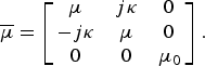
The ferrite-tuned coaxial cavities used in particle accelerators serve the function of creating an RF voltage across a gap on the path of the beam, which, at the peak of its phase cycle, exerts the accelerating force on the charged particles (e.g. electrons) forming the beam. Tuning the oscillation frequency is therefore required for the voltage signal to be able to stay in synchronization with the gradually increasing “passing frequency” of the particle beam. Such a cavity can be constructed similar to the shortened coaxial resonators of coaxial combline filters, with the only difference being the ferrite filling inside the coaxial section. The ferrite is biased into saturation under a DC magnetic field of H 0. With reference to the cylindrical geometry of the cavity, an axially aligned H 0 is preferred as this yields higher unloaded Q factors [Reference Earley, Thiessen, Carlini and Potter22]. In this case, the ferrite's magnetic permeability exhibits non-isotropic (in fact gyrotropic) characteristics in a Polder tensor form [Reference Polder24], i.e.
 $$\overline \mu = \left[ {\matrix{ \mu & {j\kappa} & 0 \cr { - j\kappa} & \mu & 0 \cr 0 & 0 & {{\mu _0}} \cr}} \right]. $$
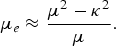
Here, μ and κ are functions of the bias field magnitude H 0, ferrite's saturation magnetization M s, and the frequency [Reference Polder24], while μ 0 is the permeability of the free space. It was shown in [Reference Brodwin and Miller25] that a ferrite-filled coaxial transmission line, under the stated conditions, sustains a quasi-transverse electromagnetic (quasi-TEM) mode of wave propagation with an equivalent permeability of
 $${\mu _e} \approx \displaystyle{{{\mu ^2} - {\kappa ^2}} \over \mu}. $$
Hence the cavity, which is a segment of this type of transmission line short-circuited at one end and terminated with a capacitive gap at the other, resonates in a similar fashion to the cavity made of the hollow line, at the frequency where the transmission line and capacitor susceptances add up to zero. The added benefit is that the resonance frequency f 0 can now be tuned by controlling H 0. Since in the described configuration the biasing magnetic field (axial) is perpendicular to the RF magnetic field (azimuthal), the ferrite is said to be transversely or perpendicularly biased. A simplified drawing and the equivalent circuit diagram for this type of a resonator can be seen in Fig. 1.
Simplified cross-sectional drawing of a ferrite-loaded shortened coaxial resonator with transverse magnetic bias, and its equivalent circuit with the corresponding parts matched. The transmission line section has a characteristic impedance Z 0 and a phase constant β that are functions of frequency and M s as well as H 0, which can be changed to tune the resonator.

Such a resonator was designed and constructed for evaluation purposes. To be able to reveal the high-Q potential of the technology, a ferrite with a low ferromagnetic resonance linewidth (ΔH) was chosen, as this reduces the magnetic losses [Reference Cruickshank26]. Material NG-1001 from National Magnetics Group [27] was used, whose parameters can be seen in Table 1. The housing, which was manufactured in two parts by machining bulk brass, was plated with silver to reduce the conductor losses. Two cylinder-shaped rare-earth permanent magnets of 45 mm diameter and 30 mm height were used as the bias source. Tuning was then performed by placing the magnets at equal distances from the ferrite below and above the cavity in axial alignment with it, and changing the distances in a synchronized manner, preserving the equality. The characterization was done by reflection measurements on a single-port, loosely coupled design using a vector network analyzer (VNA). The measured reflection coefficients for varying levels of magnetic bias (labeled A to K) are shown on the Smith chart in Fig. 2. Each one of these curves traces a circle in the vicinity of its resonance. The resonance parameters (the resonance frequency f 0, the unloaded quality factor Q 0, and the coupling coefficient k c) can be extracted from the measured data by analyzing these circles’ positions and dimensions as well as the frequency ranges they span [Reference Kajfezm and Hwan28].
The measured reflection coefficient curves of the loosely coupled resonator in bias states A to K with spatial distributions of gradually increasing H 0.
Specification of intrinsic parameters for the NG-1001 ferrite.

The resonances were analyzed by fitting the best-matching circles to the measured data using the method in [Reference Kasa29]. The variation of Q 0 with respect to f 0 is shown in Fig. 3. It can be seen that Q 0 does not remain constant across the tuning range. While in the lower half it increases with the decreasing low-field loss in the ferrite due to increasing but still partial magnetization [Reference Schloemann30], in the upper half where the ferrite is already in deep saturation and the magnetic losses are minor, its slope reduces. Towards the upper end of the range, Q 0 starts decreasing due to the now-dominating conductor loss of the cavity surface, which is fully consistent with [Reference Earley, Thiessen, Carlini and Potter22]. In order to determine the tuning range, a limit for the minimum acceptable Q 0, denoted here by Q 0,min., was chosen, and since high-Q operation is of particular interest, this level was set to 2000 for comparability with practical requirements. Evaluated this way, the tunability was measured to be 42% (49% at Q 0,min. = 1000).
The f 0 versus Q 0 curve of the ferrite-tuned resonator obtained by measurements, showing the tunability figures achieved for Q 0,min. = 1000 and Q 0,min. = 2000. The data points labeled A to K correspond to the measured responses plotted in Figure 2.
While the tuning range is restricted on the low side of the spectrum by the Q 0 drop, on the high side the limit is found to be the required bias field strength. The tunability could possibly be improved by further optimization of the biasing magnetic circuit.
III. FILTER DESIGN AND PERFORMANCE
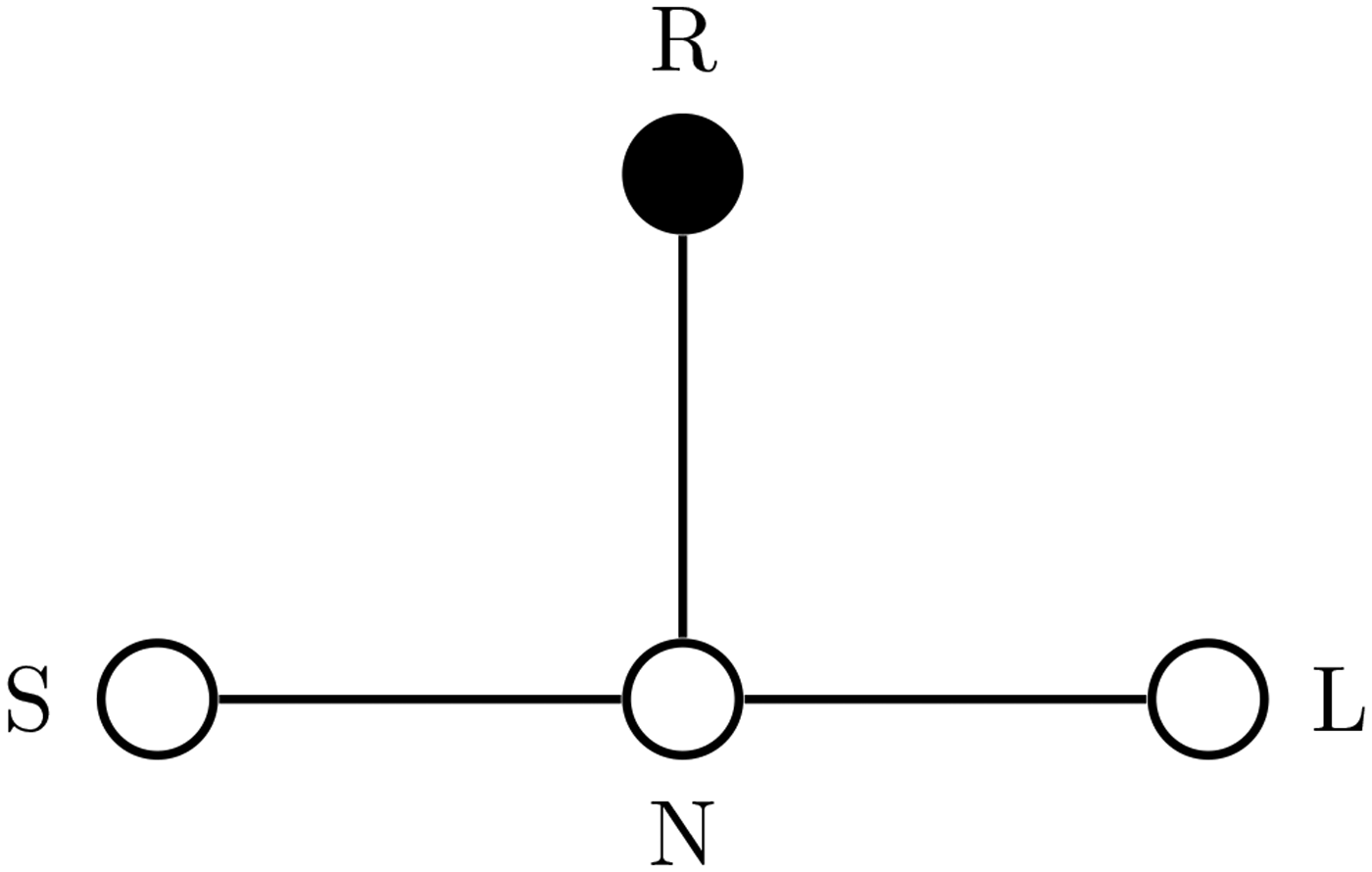
Designing a filter from resonators comprises synthesizing a coupling matrix and implementing the corresponding coupling coefficients for the inter-resonator and external couplings. For simplicity in illustrating the filter tuning method, here, a single-pole notch filter is presented, whose coupling topology diagram is shown in Fig. 4. This topology, which incorporates a non-resonating node N, has an (N + 2) × (N + 2) (extended) coupling matrix of
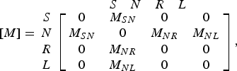 $$\eqalign{& [M] = \matrix{ {} \cr S \cr N \cr R \cr L \cr } \matrix{\matrix{S & N & R & L \cr }\cr \left[ {\matrix{ 0 & {M_{SN} } & 0 & 0 \cr {M_{SN} } & 0 & {M_{NR} } & {M_{NL} } \cr 0 & {M_{NR} } & 0 & 0 \cr 0 & {M_{NL}} & 0 & 0 \cr } } \right]\comma}} $$
where the indices S, N, R, and L stand for source, non-resonant node, resonator, and load, respectively. It should be noted that the source-to-N and N-to-load couplings M SN and M NL are unity due to the notch characteristic of the filter. The N-to-resonator coupling M NR, on the other hand, is set to yield a freely chosen (for the demonstration's sake) loaded quality factor Q L of 12.1 at an approximately mid-range frequency of 960 MHz.
The topology diagram of the filter showing the couplings to be established.
Ferrites typically have relative permittivity values in the range of 9–18 [Reference Okamura, Fujimura and Date31], and in the present case it is 14. Being surrounded by the unity relative permittivity of the air, they contain the field lines densely within themselves. Therefore coupling microwave energy in and out of ferrite-loaded resonators may be difficult using coupled transmission line structures. To be able to obtain the required amount of coupling strength, the present design utilizes tapping into the resonator's inner conductor, through a hole drilled radially through the ferrite, where the inner pin of a coaxial connector is brought into direct contact the inner conductor of the coaxial cavity. The non-resonant node with a branch-out and with M SN = M NL = 1 is realized by a coaxial T-connector. The level of M NR, on the other hand, can be adjusted by setting the height of the tap point along the length of the resonator. The three-dimensional (3D) finite-element method (FEM) electromagnetics solver model of the design and a photo of the fabricated filter can be seen Fig. 5.
The 3D model of the design on the FEM solver and a photo of the manufactured filter. The inner diameter of the coaxial resonator and the ferrite measure 12 mm; the outer diameter of the ferrite, 28 mm; that of the coaxial resonator, 32 mm; the resonator length, 23 mm; the ferrite's length, 22 mm; the capacitive gap, 2 mm; and the tap height (from the shorted end), 12.5 mm.
The fabricated prototype was measured by a VNA under varying levels of magnetic bias field strengths obtained using the same biasing/tuning scheme with the permanent magnets. Figure 6 shows the response curves of bias states 1–6 with gradually increasing H 0 distributions, where it is seen that the notch can be tuned from about 813 to 1180 MHz, corresponding to a tuning ratio of 1:1.45, or 45%. The variation of Q 0 with f 0 (first increasing, later saturating) can be identified in the way the notch depth first increases, and later stabilizes as the notch frequency is tuned upwards. Passband (off-resonance) insertion loss gradually decreases from 0.2 dB at state 1 to vanishingly small at states 3–6.
Measured transmission (solid) and reflection (dashed) characteristics of the tunable notch filter in bias states 1–6, demonstrating the tuning range and the loss characteristics.
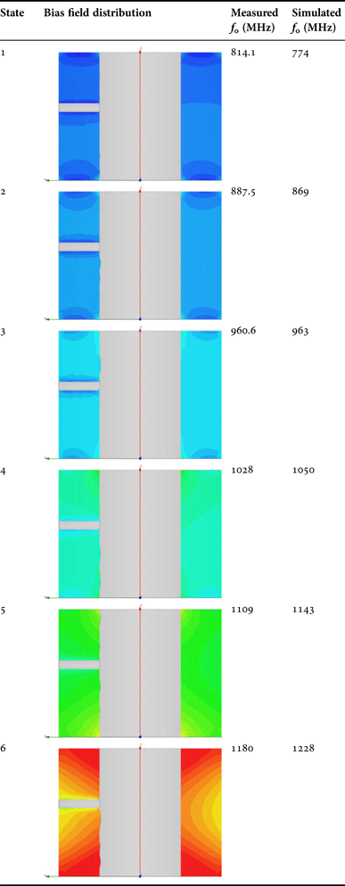
In general in ferrite-tuned applications, biasing the ferrite uniformly would be ideal. In this design, due to the large size of the ferrite as well as the efforts to keep the magnetic bias source simple, a fully uniform bias field distribution was not achieved. It is therefore impractical to try to construct a tuning curve showing the notch frequency against a single scalar variable such as the magnitude of the DC magnetization. The resonance frequency is rather a function of the spatial distribution of the bias field inside the entire ferrite volume. This distribution can not be measured directly (since it is inside a solid volume), but it can be simulated very accurately by a magnetostatic solver, and the obtained non-uniform distributions of different bias states can be used to relate the bias information to the notch frequency. The magnetostatic simulations can also be used as the basis for the electromagnetic simulation in the following step. The results of this co-simulation approach are presented in Table 2 in comparison with the measured tuning characteristics for the bias states 1–6 of Fig. 6. For the explained reason, these bias conditions cannot be identified by a single measure, but are rather distinguished by the H 0 distributions within the ferrite's cross-section.
The simulated H 0 distributions across the ferrite cross-section and the comparison of the measured and simulated notch frequencies of the tunable filter for the bias states 1–6.
The inhomogeneity of the bias can be clearly seen. The color scale is from 100 Oe (blue) to 3200 Oe (red).
It is seen that the simulated estimates for the tuned notch frequency lie within the −4.9% to +4.1% range of accuracy with respect to the measurement reference. The error is thought to originate from the rather high manufacturing tolerances in the ferrite insert's dimensions exceeding half a milimeter and the shape irregularities thereby introduced.
IV. DISCUSSION
The significance of the presented tunable filter technology lies primarily in its balanced compromise between tunability and the unloaded Q values of the resonators. Although many other tuning methods may yield either higher resonator Q values or broader tunability alone, most often the second parameter is compromised, resulting in filters failing to meet the specification requirements. Tuning filters making use of transversely biased ferrite-loaded shortened coaxial resonators, on the other hands, delivers reasonably wide tunability and moderately high resonator Q values at the same time. A comparison of the performance with selected competitive filter tuning technologies from the literature is given in Table 3.
Comparison of selected tunable filter technologies.
The scatter plot of tunability versus resonator Q 0,min. in Fig. 7 shows that transversely biased ferrite-tuned coaxial filters, together with the YIG filters, are the closest two to the desirable area (marked green) in terms of filter design for tight requirements. YIG resonators were earlier found to be strongly dependent on fine manufacturing precision in order to deliver the reported high-Q 0 values [Reference Carter20]. In contrast, the presented technology is demonstrated to not have a similar sensitivity, and stands to be a strong candidate that is shown to effectively lend itself to practical low-loss tunable filter design.
Scatter plot of tunability versus resonator Q 0,min. comparing the tunable filter technologies from [Reference Naser-Moghadasi and Sadeghzadeh-Sheikhan8, Reference Park, El-Tanani, Reines and Rebeiz9, Reference Yassini, Smith and Kellett11, Reference Liu, Katehi, Chappell and Peroulis13–Reference Arif, Irshad, Liu, Chappell and Peroulis16, Reference Petrov, Alford, Buslov, Keis, Kotelnikov, Kulik and Kozyrev19, Reference Blair32, Reference Poplavko, Prokopenko, Molchanov and Dogan33] and the present work. Although vaguely defined, the upper right quarter corresponding to high-Q 0,min. and high tunability is highlighted as the “desirable area”.
V. CONCLUSION
A low-loss, continuously tunable filter has been presented in this work. Ferrite-loaded shortened coaxial resonators have been utilized in the design of tunable filters for the first time. The fabricated single-pole filter was demonstrated to exhibit a resonator Q 0 larger than 2000 within a tuning range of at least 42%. Its tuning behavior was expressed in terms of the non-uniform bias field distribution in the ferrite body. It is worth noting that the presented filter tuning method, together with the tapped couplings can be used to design tunable bandpass filters with similar favorable tunability and loss characteristics.
ACKNOWLEDGEMENTS
This work was conducted within MTI Radiocomp, thanks to the support from the Danish Ministry of Higher Education and Science, under the Industrial Ph.D. program.
Öncel Acar received his B.Sc. degree in Electrical and Electronics Engineering from Middle East Technical University (METU) in Turkey in 2007, and his M.Sc. degree in Wireless Engineering from Technical University of Denmark (DTU) in 2010. He is presently employed as a Research Engineer at MTI Radiocomp, while also being enrolled as a Ph.D. student at the Department of Electrical Engineering at DTU, under the Industrial Ph.D. scheme of Innovation Fund Denmark. His research focuses on high-performance tunable microwave filters.
Tom K. Johansen received his M.S. and Ph.D. degrees in Electrical Engineering from the Technical University of Denmark, Denmark, in 1999 and 2003, respectively. In 1999 he joined the Electromagnetic Systems group, DTU Elektro, Technical University of Denmark, Denmark, where he is presently an Associate Professor. From September 2001 to March 2002 he was a Visiting Scholar at the Center for Wireless Communication, the University of San Diego, California. From November 2012 to February 2013 he spent a sabbatical at the Ferdinand Braun Institute (FBH), in Berlin, Germany. His research areas include the modeling of HBT devices, millimeter-wave and sub-millimeter-wave integrated circuit design, and reconfigurable microwave components.
Vitaliy Zhurbenko received his M.Sc. degree from the Kharkiv National University of Radio Electronics in 2001, and the Ph.D. degree from the Technical University of Denmark in 2008, all in Electrical Engineering. In 2005, he joined the Technical University of Denmark, where he is presently an Associate Professor. His present research and teaching interests include microwave and millimeter wave sensing for biomedical and security applications; microwave and millimeter-wave components and integrated circuits for instrumentation applications; antennas and passive circuit design and characterization; magnetic resonance technology.