I. INTRODUCTION
The precipitation of nanometer-sized Cu-rich precipitates or clusters is of considerable technical importance and scientific interest in high-strength low-alloy (HSLA) steels.Reference Zhang, Liu, Wen, Hirata, Guo, Chen, Chen and Chin1–Reference Misra, Jia, Malley and Jansto3 During continuous cooling transformation, Cu precipitation significantly correlates with austenite decomposition kinetics and usually occurs by interphase precipitation through the redistribution and partitioning of Cu between ferrite and untransformed austenite.Reference Liu, Liu and Xiong4,Reference Liu, Liu, Gu and Liu5 The Cu precipitation characteristics in aspect of compositions, sizes, and morphology depend on the actual cooling rate.Reference Liu and Zhao6 The Cu precipitates generally exhibited a constant crystallographic orientation within ferrite grains, and were arranged in rows in association with the ferrite/austenite growth interface.Reference Thompson and Krauss7 In the case of quench-aging process, Cu precipitation is greatly associated with carbide formation, because the potential crystallographic defects in martensitic structure such as dislocations and low-angle martensite lath boundaries usually act as preferential nucleation sites for the co-precipitation of Cu-rich phases and carbides.Reference Liu and Zhao8–Reference Tiemens, Sachdev, Mishra and Olson10 Besides, the effects of solute atoms on the nature of Cu precipitation have been studied. Ni is found to facilitate Cu precipitation and thus is beneficial to strength improvement.Reference Zhang, Liu, Miller, Wang, Wen, Fujita, Hirata, Chen, Chen and Chin11–Reference Jiao, Luan, Zhang, Miller, Ma and Liu13 The interactions of Cu precipitation with these nanoscale features are prevailing in steel fabrication during traditional thermomechanical processing and quench-tempering heat treatment.
A small amount of austenite plays an important role in the development of ductile and tough and yet high strength steels with a martensitic matrix.Reference Yuan, Ponge, Wittig, Choi, Jiménez and Raabe14,Reference Raabe, Ponge, Dmitrieva and Sander15 The design strategy usually involves a multistage heat treatment of steels with addition of Ni and Mn. These austenite-stabilizing elements exhibit strong segregation at the boundaries in martensitic microstructures and promote the occurrence of martensite to austenite reversion. Thus, the martensitic structure is changed following solute enrichment at the crystallographic boundaries. Raabe et al. termed this new approach as “segregation engineering,” and pointed out that the formation of nanosized austenite reversion layers at segregation decorated martensite lath boundaries opens a new pathway in the design of ductile martensite.Reference Raabe, Sandlöbes, Millán, Ponge, Assadi, Herbig and Choi16 In fact, the toughening mechanism has been used in the development of high Ni cryogenic steels, the heat treatment schedule of which contains an additional intercritical tempering between conventional quenching and tempering processes.Reference Kim, Syn and Morris17 The stability of the reversed austenite responds to the low-temperature toughness.Reference Fultz, Kim, Kim, Kim, Fior and Morris18,Reference Fultz and Morris19
However, precipitation hardening leading to high strength often reduces ductility and toughness, i.e., there are conflicts between strength and toughness.Reference Ritchie20 The quench-tempered HSLA steels at peak strengthening by a fine dispersion of Cu precipitates usually possess undesired impact toughness.Reference Mujahid, Lis, Garcia and DeArdo21 Nakada et al.Reference Nakada, Syarif, Tsuchiyama and Takaki22 found that addition of Cu in 9% Ni steel refines the dual-phase microstructures consisting of Cu precipitate dispersed martensitic matrix and reversed austenite. The reversed austenite and Cu precipitates are formed during intercritical tempering and conventional tempering, respectively. The microstructures significantly improve the strength–toughness balance. Besides, the intercritical tempering effectively improves the low-temperature toughness of high-strength ship hull steels by reversed austenite, while simultaneously sacrificing limited Cu precipitation strengthening.Reference Luo, Yang, Chai and Su23 It is suggested that an additional intercritical tempering of quench-tempered Cu-containing alloyed steels contributes to the substantial improvement of mechanical properties especially of yield ratio and low-temperature toughness.Reference Chen, Cheng and Liu24
In the present study, we concern on the martensite to austenite reversion at the possible prior austenite boundaries, martensite packet, block, or lath boundaries during intercritical tempering, and the Cu precipitation in association with the phase transformation during subsequent conventional tempering.
II. EXPERIMENTAL
A. Materials
The experimental steel was received in as-rolled plate with 32 mm in thickness from the Institute of Research of Iron and Steel (IRIS), Shagang Group, China. The steel, with a composition of 0.04 C, 0.25 Si, 0.89 Mn, 1.54 Cu, 3.51 Ni, 0.59 Mo, 0.49 Cr, 0.050 Nb, 0.011 Ti, 0.033 Al, 0.008 P, and 0.005 S (wt.%), was fully austenitized and solutionized at 900 °C for 30 min followed by quenching in water at 25 °C. An intercritical tempering at 725 °C for 1 h followed by water quenching was introduced before conventional tempering at 500 °C for 1 h. The A c1 temperature was measured to be about 692 °C by dilatation method, which was slightly higher than that of a HSLA steel with similar nominal composition.Reference Mujahid, Lis, Garcia and DeArdo21
B. Characterization techniques and methods
The microstructure was observed on the polished sample surface etched in a 4% nital solution with an optical microscope (OM), and was also subjected to microhardness measurement at 10 kg load using a Vickers hardness tester. The distributions of crystallographic orientation and grain boundary in the microstructure were examined by the electron backscattering diffraction (EBSD) with a field-emission scanning electron microscope (NOVA NanoSEM 230, FEI, Portland) at 20 kV. The transmission electron microscopy (TEM) observation is conducted in a JEOL 2010 F (JEOL, Tokyo, Japan) at 200 kV. The thin foil for TEM was prepared by mechanically grinding sample slices to 80-μm-thick and twin-jet electropolishing in a mixture of 90% alcohol and 10% perchloric acid at −30 °C under 50 V. The atom probe tomography (APT) experiment, using an advanced local electrode atom probe (LEAP, 3000 HR, CAMECA, Gennevilliers, France), was performed at a residual pressure of 3 × 10⁻⁹ Pa and a specimen temperature of −223 °C, and with a pulse repetition frequency of 200 kHz, a pulse-voltage to dc-voltage ratio of 15%. The needle-like specimens for APT were prepared by using standard two-stage electropolishing method at room temperature.Reference Miller25 Data analysis was performed by using the Cameca Integrated Visualization and Analysis software.
III. RESULTS AND DISCUSSION
A. Optical microstructures and microhardness
Figure 1 represents a series of optical micrographs of the experimental steel. The as-quenched microstructure [Fig. 1(a)] after the solution treatment consists of a typical lath martensitic structure with some visible linear-array retained austenite located at the lath boundaries. The quench-tempering microstructure exhibits a recovered lathlike structure with disappearing retained austenite, but it has not recrystallized because the prior austenite grain boundaries do not undergo any remarkable changes [Fig. 1(b)]. An intercritical tempering followed by water quenching brings about an alternating black–white dual phase microstructure [Fig. 1(c)], which is essentially composed of ferrite (white) and austenite or martensite (dark) that is probably formed on quenching. A conventional tempering of the microstructure cannot lead to the totally decomposition of austenite or recovery of martensite, which still looks dark at the martensite lath boundaries [Fig. 1(d)]. It is suggested that the final microstructure after the multistep heat treatment process consists of potential tempered martensite or ferrite and austenite/martensite, which is different from that formed during conventional quench-tempered process [Fig. 1(b)].
Optical images showing the microstructures of the experimental steel: (a) as-quenched from full austenite; (b) tempered at 500 °C for 1 h after quenching; (c) intercritical tempered at 725 °C for 1 h after quenching; (d) tempered at 500 °C for 1 h after quenching and intercritical tempering.

The microhardness values are labeled in the corresponding optical images. In the conventional quench-tempering process, the high microhardness of the as-quenched microstructure mainly arises from highly dislocated lathlike martensite structure. However, a subsequent tempering usually leads to peak hardening by nanometer-sized precipitates, although a recovery of martensite structure accompanied with a substantial decrease of dislocation density simultaneously takes place. As for the intercritical quench-tempering process, the overall microstructural morphology is not distinctly changed except the visible detected reversed austenite or martensite in Figs. 1(c) and 1(d), comparing to its separate counterparts in Figs. 1(a) and 1(b). It is consequently suggested the precipitation of reversed austenite at martensite lath boundaries or prior austenite grain boundaries that occur during intercritical tempering responds to the changes in microstructures. The dual-phase structures are thought to enhance the hardness by increasing the volume of boundaries and thus the refined equivalent grains. However, the microstructures exhibit lower hardness, which probably is attributed to the following two reasons. First, softer matrix of ferrite crystals with low density of dislocation is formed in association with martensite to austenite reversion during intercritical tempering. Second, Cu precipitation strengthening effect decreases during conventional tempering, because non-ignorable amount of Cu atoms are consumed by segregating into reversed austenite.
B. EBSD microstructures
Figure 2 gives the detailed microstructures that develop during intercritical tempering and following conventional tempering. Because tempering at 500 °C for 1 h only causes a partial recovery of martensitic structures with merely a decrease in the density of dislocations, the microstructural configuration presented by EBSD such as phase constituents and grain boundary is indeed not the changes during this short period of tempering. Besides, the precipitation of Cu-rich phases cannot be well verified because of the limited resolution of EBSD technique. Thus, the microstructures here also represent that formed during intercritical tempering.
EBSD microstructures of the experimental steel with a multistep heat treatment process of water-quenched from 900 °C, intercritical tempering at 725 °C for 1 h, and conventional tempering at 500 °C for 1 h. (a) Orientation imaging map; colors of different martensitic crystals showing the crystallographic orientations as indicated in the stereographic triangle. (b) Grain boundary map; coloring criterion of boundary: 5° ≤ θ < 15°, gray lines; 15° ≤ θ < 45°, red lines; 45° ≤ θ, blue lines.
The inverse pole figure color map in Fig. 2(a) shows the morphology and crystallographic features of the microstructures. The colors correspond to the crystallographic orientation normal to the observed plane, as indicated by the stereographic triangle in the inset. The grain boundary characteristics in the microstructures are illustrated in Fig. 2(b). The red lines denote high-angle grain boundaries with misorientation angles between 15° and 45°, whereas the gray and blue lines show low-angle boundaries with lower misorientation angles (<15°) and the other high-angle boundaries with higher misorientation angles (>45°), respectively. The microstructures still apparently keep a martensitic lathlike morphology. However, recrystallization of martensite starts in some areas at prior austenite grain boundaries and at some martensitic block or packet boundaries. Most of the recrystallized grains have irregular spherical shapes and relatively small sizes, which are distinguished by high-angle boundaries as indicated by blue and red lines. Previous studiesReference Tsuchiyama, Natori, Nakada and Takaki26 have demonstrated that the ultra-low carbon lath martensite recrystallizes only through bulging of the pre-existing mobile grain boundaries with misorientation angles between 15° and 45°, which often possess only a small proportion of the whole grain boundaries. This suggests that only limited prior austenite grain boundaries and block or packet boundaries of martensite cause bulging and form recrystallized grains, leading to the low frequency of recrystallized ferrite nucleation. The growth of the recrystallized grains is substantially suppressed after nucleation, as most of the small grains are divided by high-angle boundaries with low mobility indicated by blue lines. Besides, the orientations of the recrystallized grains have several variants with that of the adjacent tempered martensite, as shown in Fig. 2(a).
C. Scanning transmission electron microscopy microstructures
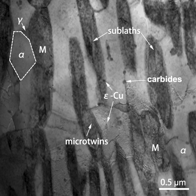
The scanning transmission electron microscopy (STEM) micrograph in Fig. 3 reveals the microstructures in Fig. 2 at a finer scale. The image clearly shows dual-phase structures consisting of ferrite (gray) and tempered martensite (dark) by utilizing the Z contrast difference. The martensite laths are observed to be several micrometers long and approximately 0.5 µm wide or less. The lathlike martensite mostly seems to be formed in the ferritic matrix, and is separated by low-angle boundaries. Compared with the surrounding matrix, the lath martensite is highly dislocated. Several sublaths and microtwins located respectively within and at the vicinity of martensite laths are observed. Apart from the elongated structures, equiaxed grains are also seen with one is outlined by high-angle boundaries marked by a dashed line, which probably correspond to small recrystallized ferrite grains observed in EBSD images in Fig. 2. Small amount of blocky retained austenite is detected between the martensite lath and the recrystallized ferrite grain. The retained austenite is free of dislocations and precipitates. However, a high number of ε-Cu precipitates are observed in both ferritic matrix and lath martensite. Comparatively, the precipitates in ferritic matrix are smaller in sizes and lower in number density. However, some nanometer-sized Cu-rich clusters if any cannot be readily distinguished by TEM due to the high coherence with the body-centered cubic structure ferritic matrix. Some precipitates located at the boundaries usually have large sizes. These precipitates are rich in C by x-ray diffraction analysis and are considered as carbides.
STEM image showing ferrite (α)–martensite (M) dual-phase microstructures with retained austenite (γ), ε-Cu precipitates, and carbides.
During intercritical tempering at 725 °C, new austenite that is formed by martensite to austenite reversion is predominantly located at prior martensite lath boundaries and austenite grain boundaries,Reference Hara, Maruyama, Shinohara, Asahi, Shigesato, Sugiyama and Koseki27 which act as preferred sites for heterogeneous nucleation. The reversed austenite becomes rich in solutes especially Ni, Mn, and Cu by solute redistribution between the reversed austenite and ferritic matrix, which consequently improves the stability of the austenite. Depending on the actual volume fraction and the resulting stability that is in direct proportion to solute enrichment, the reversed austenite retains to ambient temperature or alternatively transforms to other phases, such as martensite, upon cooling. In the present experimental steel, a ferrite–martensite dual-phase structure is obtained by intercritical tempering at 725 °C that is above the A c1 temperature but slightly higher than the right temperature to obtain stable austenite. A subsequent conventional tempering at 500 °C leads to the precipitation of Cu-rich phases and carbides especially in the solute-rich martensite or at the ferrite–martensite heterophase interfaces. However, the conventional tempering cannot change the fine dislocation and sublaths structures in martensite.
D. APT characterization
Figure 4 gives APT reconstructed maps showing an overview of the spacial distributions of Cu, C, Ni, Mn, Cr, and Mo atoms in the quenched, intercritical tempered, and conventional tempered experimental steel. The segregation of C outlines a possible crystallographic boundary. It is obvious that the precipitation of Cu-rich phases occurs in the matrix and at the C-rich boundary, at where the sizes of the Cu-rich phases are comparatively larger than that in matrix. Besides, the segregation of non-carbide-forming element of Ni and carbide-forming elements of Cr and Mo as well as Mn atoms also takes place at the C-rich boundary. The segregation or clustering of Ni and Mn is usually associated with Cu precipitation, since Ni and Mn are considered to be enriched in Cu nuclei at the early stage of precipitation and are prone to segregation at the Cu precipitate/matrix heterophase interface.Reference Zhang, Liu, Miller, Wang, Wen, Fujita, Hirata, Chen, Chen and Chin11,Reference Liu, Gu and Liu12,Reference Kolli and Seidman28,Reference Kolli, Mao, Seidman and Keane29 Thus, the enhanced concentration of Ni and Mn is partly induced by the large Cu precipitates at the boundary. However, the Ni and Mn content around the boundary are seemingly higher than that in the left matrix. A rotational view of Cr and Mo atom maps shows no solute clustering at the boundary. Unlike our previous observation in a similar steel aged for 4 h,Reference Liu and Zhao8 the initial nucleation of carbide is not taking place due to short tempering time.
3D reconstruction atom maps of Cu, C, Ni, Mn, Cr, and Mo, showing the precipitation of Cu in matrix and at the C-rich boundary, and the segregation of Ni, Mn, Cr, Mo atoms at the boundary.
1. Overview of the microconstituents at atomic scale
Figure 5 shows APT reconstructed 3D distribution of the features of the C-rich boundary and Cu-rich phases in the ferritic matrix. A discreet observation reveals that some small C-rich zones are located in the upper region of the APT map, i.e., in the martensite (M) above the boundary. Besides, the Cu-rich phases in this region are generally larger than that in the lower region where some of Cu clustering zones even cannot be enveloped by 10 at.% isoconcentration surfaces. From these atom distributional characteristics, the upper region is considered as the solute-rich tempered martensite that corresponds to the STEM observation in Fig. 3. However, there is no distinct concentration gradient between α-Fe matrix and tempered martensite, which is probably attributed to the Cu precipitation and the C segregation at the boundary. The martensite transformed from the reversed austenite that is formed during intercritical tempering is mainly rich in austenite stabilizers of C, Ni, Mn, Cu etc. However, Cu precipitation during conventional tempering certainly consumes a significant amount of Cu as well as Ni and Mn, since which are prone to segregate at the Cu precipitate/matrix heterophase interphase.Reference Kolli and Seidman28,Reference Kolli, Mao, Seidman and Keane29 At the same time, C segregation or clustering even in autotemperingReference Hutchinson, Hagstroöm, Karlsson, Lindell, Tornberg, Lindberg and Thuvander30 and carbide precipitation during temperingReference Thompson and Krauss7 also lower C concentration in solid solution. All the segregation and precipitation reactions lead to the depletion of the tempered martensite that is inherited from reversed austenite on quenching. Consequently, the observed boundary in Fig. 5 proves to be low-angle ferrite–martensite boundary.
APT reconstructed 3D distribution of atomic-scale substructures of C-rich boundary and Cu-rich precipitates (on boundary) or clusters (in α-Fe matrix) delineated by 2 at.% C and 10 at.% Cu isoconcentration surfaces, respectively. Two subset boxes as regions of interest (ROIs) (ROI-1 as boundary and ROI-2 as Cu-rich precipitate) are selected for detailed compositional analysis.
2. Compositional variants at the ferrite–martensite boundary
The corresponding composition profile of ROI-1 in Fig. 6 clearly shows the partitioning behaviors of the solute elements at the boundary, where any Cu-rich phases are artificially omitted. Ni and Mn are both austenite stabilizers and are enriched at the boundary, which is probably due to an enhanced concentration in the martensite nearby. Cu is also an austenite stabilizer, but no Cu segregation is observed, which is attributed to the overall Cu precipitation at the boundary, as shown in Fig. 5. A shift segregation of Cr and Mo as well as C segregation at the boundary is derived by preferential nucleation of carbides. Comparatively, Al and Si appear to be reluctant to segregate at the boundary.
One-dimensional composition profile across the boundary in ROI-1 in Fig. 5.
The compositional profile of the selected elliptical Cu precipitate in ROI-2 at the boundary is shown in Fig. 7. The figure indicates that Ni and Mn surprisingly segregate only at the upper side of the precipitate, which is inconsistent with the previous studiesReference Kolli and Seidman28,Reference Kolli, Mao, Seidman and Keane29 that Ni- and Mn-rich shell is usually formed around especially large-sized Cu precipitates. The unsymmetrical Ni and Mn enrichment probably results from the different contents of Ni and Mn available in lower solute-depleted ferrite region and upper solute-enriched martensite region. The phenomenon is also found in the segregation behavior of C, Cr, and Mo, which are not considered to be related to Cu precipitation but slightly higher in content at the upper side of the Cu precipitate. In contrast, Si and Al seemingly segregate at both sides of the elliptical Cu precipitate/matrix heterophase interfaces.
One-dimensional composition profile across the Cu precipitate at the boundary in ROI-2 in Fig. 5.
E. Microstructural evolution with the multistage heat treatment
Figure 8 gives a series of schematic diagrams showing the possible microstructures developed in different heat treatment stages. According to the Fe–Cu phase diagram, austenitizing temperature of 900 °C is high enough to have all the Cu in solution and the followed water-quenching process entirely suppresses the Cu precipitation, thus leading to the formation of Cu supersaturated dislocated lathlike martensite as shown in Figure 8(a). A conventional tempering of the martensitic structure at a proper temperature makes Cu precipitate out from solid solution as shown in Figure 8(b). The Cu precipitates are formed on dislocations and low-angle martensite lath boundaries and generally have similar sizes independent on the nucleation sites.Reference Liu and Zhao8 The dispersed spherical Cu precipitates exert a significant contribution to strength. Alternatively, an intercritical tempering of the martensitic structure at ferrite–austenite two-phase region brings about the formation of Cu-rich reverse austenite predominantly at the prior martensite lath boundaries. The reverse austenite remains stable or transforms into martensite on quenching to room temperature, which is dependent on the actual solute enrichments associated with reverse austenite fractions, as shown in Fig. 8(c). Because of enhanced high Cu solubility in matrix and competitive Cu diffusion into the reverse austenite, Cu precipitation is inhibited. A subsequent tempering of the microstructure in Fig. 8(c) will necessarily cause Cu precipitation in both ferrite and martensite as well as at the two phases' boundaries as shown in Fig. 8(d). Cu atoms available in martensite or supplied by decomposition of retained austenite if any, contributes to the rapid nucleation especially at the ferrite/austenite boundaries and fast growth of Cu precipitates. Although the heterogeneously distributed Cu precipitates in aspect of both size and morphology probably contribute comparatively less to strength, the ferrite–martensite dual-phase structure improves the ductility and toughness.
Schematic diagrams of microstructural evolution: (a) as-quenched from full austenite, showing dislocated martensite laths with supersaturated Cu atoms; (b) conventional tempered from as-quenched state, showing Cu precipitation on martensite laths boundary and disappearing dislocation for recovery; (c) intercritical tempered from as-quenched state at austenite–ferrite temperature region followed by water-quench, showing reverse austenite formation and Cu atom segregation at martensite laths boundary; (d) conventional tempered from intercritical tempered state, showing the coarsening of Cu-rich phases at martensite lath boundary and Cu-rich clusters within solute-diluted martensite lath. (The characters of actual substructures such as the morphology and size of Cu-rich phases depend on the temperature and time used in heat treatment. Besides Cu, austenite stabilizers of Ni, Mn, etc. also tend to segregate to martensite lath boundary during intercritical tempering and enrich in reverse austenite.)
IV. SUMMARY
In this study, the Cu precipitation and the martensite to austenite reversion in a Ni- and Cu-containing HSLA steel with a multistage heat treatment were studied using multiscale characterization methods of OM, EBSD, STEM, and APT. The following conclusions were obtained.
(1). An intercritical tempering between the conventional quenching and tempering process has not substantially changed the overall lathlike microstructures, which consists of solute-rich ferrite and solute-dilute martensite dual phases and numerous small recrystallized ferrite grains at the prior austenite grain boundaries and martensite packet or block boundaries.
(2). Cu precipitation occurs during conventional tempering in both ferrite and martensite as well as the low-angle boundaries of the two phases. The Cu-rich phases in ferrite are generally smaller than that in martensite within which more solutes especially of Cu, Ni, Mn, etc. in solid solution are available. The ferrite/martensite boundary induces fast growth of Cu precipitates into an elliptical morphology. The unsymmetrical atom distributions at the precipitate/matrix heterophase interface with higher content of Ni and Mn in martensite side result from the different segregation behaviors of solute atoms at the boundary.
(3). The nature of Cu precipitation is greatly affected by the microconstituents particularly when phase transformation takes place. It is thus effective to regulate Cu precipitation by using appropriate phase transformation to obtain desired mechanical properties and to further develop new general advanced steels.
ACKNOWLEDGMENTS
This work was financially supported by the National Basic Research Program of China under Grant No. 2011CB012904, the National Natural Science Foundation of China under Grant No. 50931003, and the China Postdoctoral Science Foundation under Grant No. 2013M541517. The authors gratefully acknowledge Dr Liu D.S. at Institute of Research of Iron and Steel, Shasteel Group Ltd for providing the materials.