I. INTRODUCTION
Recently short-range connectivity systems have been diversely developed with various specifications such as high/low speed, wideband, low-power consumption, location awareness, and a security [Reference Preradovic, Karmakar and Balbin1–Reference Han, Son and Kim5]. In particular, thanks to the merits of the wideband properties, the physical layer (PHY) technologies with an ultra-wideband (UWB) are popularly used for high-rate UWBs of IEEE 802.15.3a/c [Reference Aiello and Rgerson6, Reference Baykas, Sum, Lan, Wang, Rahman and Harada7], the low-rate, low-power ZigBee/UWB of IEEE 802.15.4/a [8–Reference Flury, Merz and Boudec10] and the wireless body area network (W-BAN) based on IEEE 802.15.6 [Reference Bae, Song, Lee, Cho and Yoo11]. Since the new standard of the IEEE 802.15.6 was released [12], the low-power FM-UWB technology has been issued to be adaptable for the W-BAN applications in low-power consumption signal format, low-spectral power density, and human safety [Reference Imai, Takeuchi, Sakanushi and Iwato13]. Recently, new wideband systems have been researched with the various signal formats in pulse shaping techniques such as impulse [Reference Zhang14–Reference Colli-Vignarelli and Dehollain16], Gaussian [Reference Qin17, Reference Wang18], and chirp signals [Reference Nair, Zheng, Ang, Lian, Yuan and Heng19]. Even though the monocycle pulses are good candidates for an UWB system in terms of better bit-error-rate (BER), multipath interference, and spectrum characteristics [Reference Chen and Kiaei20], they have limitations of a propagation distance [Reference Zhang14] and full integration in CMOS due to large peak amplitude [Reference Qin17, Reference Nair, Zheng, Ang, Lian, Yuan and Heng19]. Therefore, it is required for the new signal format to be verified in the system performances.
In this paper, a wideband RF transceiver system with channel bandwidth (BW) power control scheme is proposed based on IEEE802.15.6. With an optional RF signal on the IEEE standard [12], the proposed system can control the radiating RF power by adjusting the spectral BW, while a conventional system amplifies the channel power by increasing the peak spectral power. Because of this constant spectral power, the unique power control scheme can not only maintain the regulation of the spectral marks, but also make it possible to design a simple and efficient RF front-end system architecture. Furthermore, in the case of power modulation schemes of amplitude shift keying (ASK), the proposed wideband RF carrier (WRC) can maintain the same variation of the signal envelope in a time-domain waveform. Therefore, the back-off margin of power amplifiers can be reduced, which can contribute to low-power design for sensor devices. In addition, the proposed architecture can be designed to realize adaptive reconfigurable RF systems with agile control [Reference Djoumessi, Tatu and Wu21] and modulation schemes [Reference Carlowitz, Esswein, Weigel and Vossiek22]. This paper is organized as follows. Section II introduces the RF system embedding the WRC. In Section III, the proposed system performance and power controllability are evaluated with BER tests, compared with a conventional CW carrier system (CWC). Finally, the commercial feasibility of the proposed system is mentioned in the conclusion.
II. RF TRANSCEIVER SYSTEM DESIGN WITH WIDEBAND RF CARRIER
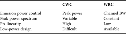
In this section, the proposed connectivity system architecture with the WRC is described. Whereas a conventional system with the CWC has a narrow band spectrum determined by the data-rate, the proposed one with the WRC generates an RF signal BW by the carrier signal BW. Figure 1 presents a comparison of the transmitting power control methods between the CWC and WRC. For the conventional CWC, as the peak power needs to be amplified within the specified spectrum, a power amplifier should be designed with higher linearity. The WRC can control the channel power by adjusting the channel BW with a constant maximum emission power. In the case of the multi-band OFDM UWB, in spite of the various merits, the PHY suffered from the spectral mask violation of OFDM signals as well as high-power consumption. Therefore, because the transmitter can keep the variation of the signal envelope constant and the maximum radiation spectral density fixed, the transmitting amplifiers do not require high linearity or a back-off margin, which makes it possible for the proposed system to be designed with a low-power architecture. In addition, the power control is not performed in the microwave power amplifier, but rather in the local oscillation sub-system. This also allows a low-power consumption system architecture to be achieved, because the BW control is done in low-frequency (LF) devices with efficient DC power consumption. Table 1 summarizes the system characteristics with both types of carriers.
Power control methods of the (a) CWC and (b) WRC.

Characteristics of the CWC and WRC.
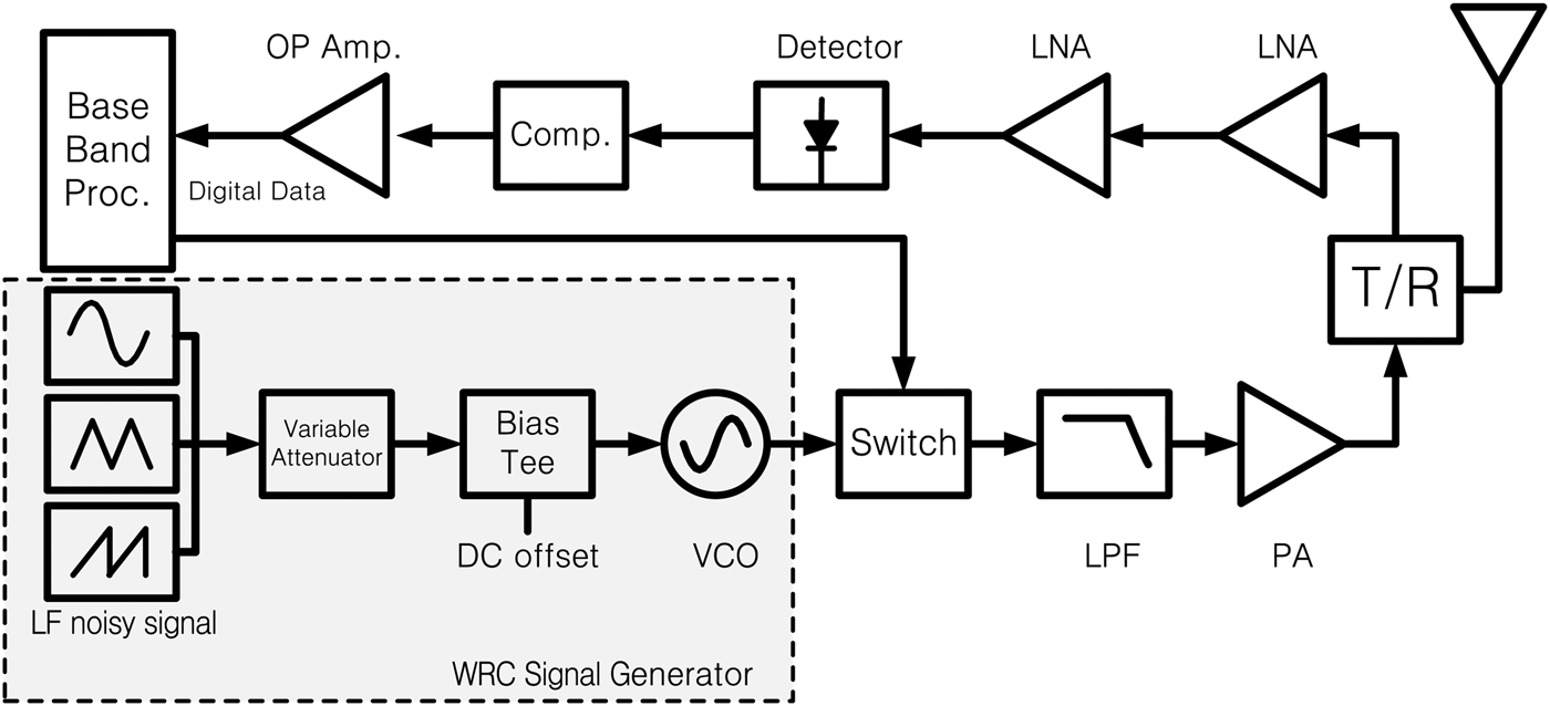
The RF transceiver system is designed with a WRC as shown in Figure 2. The transmitter consists of a WRC signal generator, a switching ASK modulator, an LPF, and an amplifier. The WRC signal generator is implemented by an LF noisy signal generator, a variable attenuator, a bias-tee, and a VCO. The pseudorandom LF noisy signal is constructed by combining sinusoidal-, triangular-, and sawtooth-waves with different periods. The WRC is generated by VCO output, which can control the center frequency by the offset DC provided through a bias-tee and the BW by adjusting the amplitude of the LF noisy signal through a variable attenuator. The WRC signal generator can control the carrier spectrum of the BW from 20 to 100 MHz and the center frequency from 2 to 3 GHz. The ASK modulation scheme is adopted with a switch modulator. The receiver is designed using LNAs, an envelope detector, and a comparator (1-bit ADC), and connected to a digital FPGA board for signal processing.
System architecture with the WRC generation.
III. SYSTEM PERFORMANCE EVALUATION
The performance of the WRC system was evaluated. Two test schemes were employed to evaluate the system operating performance and to provide a comparison of the data transmitting abilities for different power control schemes of the proposed WRC and conventional CWC by BER tests.
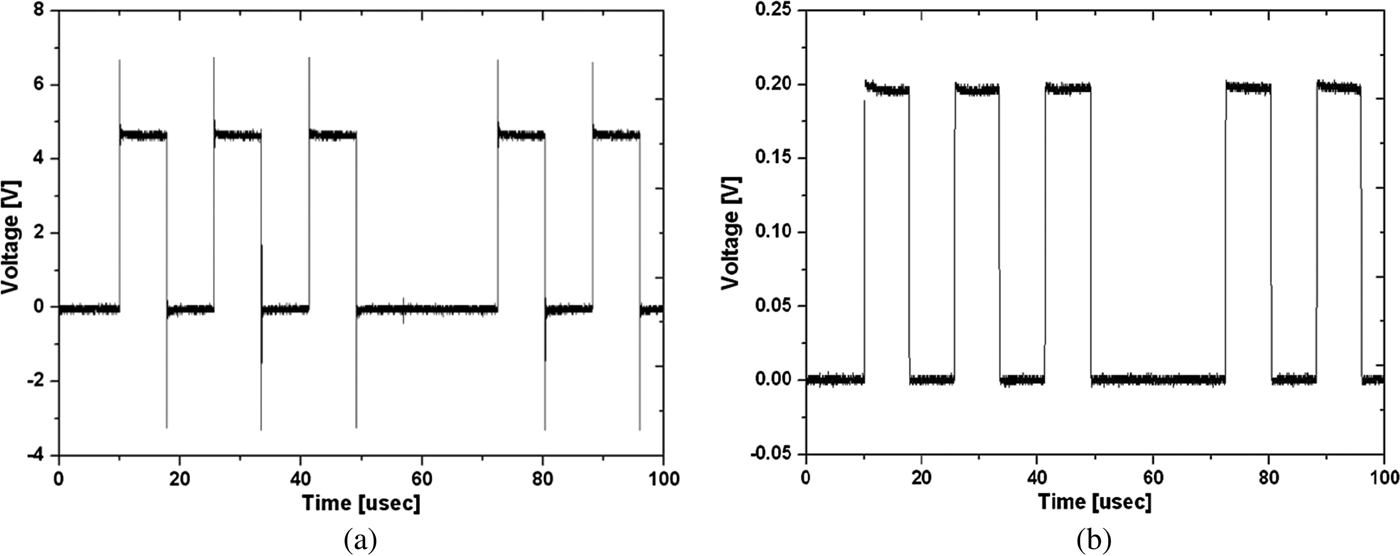
In order to evaluate the system performance of the WRC RF transceiver, the controllable WRC signal generation and digital data transmission were tested. Figure 3 presents the WRC spectra for the BW adjustability for 50, 100, and 200 MHz, and the center frequency tunability of the WRC with the 100 MHz-BW for 2.2, 2.4, 2.6, and 2.8 GHz, respectively. From the flexible spectra, both RF power control and channel selection can be achieved for the RF system applications. For the digital data transmission tests, the WRC signal with a 100 MHz-BW modulated a pseudorandom bit stream (PRBS) with a data-rate of 64 kbps, a 29−1 random pattern, and a 50% duty-cycle. The envelope waveform of the received signal was demodulated by an envelope detector and a comparator. Figure 4 presents the measured results of pulse recovery tests in the same pulse repetition period. Figure 4(a) shows modulated pulses at a transmitter, whereas Figure 4(b) presents recovered output pulses at a receiver. From the experimental measurements, the transmitted digital data were well recovered with excellent agreements.
System signal adjustability of the WRC spectra.
Pulse recovery test results for a 29−1 PRBS pulse data. (a) Transmitted pulses. (b) Recovered pulses.
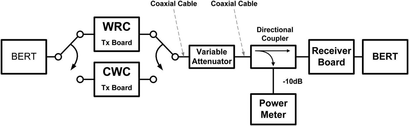
In order to verify the power control abilities, at first, the sensitivity levels were measured for the proposed WRC and conventional CWC. Because the WRC system emits a relatively low maximum spectral power, its transmission performance can be degraded for various channel BWs. Customized FPGA digital boards were fabricated for the BER tests. The board is organized with power supplies for the RF boards, a variable random-digital-data-generator, and a received-bits-comparison-and-count. In order to obtain impartial measurements, the same experimental environments were established such as the same receiver system and communication link. Figure 5 presents the BER test measurement set-up that consists of a transmitter, a variable attenuator, and a receiver that was connected by coaxial cables to eliminate the effect of other interferers. The received power is monitored by a 10 dB directional coupler and a microwave power meter. During the transmitted RF power is adjusted, the bit errors were measured for each received power. The received RF channel power can be expressed in terms of the signal-to-noise ratio (S/N), because the receiver has the same noise BW of the envelope detector. In order to avoid numerically uncontrollable noise and interference, the ideal measurements were performed. The digital PRBS information data have a data-rate of 64 kbps and random pattern of 29−1. In BER measurements, a total of 38 400 000 bits (38.4 Mbits) were tried for each received RF power level from −90 to −50 dBm.
Experimental setup for BER tests.
Figure 6 presents the measured BERs for the CWC and WRC systems. A BER of 10−3 is considered to be a reliable detection threshold based on the IEEE recommendation [23]. The experimental results present sensitivity levels of −67 dBm for the WRC system and −68 dBm for the conventional CWC one, which show that they have the same data transmitting performance. From the measured sensitivity levels, the communication distances, d were computed for line-of-sight (LOS) environments by the Friis transmission formula in (1).
 $$20 \hbox{log}d = P_T \lpar \hbox{dBm}\rpar - P_R \lpar \hbox{dBm}\rpar + 20 \hbox{log}\lpar \lambda /4\pi \rpar.$$
Measured BERs for received powers.
The communication distance is experimented for the peak emission power of the CWC and the channel power of the WRC. As the peak power and WRC BW are increased, the maximum communication distances are evaluated from BER measurements. In Figure 7, while the communication distance is increased from 40 to 126 m as the CWC peak power varies from 2 to 12 dBm, it is changed from 54 to 140 m as the WRC BW increases from 30 to 200 MHz. For the WRC signal, total transmitted power, P T is adjusted by a product of a power spectral density (dBm/Hz) and a BW (Hz). In order to estimate exact channel power, non-rectangular signal shape and a duty-cycle of on-off keying (OOK)-modulated pulses should be considered. From the experimental results, it is estimated that the adjustment of BW makes the increment of transmitted power from 7.6 to 15.9 dBm. Therefore, the WRC system can achieve the linear power control from BW variations. According to the experimental measurements, the proposed WRC was verified to have almost the same data transmission performance as the conventional CWC, in spite of its adjusted channel BWs. Figure 8 shows the photographs of the implemented WRC system and BER measurement setup.
Communication distances for power control schemes by (a) peak power and (b) channel BW.
Photograph of the implemented WRC system and BER test configuration.
IV. CONCLUSION
The short-range RF communication system has been presented with the BW power control mechanism. From the system design and performance evaluations, it was shown that the proposed system can generate a wideband carrier with flexible BWs and center frequencies and transmit digital data with excellent recovery. In addition, it was confirmed that the WRC with the constant peak power spectrum can maintain the spectral regulation in the ISM bands, and reduce the high linearity of a power amplifier. Furthermore, it can be simply designed with a compact system architecture, as well as a low-power configuration. Therefore, the proposed WRC system can be an excellent candidate for low-powered, inexpensive solutions for the FM-UWB system in IEEE 802.15.6 W-BAN applications.
ACKNOWLEDGEMENTS
This work was supported by Soonchunhyang University Research Fund and the Korea Research Foundation (KRF) grant funded by the Korea government (grant no. 2009-0065375).
 Heejong Lee received his B.S. and M.S. degrees in Information and Communication Engineering from Soonchunhyang University, Korea in 2010 and 2012, respectively. He is currently a Research Engineer in U-Tel Co. Ltd., Korea. His current research interests include RF front-end modules, microwave active component designs.
 Seok-Jae Lee received his B.S. and M.S. degrees in Information and Communication Engineering from Soonchunhyang University, Korea in 2010 and 2012, respectively. He is currently a Ph.D Candidate in Soonchunhyang University. His current research interests include the microwave system architectures, passive/active antenna, and microwave component.
Won-Sang Yoon received his Ph.D. degree in 2010 in the department of the computer and radio communications engineering from the Korea University. Since 1999, he has been a Senior RF/microwave System Engineer in Samsung Thales Ltd., Seongnam, Korea. His current research interests include RF/microwave front-end systems, reconfigurable antennas, and microwave components.
Sang-Min Han received his B.S., M.S., and Ph.D. degrees in Radio Sciences and Engineering from Korea University, Seoul, Korea, in 1996, 1998, and 2003, respectively. From 1999 to 2001, he was a Lecturer in the School of Electrical Engineering, Korea University. From 2003 to 2004, he was a Post-Doctoral Researcher in University of California at Los Angeles (UCLA), USA. From January 2005 to August 2007, he was a Senior Research Engineer with the Samsung Advanced Institute of Technology (SAIT), Yongin, Korea, where he was a Project Leader of the RF System Architecture Team. In September 2007, he joined Soonchunhyang University, Korea. He is currently staying at Georgia Institute of Technology (GIT), Atlanta, USA as a Visiting Scholar.
He is currently an Editorial Board Member of the Journal of Electromagnetic Engineering and Science (JEES) and the Journal of the Korean Institute of Information Technology (JKIIT). He has served on the Editorial Board for the Journal of the Korean Academia-Industrial cooperation Society (JKAIS) from 2008 to 2009. He has authored or co-authored over 200 peer reviewed technical papers and conference papers. He has registered or filed over 40 patents in RF/microwave technology. He appears in Marquis' Who's Who in Science and Engineering (2006–2007) and Marquis' Who's Who in Asia (2007). His research interests include low-power RF/microwave system architectures, active integrated antennas, and reconfigurable RF systems and devices.