Introduction
With the increasing importance of precise navigation, the Global Navigation Satellite System (GNSS) plays a crucial role in various applications. Ensuring the accurate detection of GNSS signals is essential particularly in challenging environments where signal’s quality may vary significantly. In this context, circularly polarized antennas are of great advantage due to their ability to mitigate multipath interference and polarization mismatch [Reference Zhong and Zhang1]. Another important feature is multiband reception, which is essential for compensating for ionospheric effects and achieving precise positioning. For GNSS receivers, it is crucial that the antenna provides broad coverage in both impedance and axial ratio (AR) across the frequency range from 1164 MHz to 1610 MHz, corresponding to a bandwidth of at least 32.2%. This frequency range covers the L5 and L1 bands used by the primary navigation satellite systems: GPS (America), Beidou (China), Galileo (Europe), and GLONASS (Russia) [Reference Zhong and Zhang1, Reference Montenbruck, Steigenberger and Hauschild2], ensuring compatibility across these systems and maximizing the number of detected satellites at any given time.
The effectiveness of GNSS applications heavily relies on the number of satellites a receiver can detect simultaneously. A greater number of detected satellites results in improved positioning accuracy. This is why, along with circular polarization and multiband features, the antenna should be designed to maximize its beamwidth in order to have a wide angular coverage for satellite detection.
As part of the 23rd French National Microwave Days (JNM) at Antibes-Juan les Pins in 2024, a student competition was organized to identify the most effective receiving antenna for GNSS signals. The challenge required designing antennas to receive GNSS L1 and L5 signals with right-hand circular polarization (RHCP) within a maximum size of  $100 \times 100 \times 50$ mm3. Various antennas were evaluated in head-to-head matches, and the qualification was based on the number of satellites detected during the first 30 s of receiver operation.
Our winning antenna is presented in this paper. The antenna consists of a single-fed crossed-dipole strip antenna relying on parasitic elements and a closed cavity to achieve wide bandwidth coverage.
Several previous works have been reviewed to gain insight into key factors that ensure optimal performance. In [Reference Thaysen, Jakobsen and Appel-Hansen3], a cavity-backed logarithmic antenna was presented for wideband applications as frequency independent radiating structure. In [Reference Zhong and Zhang1], a spiral traveling wave-fed slot antenna with a cavity was proposed, which proved effective in improving the AR bandwidth. Other works have focused on the design of crossed dipole antennas with a reflector plane to enhance gain and the use of parasitic elements to broaden the bandwidth [Reference Wang, Fang, En, Huang, Shao and Yao4–Reference Baik, Lee, Yoon, Lee and Kim7]. An exhaustive overview, supported by a series of simulations, led to the design of a crossed dipole antenna backed by a closed cavity to further enhance the AR bandwidth, with rectangular and spiral structures as inner and outer parasitic elements, respectively.
This paper is organized as follows. Section 2 provides a detailed description of the antenna design, highlighting key stages in the design process. Section 3 presents the simulation and measurement results, comparing the antenna performance observed in both cases. Section 4 reports the contest results. Finally, Section 5 draws the conclusion.
Antenna design and parameters
The copper antenna has been manufactured on a 1.6 mm thick Rogers 4003C substrate, with a relative permittivity and a loss tangent of 3.38 and 0.0027, respectively, at 10 GHz. To enhance the performance of the structure, the radiating elements have been backed by a cuboid copper cavity with a height of approximately 45.7 mm and a  $35\,\mu$m thick copper walls. The antenna uses a single-feed configuration, where a semi-rigid 50Ω coaxial cable passes through the cavity. The design of the proposed antenna is shown in Figure 1, with the values of the structure parameters listed in Table 1.
The geometrical design was primarily based on the work presented in [Reference Wang, Fang, En, Huang, Shao and Yao4], which featured a single-feed crossed dipole antenna, with quarter wavelength rounded microstrip lines serving as phase shifters between the arms of the crossed dipoles. To achieve enhanced bandwidth, the design included eight rectangular-shaped parasitic elements in total: four inner parasitic elements and four outer parasitic elements (the placement of the inner and outer structures is clarified in Figure 1a). Additionally, a reflector plane was incorporated beneath the PCB, with an offset of about a quarter-wavelength of the center frequency, to create a unidirectional radiation pattern and achieve a broad bandwidth for circular polarization.
Antenna simulated designs and parameters: (a) Antenna top and bottom layer (in yellow and blue respectively) of the front pannel and (b) Antenna lateral view of the front pannel design backed by the cavity structure.

In contrast to the reference design, lateral reflectors have been added to form a fully enclosed cavity and further optimize the AR performance of the antenna. Moreover, while the reference design featured a rectangular shape for both inner and outer parasitic elements, our design retains the rectangular shape for the inner parasitic elements while introducing a spiral shape for the outer ones. This geometric adjustment effectively utilizes the remaining space after incorporating the inner parasitic elements, enhancing performance while fitting within the specified maximum dimensions of  $100 \times 100 \times 50$ mm3.
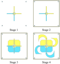
In order to highlight the impact of the closed cavity and the parasitic elements on the performances of the antenna, Figure 2 shows four key stages of the antenna’s development. Stage 1 represents the initial crossed dipole design with only the reflector plane; Stage 2 corresponds to the addition of lateral reflectors to form a closed cavity; in Stage 3, the rectangular inner parasitic elements are added; and finally, Stage 4 marks the completion of the design by the addition of the spiral outer parasitic elements.
Four different stages of the antenna’s development.

Dimensions of the antenna design

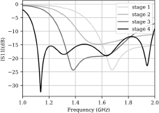
The evolution of the antenna’s reflection coefficient and AR following the different stages of the antenna are shown in Figures 3 and 4, respectively. It is worth noting that the AR observed in this section is not the AR of the main direction of radiation ( $\theta = 0^{\circ}$) but rather the maximum value of the AR detected in the aperture angle of 160∘ (between
 $\theta=-80^{\circ}$ and
 $\theta=80^{\circ}$) across the relevant frequency range shown in the graph. This broader view is essential because it has been noted that satellite detection can occur at elevations as low as 10∘, making it crucial to keep an acceptable AR across the entire coverage angle.
It can be seen that at Stage 1, the antenna exhibited narrowband behavior in terms of the reflection coefficient, while the AR exceeded 15 dB across the entire band of interest for both the  $\phi = 0^{\circ}$ and
 $\phi = 90^{\circ}$ planes, indicating that circular polarization was poorly achieved. The formation of the closed cavity in Stage 2 notably improved the AR, particularly at higher frequencies, while slightly broadening the reflection coefficient bandwidth and shifting it toward the desired frequency range. The addition of the inner parasitic elements in Stage 3 further improved both the impedance bandwidth (IBW) (S11) and AR. In Stage 4, the introduction of the spiral outer parasitic elements enlarged the antenna, leading to an extended −10 dB IBW of
 $58.54\%$, particularly improving impedance matching at lower frequencies. Additionally, the antenna achieved a maximum AR lower than 6 dB between 1.2 GHz and 1.6 GHz.
The currents on the simulated structure have been plotted in Figure 5 for a phase of 0∘, 45∘, and 90∘. The direction of the surface current vectors for a 0∘ and 90∘ phasing is orthogonal to each other, pointing to a circular polarization. The evolution of the direction of the surface current vector through the three different phases shows that the current flow runs in anti-clockwise direction to produce an RHCP.
Simulated reflection coefficient of the antenna for different stages.

Simulated axial ratio at several stages of development: (a) Maximum axial Ratio for an aperture  $\theta \in [-80^{\circ}, 80^{\circ}]$ versus frequency for
 $\phi = 90^{\circ}$ and (b) Maximum axial Ratio for an aperture
 $\theta \in [-80^{\circ}, 80^{\circ}]$ versus frequency for
 $\phi = 0^{\circ}$.

Surface current at 1.4 GHz.

Simulation and measurement
Figure 6 shows photographs of the final fabricated prototype. To assess the actual figures of merit of the antenna and validate the simulation results, the antenna was tested and characterized in the anechoic chamber to evaluate its radiation pattern characteristics as well as its impedance matching.
Crossed dipole antenna prototype.

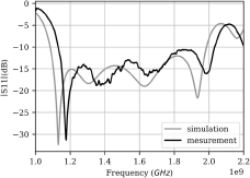
Figure 7 shows a comparison between the measured and simulated reflection coefficients, revealing good agreement between the two. The simulation predicts a −10 dB IBW of  $58.54\%$, centered at 1.535 GHz and ranging from 1.086 GHz to 1.985 GHz, comfortably exceeding the required bandwidth. The measurement results are slightly shifted with respect to the simulation but still cover the band of interest with a −10 dB IBW of
 $56.97\%$ centered at 1.58 GHz and ranging from 1.131 GHz to 2.032 GHz.
Simulated and measured reflection coefficient of the antenna.

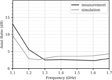
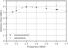
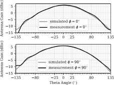
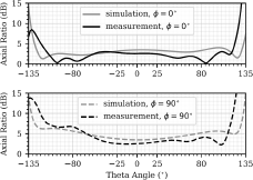
Figure 8 shows the comparison between the simulated and measured AR values in the main direction of radiation ( $\theta= 0^{\circ}$) across some relevant frequencies. The measurement was performed over a more focused range, from 1.1 GHz to 1.7 GHz, as the primary interest lies in the 1.164–1.61 GHz band. Good agreement is observed between the results, with the measured AR ranging from 7 dB to 2.8 dB over the frequency range of 1.164–1.3 GHz covering the L5 band (1.164–1.189 GHz), and maintaining a value lower than 2.7 dB across the L1 band (1.559–1.610 GHz). Additionally, the simulated and measured gain of the antenna are compared in Figure 9 across the same frequency band. The measured gain is also in line with the stimulated one, and a maximum gain of 6 dBic can be spotted at 1.3 GHz. Finally, Figures 10 and 11 show a comparison between measurements and simulations for gain and AR, respectively, following the variation of θ at the frequency of 1.4 GHz, and a good agreement is also observed. These results confirm that the proposed antenna design successfully meets the bandwidth and polarization requirements for GNSS applications, covering the necessary L1 and L5 bands with appropriate circular polarization characteristics.
Simulated and measured axial ratio of the antenna for several frequencies in the direction of radiation of the antenna ( $\theta=0^{\circ}$).

Simulated and measured gain of the antenna for several frequencies.

Simulated and measured gain of the antenna at 1.4 GHz.

Simulated and measured axial ratio of the antenna at 1.4 GHz.

Contest results
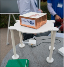
The designed antenna was tested, among others, at the 3rd design competition of the the 23rd French National Microwave Days (JNM) at Antibes Juan-les-pins (4–7 June 2024). The antenna test was conducted using a Quectel LC29HAAMD GNSS receiver and the QGNSS software, which decoded NMEA frames from the GNSS module. A full cold start was initiated, lasting for 30 s. At the end of this period, the panel evaluated how many GNSS satellites were detected. The tested antennas were placed as far away possible from external environment objects and were mounted on a PLA (Polylactic Acid) dielectric support and fed through a centered hole to allow the SMA connector to pass through. The connector was attached to a flexible SMA (SubMiniature version A) cable, which ran vertically along the dielectric support for 30 cm down to the GNSS receiver. The competition consisted of “Battles”: matches were held where two antennas were tested simultaneously against each other using two identical test benches.
Antenna under test during the competition of the French National Microwave Days.

The number of satellites detected by each antenna was used as a benchmark to compare the antennas. The designed antenna, along with another competitor, was awarded first place in ex-aequo by detecting a total of 46 satellites within the 30 s period. Figure 12 shows the antenna under test at the final stage of the competition.
Conclusion
In this paper, a wide band circularly polarized antenna for GNSS applications was designed, optimized, and tested. The antenna, based on two crossed dipoles in phase quadrature with a single feed configuration, successfully covers the GPS L1 and L5 bands. The performances of the antenna were enhanced by incorporating rectangular and spiral shaped parasitic elements and by backing the design with a closed cavity, resulting in a −10 dB IBW of  $56.97\%$, and an AR lower than 2.7 dB across a significant portion of the band of interest. Both simulated and measured results show good agreement, confirming the antenna’s suitability for practical application. Its performances were validated during the French National Microwave Days (JNM) student competition, where it demonstrated high satellite detection capability within the competition’s 30 s evaluation window. The proposed antenna meets the demands of GNSS systems, providing an efficient solution for applications requiring reliable multiband reception and circular polarization to ensure optimal satellite tracking.
Acknowledgements
The authors would like to express their gratitude to M. Nicolas Corrao for his promptness in realizing the designed antenna. They also extend their acknowledgment to M. Guillaume Ferré, M. Fabien Ferrero, M. Anthony Ghiotto, the MTT and AP France chapters, and the organizers of the JNM for their support.
This research received no specific grant from any funding agency, commercial or not-for-profit sectors.
Competing interests
The authors declare none.

Rim Berro received her Engineering Diploma in 2023 from Brest National School of Engineering (ENIB). She is currently a Ph.D. student at the University of Grenoble Alpes.

Luca Persano received his Engineering Diploma in 2022 from the Grenoble National Polytechnical Institute (INP). He is currently a Ph.D. candidate at the University of Grenoble Alpes.

Marwan Jadid was born in Beirut, Lebanon, in 1993. He pursued a Ph.D. in radio frequency at the French Alternative Energies and Atomic Energy Commission (CEA), in collaboration with the French Space Agency (CNES), Toulouse, France, and the doctoral school of electronics engineering (EEATS), Grenoble Alps University (UGA), Grenoble, France. His research interests include electrically small antennas, antennas with circular polarization, antenna pattern synthesis, antenna arrays, reactively loaded antennas, parasitic antenna arrays, and frequency reconfigurable antennas. His project contributions comprise antenna technology development for IoT and industrial applications, UHF RFID systems, anti-jamming systems, space applications for terrestrial reception, and spectrum surveillance for CubeSats.

Nhu-Huan Nguyen was born in Hanoi, Vietnam, in 1993. He received the Control and Automation Engineer degree from Hanoi University of Science and Technology, Vietnam, in 2016, the M.Sc. degree in Electronics, Energy and Automatics from University of Grenoble-Alpes, France, in 2017, and the double Ph.D. degree from the University of Grenoble Alpes and the Ecole Polytechnique Montréal in optics and radiofrequency in 2021. He was a post-doctoral fellow at the CROMA laboratory (Grenoble) from 2021 to 2022. Since 2022, he is an associate professor at the engineering school PHELMA – Grenoble INP and the CROMA laboratory. His research interests are focused on sustainable electronics and millimeter wave circuits and systems.

Christophe Delaveaud completed a Ph.D. in Optical Communication and Microwave Techniques in 1996 at the University of Limoges. After industrial experience at Radiall (Voreppe, France), he joined the Electronic and Information Technology Laboratory of the French Atomic Energy and Alternatives Energy Commission (CEA-Leti) in 2002. Since 2010, he has been the Head of the Antennas and Propagation Laboratory at CEA-Leti and was appointed Research Director of CEA in 2019. His research interests include electromagnetism applied to antennas (miniature antennas, multiantenna systems, reconfigurable antennas) and propagation, as well as microwave circuits for RF transmitters. Dr. Delaveaud received his Accreditation to Direct Physics Research at the University Joseph Fourier, Grenoble, in 2010. He has contributed to over 280 articles and holds 24 patents. He serves as a reviewer for numerous journals and conferences in microwaves, antennas, and propagation.

Tan-Phu Vuong received his Ph.D. in electrical engineering from the Institut National Polytechnique (INP), Toulouse, France, in 1999. From September 2001 to September 2008, he was an Associate Professor in microwave and wireless systems at ESISAR. Since September 2008, he has been a Professor at PHELMA, Grenoble INP-UGA, France. Dr. Vuong has supervised 36 Ph.D. theses and published 65 papers in international journals, with over 200 communications at international conferences. He is a member of several review committees and scientific societies and has managed ten research projects. He was the Vice President of the IEEE French Section from 2010 to 2013. He has been the secretary of the MTT IEEE France Chapter since 2016 and co-director of the Grenoble University Space Center (CSUG) since July 2024. His research interests include modeling passive RF and millimeter-wave components, air-filled SIW, metamaterials, and designing small and printed antennas for mobile, RFID, and UWB systems.

Pascal Xavier is a Full Professor at Grenoble Alpes University, primarily involved in teaching electronics and physics. He heads the DHREAMS (Devices in High Frequencies for Sustainable Electronics and Complex Systems) research team within the CROMA laboratory, focusing on RF devices and micro-sensors with low environmental impact or for environmental applications. He has supervised 15 Ph.D. theses, filed 4 patents, and authored 35 journal articles and 94 conference papers. He currently serves as associate editor of the IEEE Transactions on Components, Packaging and Manufacturing Technology, and is the coordinator of the European “DESIRE4EU” project (EIC “Responsible Electronics” challenge). He is also a flexible electronics expert for the European “ICOS” project (Horizon), manager of the CNRS “CIRCABIO” MITI contract, and CNRS project leader for the creation of the DEFIE GdR (“Dispositifs Electroniques à Faibles Impacts Environnementaux”).